BMW I3 2015 I01 Owner's Manual
Manufacturer: BMW, Model Year: 2015, Model line: I3, Model: BMW I3 2015 I01Pages: 236, PDF Size: 17.6 MB
Page 171 of 236
Switch off any functions that
are not currently needed
Functions such as the rear window defroster
require a lot of energy and reduce the range,
especially in city and stop-and-go traffic.
Reel off these functions if they are not needed.
The ECO PRO and ECO PRO+ driving pro‐
grams support the energy-conserving use of
comfort features. They automatically perform a
partial or complete deactivation of these func‐
tions.
Have maintenance carried
out
Have vehicles maintained regularly to achieve
optimal vehicle efficiency and operating life.
The maintenance should be carried out by
your service center.
Also note the BMW Maintenance System, refer
to page 188.
ECO PRO and ECO PRO+ The concept
ECO PRO and ECO PRO+ support an efficient
driving style. To this end, the control of the
drive is optimized for moderate acceleration,
and adapted to lighting and comfort features,
such as climate control output. Some vehicle
functions cannot be used during activated
drive mode ECO PRO and ECO PRO+.
In addition, context-sensitive instructions can
be displayed that assist in driving efficiently.
At a glance With ECO PRO and ECO PRO+ different set‐
tings are made in the respective mode.ECO PRO▷Reduce heat output or heating cycle for ex‐
terior mirror, rear window and seat heating.▷What reduces the the cooling and heating
output of the climate control system.▷The speed is limited to an adjustable maxi‐
mum value between 50 mph/80 km/h and
80 mph/130 km/h. To intentionally exceed
the speed limit, press the accelerator pedal
all the way down.
ECO PRO+
The cooling and heating output of the climate
control system are additionally deactivated on
ECO PRO+ activation.
The low beams are dimmed.
The maximum speed is limited to
55 mph/90 km/h. In special situations, the
speed limit can be consciously exceeded by applying the accelerator pedal.
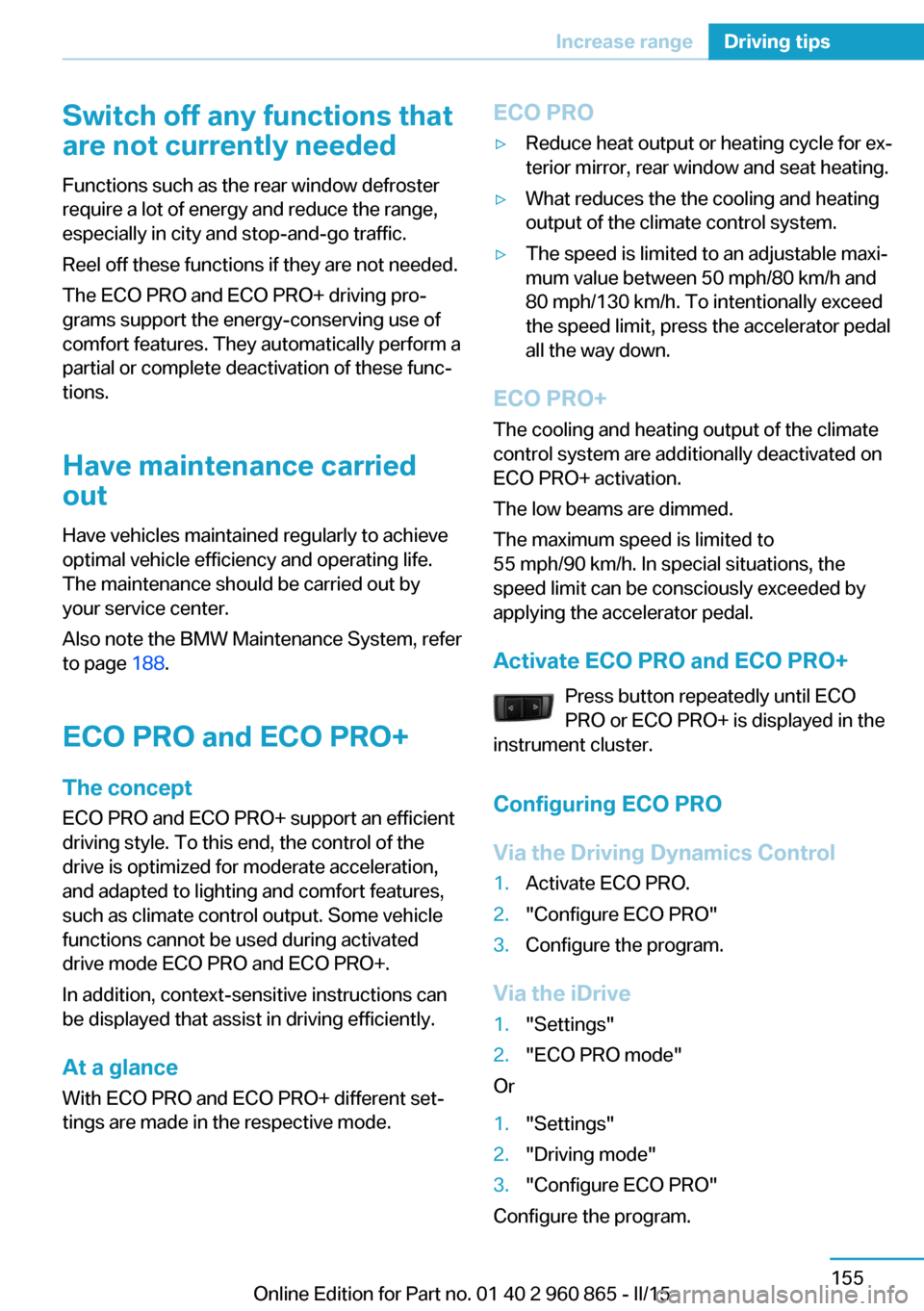
Activate ECO PRO and ECO PRO+ Press button repeatedly until ECO
PRO or ECO PRO+ is displayed in the
instrument cluster.
Configuring ECO PRO
Via the Driving Dynamics Control
1.Activate ECO PRO.2."Configure ECO PRO"3.Configure the program.
Via the iDrive
1."Settings"2."ECO PRO mode"
Or
1."Settings"2."Driving mode"3."Configure ECO PRO"
Configure the program.
Seite 155Increase rangeDriving tips155
Online Edition for Part no. 01 40 2 960 865 - II/15
Page 172 of 236
ECO PRO Tip▷"Limit at:":
Adjust the ECO PRO speed.▷"ECO PRO speed warning":
The output is reduced once the set ECO
PRO speed is reached.
Coasting
With little pressure on the accelerator pedal,
the vehicle can coast without energy recovery.
The accelerator pedal indicator in the instru‐
ment display is centered between CHARGE
and ePOWER during coasting.
ECO PRO climate control "ECO PRO climate control"
Climate control is set to be fuel-efficient.
By making a slight change to the set tempera‐
ture, or slowly adjusting the rate of heating or
cooling of the car's interior, fuel consumption
can be economized.
ECO PRO potential Shows potential savings with the current set‐
tings in percentages.
Display in the instrument cluster
Efficiency display
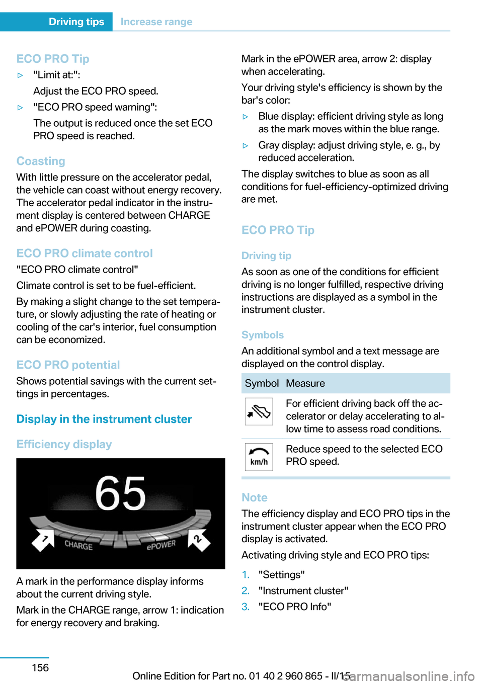
A mark in the performance display informs
about the current driving style.
Mark in the CHARGE range, arrow 1: indication
for energy recovery and braking.
Mark in the ePOWER area, arrow 2: display
when accelerating.
Your driving style's efficiency is shown by the
bar's color:▷Blue display: efficient driving style as long
as the mark moves within the blue range.▷Gray display: adjust driving style, e. g., by
reduced acceleration.
The display switches to blue as soon as all
conditions for fuel-efficiency-optimized driving
are met.
ECO PRO Tip Driving tip
As soon as one of the conditions for efficient
driving is no longer fulfilled, respective driving
instructions are displayed as a symbol in the
instrument cluster.
Symbols
An additional symbol and a text message are
displayed on the control display.
SymbolMeasureFor efficient driving back off the ac‐
celerator or delay accelerating to al‐
low time to assess road conditions.Reduce speed to the selected ECO
PRO speed.
Note
The efficiency display and ECO PRO tips in the
instrument cluster appear when the ECO PRO
display is activated.
Activating driving style and ECO PRO tips:
1."Settings"2."Instrument cluster"3."ECO PRO Info"Seite 156Driving tipsIncrease range156
Online Edition for Part no. 01 40 2 960 865 - II/15
Page 173 of 236
Indications on the Control DisplayeDRIVE
Information on fuel consumption and technol‐
ogy can be displayed while driving.1."Vehicle info"2."eDRIVE"
Displaying ECO PRO Tips
ECO PRO Tips can be displayed while driving
as a note in the split screen in the energy flow
display.
Displaying ECO PRO Tips:
1."Vehicle info"2."eDRIVE"3. "ECO PRO Tips"
Settings are stored for the profile currently in
use.
ECO PRO driving style analysis
The concept
The system helps develop a particularly effi‐
cient driving style and to save energy.
For this purpose, the driving style is analyzed.
The assessment is done in various categories
and is displayed on the Control Display.
Those assessments will help you adjust your
driving style and save some energy.
The last fifteen minutes of a trip are evaluated.
The range of the vehicle can be extended by
an efficient driving style.
Functional requirement The function is only available in ECO PRO
mode.
Calling up ECO PRO driving styleanalysis
1.Activate ECO PRO.2."eDRIVE"3. Select the symbol.
Display on the Control Display
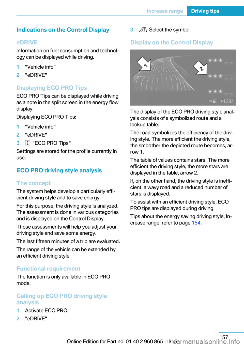
The display of the ECO PRO driving style anal‐
ysis consists of a symbolized route and a
lookup table.
The road symbolizes the efficiency of the driv‐
ing style. The more efficient the driving style,
the smoother the depicted route becomes, ar‐
row 1.
The table of values contains stars. The more
efficient the driving style, the more stars are
displayed in the table, arrow 2.
If, on the other hand, the driving style is ineffi‐
cient, a wavy road and a reduced number of
stars is displayed.
To assist with an efficient driving style, ECO
PRO tips are displayed during driving.
Tips about the energy saving driving style, In‐
crease range, refer to page 154.
Seite 157Increase rangeDriving tips157
Online Edition for Part no. 01 40 2 960 865 - II/15
Page 174 of 236
Online Edition for Part no. 01 40 2 960 865 - II/15
Page 175 of 236
Mobility
In order to always ensure your mobility, you will find important information on operating fluids,wheels and tires, maintenance and Roadside Assistance in the following.Online Edition for Part no. 01 40 2 960 865 - II/15
Page 176 of 236
Charging vehicleVehicle features and options
This chapter describes all standard, country-
specific and optional features offered with the
series. It also describes features that are not
necessarily available in your car, e. g., due to
the selected options or country versions. This
also applies to safety-related functions and
systems. The respectively applicable country
provisions must be observed when using the
respective features and systems.
The concept
The vehicle can be charged using various
charging cables at charging stations or hous‐
hold sockets. Control and monitoring of the
charging process are handled completely au‐
tomatically. The charge current strength can
be set by means of the Control Display.
General information High-voltage batteryThe high-voltage battery is used as an energy
accumulator. The high-voltage battery can be
charged by energy recovery during the trip or
via the power grid.
When charging via the power grid, you can
chose between the following variants.▷Level 1 charging via a household socket.▷Level 2 charging via a Level 2 charging sta‐
tion.▷Charging via a DC charging station.
Level 1 charging is possible via a household
socket within a voltage range of 100 volts to
240 volts.
For optimal use of the energy from the power
grid, charging at a Level 2 charging station,
such as BMW i Wallbox, is recommended.
Charge current
The charge current strength is indicated in am‐
peres.
The vehicle cannot automatically detect the
maximum permissible charge current strength
of the power grid during charging via a house‐
hold socket or charging station.
Level 1 charging Prior to the first Level 1 charging at your own
household socket, as well as when charging at external electrical power sockets in Level 1,
the allowed charge current strength must be
determined, e.g. by a qualified electrician.
The charge current strength for Level 1 charg‐
ing, refer to page 165, can be adjusted in the
vehicle in three steps.
At delivery, the charge current for
Level 1 charging is set to "Low".
Depending on the country-specific version,
one of four ampere ratings is printed on the
Level 1 charging cable. This ampere rating is
the limit which must be adhered to for the vehi‐
cle if the charge current is set to "Maximum".
According to the market-specific version, the
charge current strength changes differently if
the setting "Reduced" or "Low" is selected."Maximum""Reduced""Low"8 A6 A6 A10 A7.5 A6 A12 A9 A6 A15 A11.25 A7.5 A
Charging at a Level 2 charging station
The permitted charge current strength must
be determined prior to charging at a
Level 2 charging station, e.g. from the operator
Seite 160MobilityCharging vehicle160
Online Edition for Part no. 01 40 2 960 865 - II/15
Page 177 of 236
of the Level 2 charging station. The permitted
charge current strength can vary by country.
The charge current strength for Level 2 charg‐
ing, refer to page 166, can be adjusted in the
vehicle in two steps.
At delivery, the charge current for
Level 2 charging is set to "Reduced". This set‐
ting should be maintained, unless it was veri‐
fied that a higher charge current strength is
permitted in the individual case.
The charge current changes depending on the
setting."Maximum""Reduced"32 A20 A
Depending on the charge current, the charging
duration changes.
Range Extender
With Range Extender, refer to page 69,
switched on, the current charging state can be
maintained. In this way, a higher range is ach‐
ieved.
Hints Working with electrical current
When working with electrical current, ob‐
serve the safety regulations. Otherwise, with
high voltage or excess current there is a risk to
persons and property, e.g., from electrocution or fire.◀
Have the charging device checked be‐
fore commissioning
Before the initial charging process, have your
own charging device checked at the charging location by a qualified electrician, that is,
charging port on the vehicle, charging cable,
charging station or household socket and con‐
nected circuits. Otherwise, there is a danger of
damage to the vehicle and overloading of the
supply mains at the charging location.◀
Follow instructions at the charging sta‐
tion
When working with electrical current, follow
the instructions at the charging station. Other‐
wise, there is a risk of an accident.◀
Make sure that the charging device is in
flawless operating condition
Only use the charging device in a flawless con‐
dition. Otherwise, a risk of fire may result, e.g.,
from the device heating up because of, say,
worn contacts or damage.◀
No simultaneous charging and refueling
Do not refuel while a charging cable is
plugged in, and maintain an adequate safety
distance from highly flammable materials. Oth‐
erwise, there is a danger of personal injury and
property damage from burning fuel vapors,
e.g., if the charging cable is improperly plug‐
ged in or unplugged.◀
Have the charging port cleaned by
trained personnel
If the charging port is dirty, have the car
cleaned only by appropriately trained person‐
nel. Otherwise, there is a danger of injury from high voltage.◀
Charging cable General information
Use a Level 1 charging cable, Level 2 charging
cable or the permanently installed charging ca‐
ble of a charging station to charge the vehicle.
Different charging cables can be required de‐ pending on the country.
Hints Use approved charging cables only
Use only approved charging cables or
charging stations for charging. Otherwise,
there is a danger of property damage or per‐Seite 161Charging vehicleMobility161
Online Edition for Part no. 01 40 2 960 865 - II/15
Page 178 of 236
sonal injury, e.g., from burning cables. Informa‐
tion about the approved charging cables can
be obtained from the service center.◀
Use the charging cable only for charging
the vehicle, and do not extend it
Use the charging cable only for charging the
vehicle and do not extend it with cables or
adapters. Otherwise, it may not be possible to
complete the charging process or property
damage might occur, e.g., due to a cable fire.◀
Do not use any damaged charging cables
Do not use any damaged charging ca‐
bles. Otherwise, there is a risk of injury from
high voltage.◀
Level 1 charging cable With the Level 1 charging cable, it is permissi‐
ble to perform charging from grounded house‐
hold sockets. At the power connection of a
household socket, charging is done with alter‐
nating current.
When a Level 1 charging cable is used, this
may produce efficiency values other than indi‐
cated on the energy label.
Level 2 charging cable
The Level 2 charging cable makes it possible
to recharge at sockets of designated
Level 2 charging stations using a special plug.
Charging is performed with alternating current
at designated Level 2 charging stations. The
charging process can be completed faster than
at household sockets.
If necessary, the charging cable is attached to
the charging station.
If a Level 2 charging cable is used, apply the
corresponding setting on the Control Display,
refer to page 166.
DC charging cable The DC charging cable that is permanently in‐
stalled at the charging station makes is possi‐ble to charge at DC charging stations. Charg‐
ing is performed with direct current at
designated DC charging stations. At the higher
lidacity current connection of a DC charger
station the charging time is significantly lower
than with a household socket or a level 2
charging station.
During charging at a DC charging station, an
indication in the instrument cluster, refer to
page 166, is displayed.
Storage
The Level 1 charging cable is located in the ca‐
ble compartment under the hood.
The Level 2 charging cable can be stored in
the same place.
Moisture can penetrate into the occasional use
cable compartment, e.g. in a car wash.
If required, store the charging cable with the
installed plug cover to prevent moisture in the
charging cable plug.Seite 162MobilityCharging vehicle162
Online Edition for Part no. 01 40 2 960 865 - II/15
Page 179 of 236
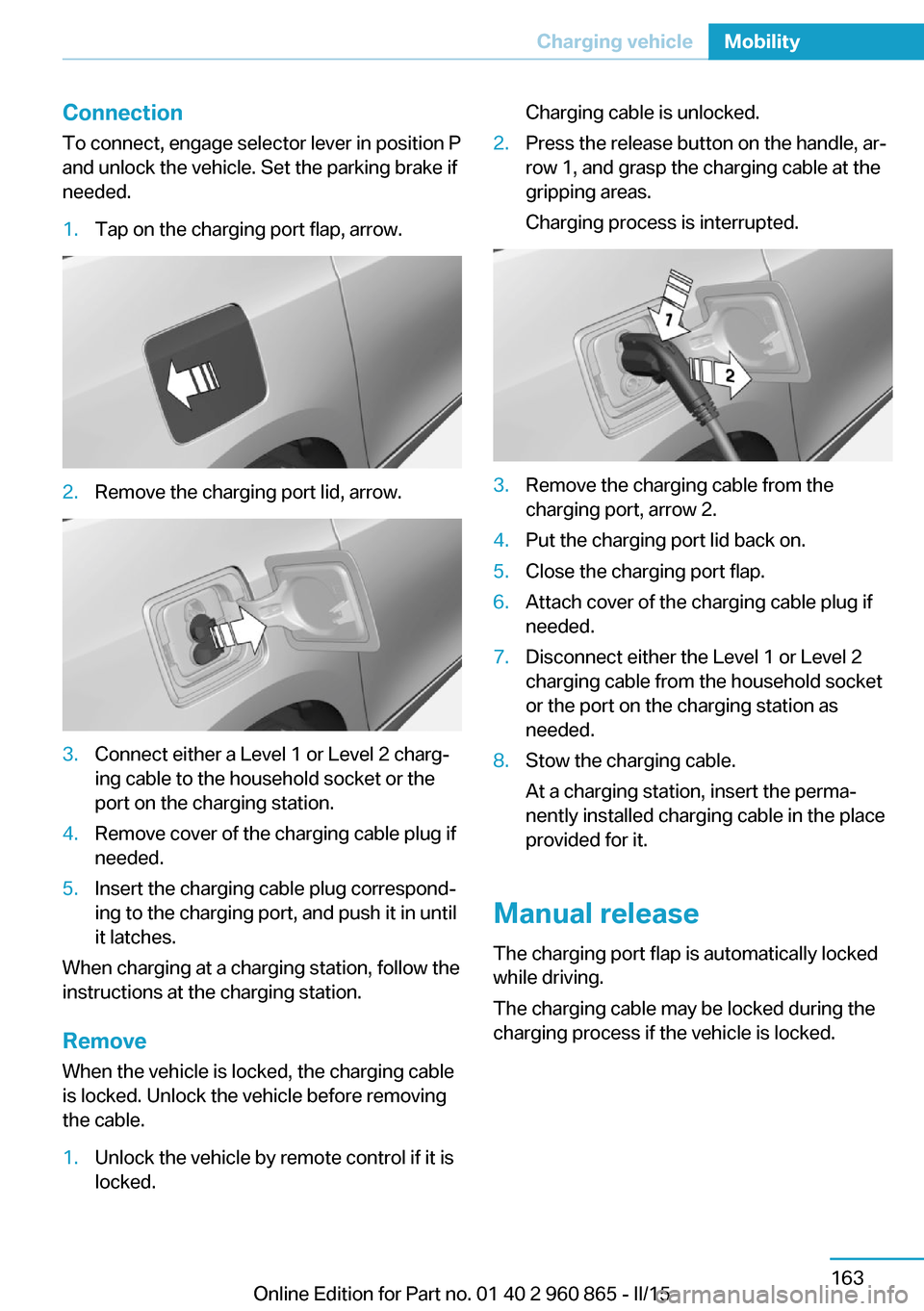
ConnectionTo connect, engage selector lever in position P
and unlock the vehicle. Set the parking brake if
needed.1.Tap on the charging port flap, arrow.2.Remove the charging port lid, arrow.3.Connect either a Level 1 or Level 2 charg‐
ing cable to the household socket or the
port on the charging station.4.Remove cover of the charging cable plug if
needed.5.Insert the charging cable plug correspond‐
ing to the charging port, and push it in until
it latches.
When charging at a charging station, follow the
instructions at the charging station.
Remove
When the vehicle is locked, the charging cable
is locked. Unlock the vehicle before removing
the cable.
1.Unlock the vehicle by remote control if it is
locked.Charging cable is unlocked.2.Press the release button on the handle, ar‐
row 1, and grasp the charging cable at the
gripping areas.
Charging process is interrupted.3.Remove the charging cable from the
charging port, arrow 2.4.Put the charging port lid back on.5.Close the charging port flap.6.Attach cover of the charging cable plug if
needed.7.Disconnect either the Level 1 or Level 2
charging cable from the household socket
or the port on the charging station as
needed.8.Stow the charging cable.
At a charging station, insert the perma‐
nently installed charging cable in the place
provided for it.
Manual release
The charging port flap is automatically locked
while driving.
The charging cable may be locked during the
charging process if the vehicle is locked.
Seite 163Charging vehicleMobility163
Online Edition for Part no. 01 40 2 960 865 - II/15
Page 180 of 236
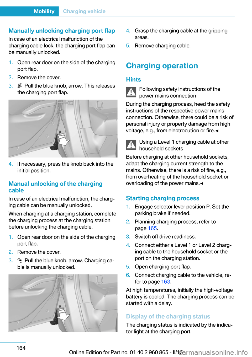
Manually unlocking charging port flapIn case of an electrical malfunction of the
charging cable lock, the charging port flap can
be manually unlocked.1.Open rear door on the side of the charging
port flap.2.Remove the cover.3. Pull the blue knob, arrow. This releases
the charging port flap.4.If necessary, press the knob back into the
initial position.
Manual unlocking of the charging
cable
In case of an electrical malfunction, the charg‐
ing cable can be manually unlocked.
When charging at a charging station, complete
the charging process at the charging station
before unlocking the charging cable.
1.Open rear door on the side of the charging
port flap.2.Remove the cover.3. Pull the blue knob, arrow. Charging ca‐
ble is manually unlocked.4.Grasp the charging cable at the gripping
areas.5.Remove charging cable.
Charging operation
Hints Following safety instructions of the
power mains connection
During the charging process, heed the safety
instructions of the respective power mains
connection. Otherwise, there could be a risk of
personal injury or property damage from high
voltage, e.g., from electrocution or fire.◀
Using a Level 1 charging cable at other
household sockets
Before charging at other household sockets,
adapt the charging current strength to the
mains. Otherwise, there is a risk of fire, e.g.,
from overheating of the household socket or
overloading of the power mains.◀
Starting charging process
1.Engage selector lever position P. Set the
parking brake if needed.2.Planning charging process, refer to
page 165.3.Switch off drive readiness.4.Connect either a Level 1 or Level 2 charg‐
ing cable to the household socket or the
port on the charging station.5.Open charging port flap.6.Connect charging cable to the vehicle, re‐
fer to page 163.
At high temperatures, initially the high-voltage
battery is cooled. The charging process can be
started with a delay.
Display of the charging status
The charging status is indicated by the indica‐
tor light at the charging port.
Seite 164MobilityCharging vehicle164
Online Edition for Part no. 01 40 2 960 865 - II/15