ESP BMW I3 2015 I01 Repair Manual
[x] Cancel search | Manufacturer: BMW, Model Year: 2015, Model line: I3, Model: BMW I3 2015 I01Pages: 236, PDF Size: 17.6 MB
Page 176 of 236
Charging vehicleVehicle features and options
This chapter describes all standard, country-
specific and optional features offered with the
series. It also describes features that are not
necessarily available in your car, e. g., due to
the selected options or country versions. This
also applies to safety-related functions and
systems. The respectively applicable country
provisions must be observed when using the
respective features and systems.
The concept
The vehicle can be charged using various
charging cables at charging stations or hous‐
hold sockets. Control and monitoring of the
charging process are handled completely au‐
tomatically. The charge current strength can
be set by means of the Control Display.
General information High-voltage batteryThe high-voltage battery is used as an energy
accumulator. The high-voltage battery can be
charged by energy recovery during the trip or
via the power grid.
When charging via the power grid, you can
chose between the following variants.▷Level 1 charging via a household socket.▷Level 2 charging via a Level 2 charging sta‐
tion.▷Charging via a DC charging station.
Level 1 charging is possible via a household
socket within a voltage range of 100 volts to
240 volts.
For optimal use of the energy from the power
grid, charging at a Level 2 charging station,
such as BMW i Wallbox, is recommended.
Charge current
The charge current strength is indicated in am‐
peres.
The vehicle cannot automatically detect the
maximum permissible charge current strength
of the power grid during charging via a house‐
hold socket or charging station.
Level 1 charging Prior to the first Level 1 charging at your own
household socket, as well as when charging at external electrical power sockets in Level 1,
the allowed charge current strength must be
determined, e.g. by a qualified electrician.
The charge current strength for Level 1 charg‐
ing, refer to page 165, can be adjusted in the
vehicle in three steps.
At delivery, the charge current for
Level 1 charging is set to "Low".
Depending on the country-specific version,
one of four ampere ratings is printed on the
Level 1 charging cable. This ampere rating is
the limit which must be adhered to for the vehi‐
cle if the charge current is set to "Maximum".
According to the market-specific version, the
charge current strength changes differently if
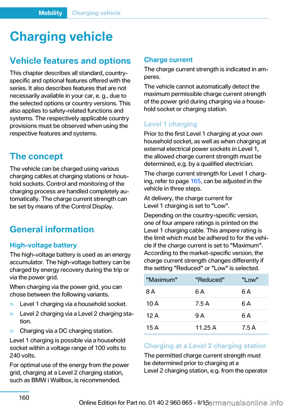
the setting "Reduced" or "Low" is selected."Maximum""Reduced""Low"8 A6 A6 A10 A7.5 A6 A12 A9 A6 A15 A11.25 A7.5 A
Charging at a Level 2 charging station
The permitted charge current strength must
be determined prior to charging at a
Level 2 charging station, e.g. from the operator
Seite 160MobilityCharging vehicle160
Online Edition for Part no. 01 40 2 960 865 - II/15
Page 178 of 236
sonal injury, e.g., from burning cables. Informa‐
tion about the approved charging cables can
be obtained from the service center.◀
Use the charging cable only for charging
the vehicle, and do not extend it
Use the charging cable only for charging the
vehicle and do not extend it with cables or
adapters. Otherwise, it may not be possible to
complete the charging process or property
damage might occur, e.g., due to a cable fire.◀
Do not use any damaged charging cables
Do not use any damaged charging ca‐
bles. Otherwise, there is a risk of injury from
high voltage.◀
Level 1 charging cable With the Level 1 charging cable, it is permissi‐
ble to perform charging from grounded house‐
hold sockets. At the power connection of a
household socket, charging is done with alter‐
nating current.
When a Level 1 charging cable is used, this
may produce efficiency values other than indi‐
cated on the energy label.
Level 2 charging cable
The Level 2 charging cable makes it possible
to recharge at sockets of designated
Level 2 charging stations using a special plug.
Charging is performed with alternating current
at designated Level 2 charging stations. The
charging process can be completed faster than
at household sockets.
If necessary, the charging cable is attached to
the charging station.
If a Level 2 charging cable is used, apply the
corresponding setting on the Control Display,
refer to page 166.
DC charging cable The DC charging cable that is permanently in‐
stalled at the charging station makes is possi‐ble to charge at DC charging stations. Charg‐
ing is performed with direct current at
designated DC charging stations. At the higher
lidacity current connection of a DC charger
station the charging time is significantly lower
than with a household socket or a level 2
charging station.
During charging at a DC charging station, an
indication in the instrument cluster, refer to
page 166, is displayed.
Storage
The Level 1 charging cable is located in the ca‐
ble compartment under the hood.
The Level 2 charging cable can be stored in
the same place.
Moisture can penetrate into the occasional use
cable compartment, e.g. in a car wash.
If required, store the charging cable with the
installed plug cover to prevent moisture in the
charging cable plug.Seite 162MobilityCharging vehicle162
Online Edition for Part no. 01 40 2 960 865 - II/15
Page 179 of 236
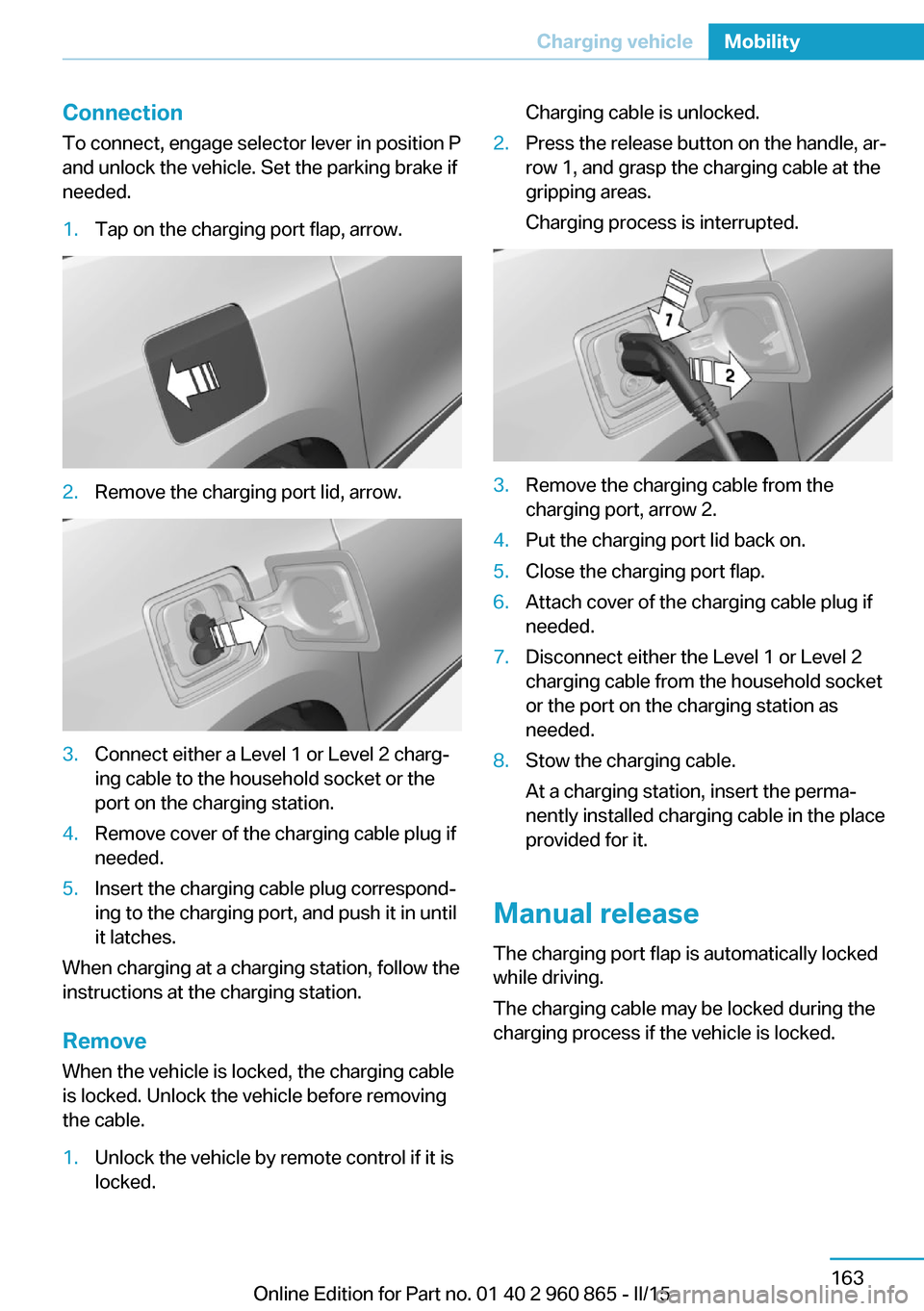
ConnectionTo connect, engage selector lever in position P
and unlock the vehicle. Set the parking brake if
needed.1.Tap on the charging port flap, arrow.2.Remove the charging port lid, arrow.3.Connect either a Level 1 or Level 2 charg‐
ing cable to the household socket or the
port on the charging station.4.Remove cover of the charging cable plug if
needed.5.Insert the charging cable plug correspond‐
ing to the charging port, and push it in until
it latches.
When charging at a charging station, follow the
instructions at the charging station.
Remove
When the vehicle is locked, the charging cable
is locked. Unlock the vehicle before removing
the cable.
1.Unlock the vehicle by remote control if it is
locked.Charging cable is unlocked.2.Press the release button on the handle, ar‐
row 1, and grasp the charging cable at the
gripping areas.
Charging process is interrupted.3.Remove the charging cable from the
charging port, arrow 2.4.Put the charging port lid back on.5.Close the charging port flap.6.Attach cover of the charging cable plug if
needed.7.Disconnect either the Level 1 or Level 2
charging cable from the household socket
or the port on the charging station as
needed.8.Stow the charging cable.
At a charging station, insert the perma‐
nently installed charging cable in the place
provided for it.
Manual release
The charging port flap is automatically locked
while driving.
The charging cable may be locked during the
charging process if the vehicle is locked.
Seite 163Charging vehicleMobility163
Online Edition for Part no. 01 40 2 960 865 - II/15
Page 180 of 236
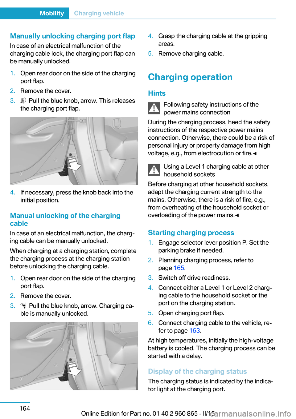
Manually unlocking charging port flapIn case of an electrical malfunction of the
charging cable lock, the charging port flap can
be manually unlocked.1.Open rear door on the side of the charging
port flap.2.Remove the cover.3. Pull the blue knob, arrow. This releases
the charging port flap.4.If necessary, press the knob back into the
initial position.
Manual unlocking of the charging
cable
In case of an electrical malfunction, the charg‐
ing cable can be manually unlocked.
When charging at a charging station, complete
the charging process at the charging station
before unlocking the charging cable.
1.Open rear door on the side of the charging
port flap.2.Remove the cover.3. Pull the blue knob, arrow. Charging ca‐
ble is manually unlocked.4.Grasp the charging cable at the gripping
areas.5.Remove charging cable.
Charging operation
Hints Following safety instructions of the
power mains connection
During the charging process, heed the safety
instructions of the respective power mains
connection. Otherwise, there could be a risk of
personal injury or property damage from high
voltage, e.g., from electrocution or fire.◀
Using a Level 1 charging cable at other
household sockets
Before charging at other household sockets,
adapt the charging current strength to the
mains. Otherwise, there is a risk of fire, e.g.,
from overheating of the household socket or
overloading of the power mains.◀
Starting charging process
1.Engage selector lever position P. Set the
parking brake if needed.2.Planning charging process, refer to
page 165.3.Switch off drive readiness.4.Connect either a Level 1 or Level 2 charg‐
ing cable to the household socket or the
port on the charging station.5.Open charging port flap.6.Connect charging cable to the vehicle, re‐
fer to page 163.
At high temperatures, initially the high-voltage
battery is cooled. The charging process can be
started with a delay.
Display of the charging status
The charging status is indicated by the indica‐
tor light at the charging port.
Seite 164MobilityCharging vehicle164
Online Edition for Part no. 01 40 2 960 865 - II/15
Page 184 of 236
Climate controlGeneral information
The following settings for climate control of
the vehicle are possible:▷Activate stationary climate control immedi‐
ately, refer to page 133.
With stationary climate control activated
and no charging cable connected, the
range is reduced.▷Planned climate control at the set depar‐
ture time, refer to page 134.
Discharged high-voltage and
vehicle battery
General information
In addition to the high-voltage battery, the ve‐
hicle has a 12 volt vehicle battery, which is re‐
quired for operation of the onboard electron‐
ics.
If the high-voltage battery and the vehicle bat‐
tery are discharged, it is not possible to oper‐
ate the vehicle.
Place vehicle in service To place the vehicle in service, charge as
usual.
If there is no possibility of charging on site,
contact the service center.
Charging vehicle with a discharged
vehicle battery
1.Unlock the vehicle, if needed, using the
integrated key, refer to page 38.2.Secure the vehicle against rolling.3.Manually unlock charging port flap if it is
locked, refer to page 163.4.Connect either a Level 1 or Level 2 charg‐
ing cable to the household socket or the
port on the charging station.5.Attach charging cable corresponding to
the charging socket connection.
Charging is started. The charging status is
not displayed. Do not open vehicle during
this time.
After several minutes, the vehicle is slightly
charged. The onboard electronics are ready
again. It is again possible to open the vehicle.
The charging status as well as the charging
state of the high-voltage battery can be dis‐
played again.
Continue charging vehicle until desired range
is possible.
If the vehicle battery cannot be charged, con‐
tact the service center.
Seite 168MobilityCharging vehicle168
Online Edition for Part no. 01 40 2 960 865 - II/15
Page 185 of 236
RefuelingVehicle features and options
This chapter describes all standard, country-
specific and optional features offered with the
series. It also describes features that are not
necessarily available in your car, e. g., due to
the selected options or country versions. This
also applies to safety-related functions and
systems. The respectively applicable country
provisions must be observed when using the
respective features and systems.
Hints Observe the fuel recommendation, refer to
page 172, prior to refueling.
A sufficient amount of fuel must be added to
operate the Range Extender. When the Range
Extender is activated, the current charging
state is maintained. The vehicle has a greater
range.
Do not refuel unless the engine is at a
standstill and the selector lever is in posi‐
tion P/N
Do not refuel unless the engine is at a standstill
and the selector lever is in position P/N, other‐
wise the buildup of pressure may cause the
fuel nozzle to shut off prematurely.◀
Tank vent
The concept The vehicle is equipped with a special fuel
tank. It is designed for special requirements
that arise in operation with the Range Ex‐
tender.General information
In the fuel tank, excess pressure can build up
due to gasoline vapors which are dissipated
before the tank lid is opened.
Overview
The button is located on the driver's footwell.
Tank venting1.Switch off drive readiness.2.
Press button to start the pressure
equalization.
The status of the tank venting is displayed
in the instrument cluster. In rare cases, the
tank venting can last several minutes.
If the tank venting has been completed, a
message is displayed in the instrument
cluster. The tank lid is released for open‐
ing.
3.Open the fuel filler flap.
If the fuel filler flap is not opened within 10
minutes after the fuel filler flap was re‐
leased, the fuel filler flap relocks. Press
button again.
Fuel lid
Opening
Before opening , vent the tank, refer to
page 169.
Seite 169RefuelingMobility169
Online Edition for Part no. 01 40 2 960 865 - II/15
Page 188 of 236
FuelVehicle features and optionsThis chapter describes all standard, country-
specific and optional features offered with the
series. It also describes features that are not
necessarily available in your car, e. g., due to
the selected options or country versions. This
also applies to safety-related functions and
systems. The respectively applicable country
provisions must be observed when using the
respective features and systems.
Fuel recommendation Note General fuel quality
Even fuels that conform to the specifica‐
tions can be of low quality. This may cause en‐
gine problems, for instance poor engine start-
up behavior, poor handling and/or poor
performance. Switch gas stations or use a
brand name fuel with a higher octane rating.◀
Gasoline For the best fuel efficiency, the gasoline
should be sulfur-free or very low in sulfur con‐
tent.
Fuels that are marked on the gas pump as con‐
taining metal must not be used.
Refuel only with unleaded gasoline with‐
out metallic additives.
Do not refuel with any leaded gasoline or gaso‐
line with metallic additives, e. g. manganese or
iron, as this can cause permanent damage to
the catalytic converter and other compo‐
nents.◀
Fuels with a maximum ethanol content of
10 %, i. e., E10, may be used for refueling.Ethanol should satisfy the following quality
standards:
US: ASTM 4806–xx
CAN: CGSB-3.511–xx
xx: comply with the current standard in each
case.
Do not use a fuel with a higher percent‐
age of ethanol
Do not use a fuel with a higher ethanol per‐
centage than recommended or one with other
types of alcohol, e.g. M5 to M100; otherwise
this could damage the engine and fuel supply
system.◀
Recommended fuel grade BMW recommends AKI 91.
Minimum fuel grade
BMW recommends AKI 89.
Minimum fuel grade
Do not use any gasoline below the mini‐
mum fuel grade as this may impair engine per‐
formance.◀
Fuel supply in winter Depending on the region, many gas stations
sell fuel that has been customized to winter or
summer conditions.
Fuel that is available in winter helps make a
cold start easier, e. g.
The manufacturer of the vehicle recommends
filling the tank with the corresponding fuel at
the start of winter to ensure the operational re‐
liability of the Range Extender at low tempera‐
tures.Seite 172MobilityFuel172
Online Edition for Part no. 01 40 2 960 865 - II/15
Page 189 of 236
Wheels and tiresVehicle features and options
This chapter describes all standard, country-
specific and optional features offered with the
series. It also describes features that are not
necessarily available in your car, e. g., due to
the selected options or country versions. This
also applies to safety-related functions and
systems. The respectively applicable country
provisions must be observed when using the
respective features and systems.
Tire inflation pressure Safety information
The tire characteristics and tire inflation pres‐
sure influence the following:▷The service life of the tires.▷Road safety.▷Driving comfort.
Checking the tire inflation pressure
Check the tire inflation pressure regularly
Regularly check the tire inflation pres‐
sure, and correct it as needed: at least twice a
month and before a long trip. If you fail to ob‐
serve this precaution, you may be driving on
tires with incorrect tire pressures, a condition
that may not only compromise your vehicle's
driving stability, but also lead to tire damage
and the risk of an accident.◀
Tires have a natural, consistent loss of tire in‐
flation pressure.
Tires heat up while driving, and the tire infla‐
tion pressure increases along with the tire's
temperature. The tire inflation pressure speci‐
fications relate to cold tires or tires with the
ambient temperature.
Only check the tire inflation pressure when the
tires are cold. This means after driving no more
than 1.25 miles/2 km or when the vehicle has
been parked for at least 2 hours.
The displays of inflation devices may under-
read by up to 1.45 psi/0.1 bar.
For Flat Tire Monitor: after correcting the tire
inflation pressure, reinitialize the Flat Tire
Monitor.
For Tire Pressure Monitor: after correcting the
tire inflation pressure, reset the Tire Pressure
Monitor.
Tire inflation pressure specifications
The tire inflation pressure table, refer to
page 174, contains all tire inflation pressure
specifications for the specified tire sizes at the
ambient temperature. Tire inflation pressure
specifications apply to approved tire sizes and
recommended tire brands. This information
can be obtained from your service center.
To identify the correct tire inflation pressure,
please note the following:▷Tire sizes of your vehicle.
Tire fill pressures
To achieve optimum driving comfort, note the
pressure specifications in the Tire inflation
pressure table, refer to page 174, and adjust
as needed.
Seite 173Wheels and tiresMobility173
Online Edition for Part no. 01 40 2 960 865 - II/15
Page 191 of 236
Uniform Tire Quality GradingQuality grades can be found where applicable
on the tire sidewall between tread shoulder
and maximum section width.
For example: Treadwear 200; Traction AA;
Temperature A
DOT Quality Grades
Treadwear
Traction AA A B C
Temperature A B C
All passenger car tires must conform to Fed‐
eral Safety Requirements in addition to these
grades.
TreadwearThe treadwear grade is a comparative rating
based on the wear rate of the tire when tested
under controlled conditions on a specified gov‐
ernment test course. For example, a tire
graded 150 would wear one and one-half, 1 g,
times as well on the government course as a
tire graded 100. The relative performance of
tires depends upon the actual conditions of
their use, however, and may depart signifi‐
cantly from the norm due to variations in driv‐
ing habits, service practices and differences in
road characteristics and climate.
Traction
The traction grades, from highest to lowest,
are AA, A, B, and C.
Those grades represent the tire's ability to
stop on wet pavement as measured under
controlled conditions on specified government
test surfaces of asphalt and concrete. A tire
marked C may have poor traction performance.
The traction grade assigned to this tire is
based on straight-ahead braking traction tests,
and does not include acceleration, cornering,
hydroplaning, or peak traction characteristics.Temperature
The temperature grades are A, the highest, B,
and C, representing the tire's resistance to the
generation of heat and its ability to dissipate
heat when tested under controlled conditions
on a specified indoor laboratory test wheel.
Sustained high temperature can cause the ma‐
terial of the tire to degenerate and reduce tire
life, and excessive temperature can lead to
sudden tire failure. The grade C corresponds
to a level of performance which all passenger
car tires must meet under the Federal Motor
Vehicle Safety Standard No. 109. Grades Band
A represent higher levels of performance on
the laboratory test wheel than the minimum re‐
quired by law.
Temperature grade for this tire
The temperature grade for this tire is es‐
tablished for a tire that is properly inflated and
not overloaded. Excessive speed, underinfla‐
tion, or excessive loading, either separately or
in combination, can cause heat buildup and
possible tire failure.
If necessary, have the vehicle towed.◀
M+S
Winter and all-season tires with better cold
weather performance than summer tires.
Tire tread
Summer tires
Do not drive with a tire tread depth of less than
0.12 in/3 mm.
There is an increased danger of hydroplaning if
the tire tread depth is less than 0.12 in/3 mm.
Winter tires
Do not drive with a tire tread depth of less than
0.16 in/4 mm.
Below a tread depth of 0.16 in/4 mm, tires are
less suitable for winter operation.Seite 175Wheels and tiresMobility175
Online Edition for Part no. 01 40 2 960 865 - II/15
Page 192 of 236
Minimum tread depth
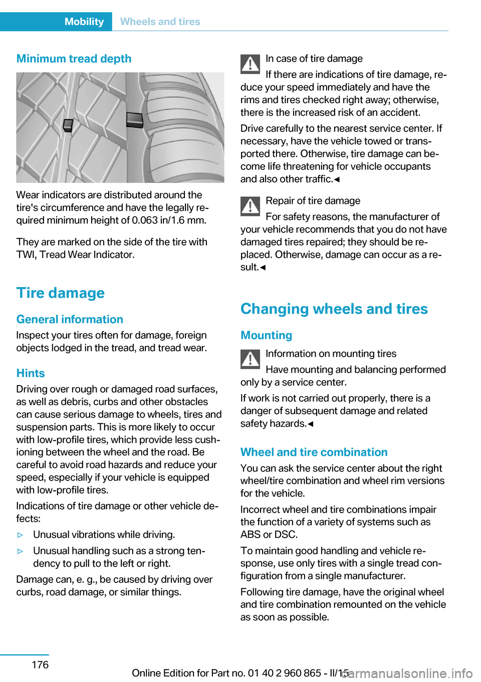
Wear indicators are distributed around the
tire's circumference and have the legally re‐
quired minimum height of 0.063 in/1.6 mm.
They are marked on the side of the tire with
TWI, Tread Wear Indicator.
Tire damage
General information
Inspect your tires often for damage, foreign
objects lodged in the tread, and tread wear.
Hints
Driving over rough or damaged road surfaces,
as well as debris, curbs and other obstacles
can cause serious damage to wheels, tires and
suspension parts. This is more likely to occur
with low-profile tires, which provide less cush‐
ioning between the wheel and the road. Be
careful to avoid road hazards and reduce your
speed, especially if your vehicle is equipped
with low-profile tires.
Indications of tire damage or other vehicle de‐
fects:
▷Unusual vibrations while driving.▷Unusual handling such as a strong ten‐
dency to pull to the left or right.
Damage can, e. g., be caused by driving over
curbs, road damage, or similar things.
In case of tire damage
If there are indications of tire damage, re‐
duce your speed immediately and have the
rims and tires checked right away; otherwise,
there is the increased risk of an accident.
Drive carefully to the nearest service center. If
necessary, have the vehicle towed or trans‐
ported there. Otherwise, tire damage can be‐
come life threatening for vehicle occupants
and also other traffic.◀
Repair of tire damage
For safety reasons, the manufacturer of
your vehicle recommends that you do not have
damaged tires repaired; they should be re‐
placed. Otherwise, damage can occur as a re‐
sult.◀
Changing wheels and tires
Mounting Information on mounting tires
Have mounting and balancing performed
only by a service center.
If work is not carried out properly, there is a
danger of subsequent damage and related
safety hazards.◀
Wheel and tire combination
You can ask the service center about the right
wheel/tire combination and wheel rim versions
for the vehicle.
Incorrect wheel and tire combinations impair
the function of a variety of systems such as
ABS or DSC.
To maintain good handling and vehicle re‐
sponse, use only tires with a single tread con‐
figuration from a single manufacturer.
Following tire damage, have the original wheel
and tire combination remounted on the vehicle
as soon as possible.Seite 176MobilityWheels and tires176
Online Edition for Part no. 01 40 2 960 865 - II/15