display BMW M2 COUPE 2016 Service Manual
[x] Cancel search | Manufacturer: BMW, Model Year: 2016, Model line: M2 COUPE, Model: BMW M2 COUPE 2016Pages: 220, PDF Size: 4.17 MB
Page 95 of 220
E.g. the sensors are unable to detect fog or
hazy weather. To avoid safety risks under
these conditions, you should always switch on
the lights manually.
Daytime running lights General information
Position of switch:
, ,
The daytime running lights light up when the
ignition is switched on. After the ignition is
switched off, the parking lights light up in posi‐
tion
.
Activating/deactivating In some countries, daytime running lights are
mandatory, so it may not be possible to deacti‐
vate the daytime running lights.
On the Control Display:
1."Settings"2."Lighting"3."Daytime running lamps"
Settings are stored for the profile currently
used.
Adaptive Light Control
The concept Adaptive Light Control is a variable headlight
control system that enables dynamic illumina‐
tion of the road surface.
General information
Depending on the steering angle and other pa‐
rameters, the light from the headlamp follows
the course of the road.
To avoid blinding oncoming traffic, the Adap‐
tive Light Control does not swivel to the driv‐
er's side when the vehicle is at a standstill.
Depending on the equipment version, Adap‐
tive Light Control consists of one or several
systems:▷Cornering light, refer to page 95.
Activating
Position of switch
with the ignition
switched on.
Cornering lights
The cornering lights are automatically
switched on depending on the steering angle
or the use of turn signals.
When driving in reverse, the cornering lights
may be automatically switched on regardless
of the steering angle.
Malfunction
A Check Control message is displayed.
Adaptive Light Control is malfunctioning or has
failed. Have the system immediately checked
by a dealer’s service center or another quali‐
fied service center or repair shop.
High-beam Assistant
The concept The high-beam Assistant detects other traffic
participants early on and automatically
switches the high beams on or off depending
on the traffic situation. The assistant ensures
that the high beams are switched on, when‐
ever the traffic situation allows. In the low
speed range, the high beams are not switched
on by the system.
General information The system responds to light from oncoming
traffic and traffic driving ahead of you, and to
adequate illumination, for example, in towns
and cities.
The driver can intervene at any time and switch
the high beams on and off as usual.
Seite 95LightsControls95
Online Edition for Part no. 01 40 2 970 518 - II/16
Page 97 of 220
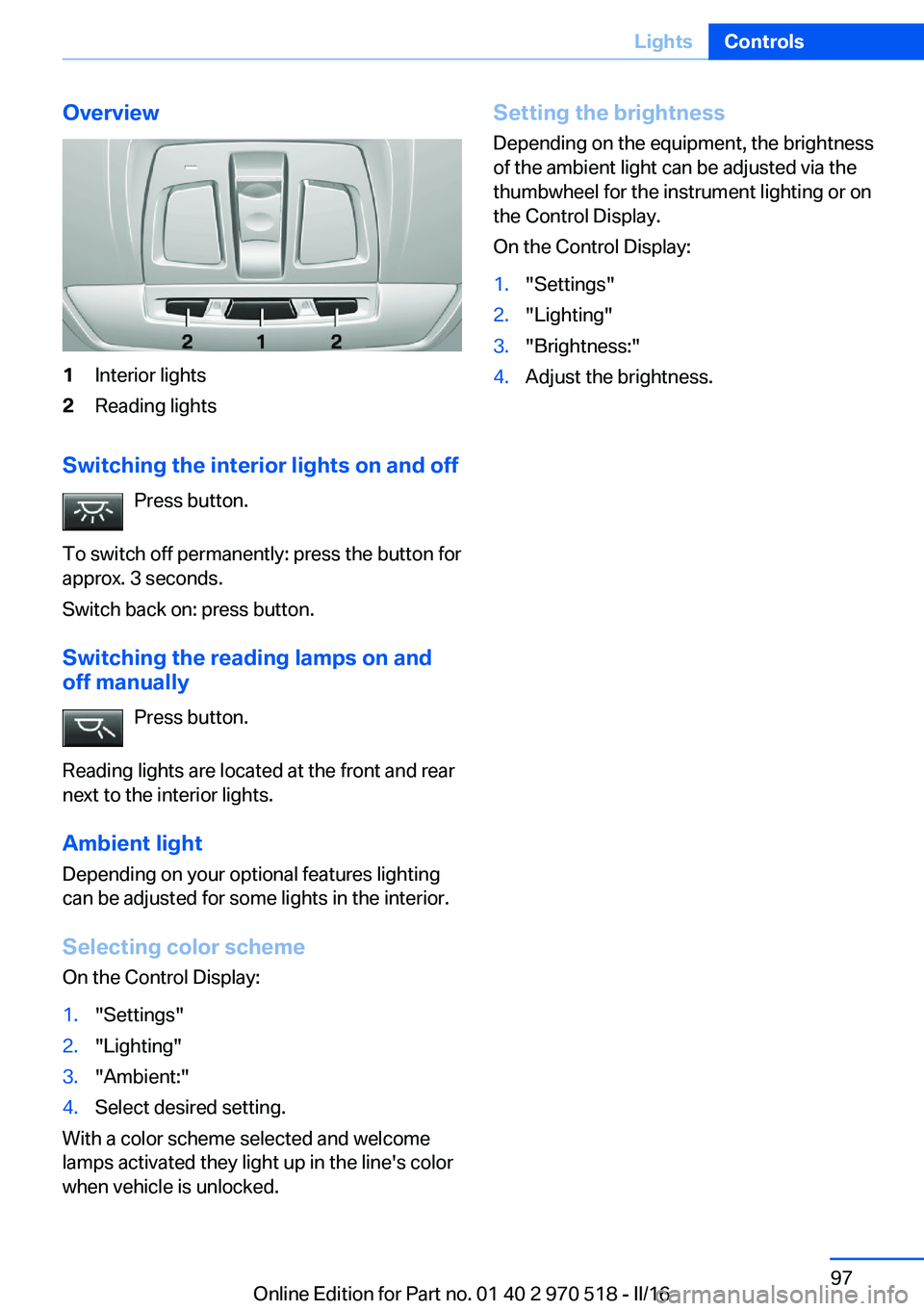
Overview1Interior lights2Reading lights
Switching the interior lights on and offPress button.
To switch off permanently: press the button for
approx. 3 seconds.
Switch back on: press button.
Switching the reading lamps on and off manually
Press button.
Reading lights are located at the front and rear
next to the interior lights.
Ambient light Depending on your optional features lighting
can be adjusted for some lights in the interior.
Selecting color scheme On the Control Display:
1."Settings"2."Lighting"3."Ambient:"4.Select desired setting.
With a color scheme selected and welcome
lamps activated they light up in the line's color
when vehicle is unlocked.
Setting the brightness
Depending on the equipment, the brightness
of the ambient light can be adjusted via the
thumbwheel for the instrument lighting or on
the Control Display.
On the Control Display:1."Settings"2."Lighting"3."Brightness:"4.Adjust the brightness.Seite 97LightsControls97
Online Edition for Part no. 01 40 2 970 518 - II/16
Page 101 of 220
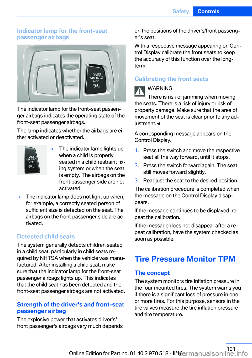
Indicator lamp for the front-seat
passenger airbags
The indicator lamp for the front-seat passen‐
ger airbags indicates the operating state of the
front-seat passenger airbags.
The lamp indicates whether the airbags are ei‐
ther activated or deactivated.
▷The indicator lamp lights up
when a child is properly
seated in a child restraint fix‐
ing system or when the seat
is empty. The airbags on the
front passenger side are not
activated.▷The indicator lamp does not light up when,
for example, a correctly seated person of
sufficient size is detected on the seat. The
airbags on the front passenger side are ac‐
tivated.
Detected child seats
The system generally detects children seated
in a child seat, particularly in child seats re‐
quired by NHTSA when the vehicle was manu‐ factured. After installing a child seat, make
sure that the indicator lamp for the front-seat
passenger airbags lights up. This indicates
that the child seat has been detected and the
front-seat passenger airbags are not activated.
Strength of the driver's and front-seat
passenger airbag
The explosive power that activates driver's/
front passenger's airbags very much depends
on the positions of the driver's/front passeng‐
er's seat.
With a respective message appearing on Con‐
trol Display calibrate the front seats to keep
the accuracy of this function over the long-
term.
Calibrating the front seats WARNING
There is risk of jamming when moving
the seats. There is a risk of injury or risk of
property damage. Make sure that the area of
movement of the seat is clear prior to any ad‐
justment.◀
A corresponding message appears on the
Control Display.1.Press the switch and move the respective
seat all the way forward, until it stops.2.Press the switch forward again. The seat
still moves forward slightly.3.Readjust the seat to the desired position.
The calibration procedure is completed when
the message on the Control Display disap‐
pears.
If the message continues to be displayed, re‐
peat the calibration.
If the message does not disappear after a re‐
peat calibration, have the system checked as
soon as possible.
Tire Pressure Monitor TPM
The concept The system monitors tire inflation pressure in
the four mounted tires. The system warns you
if there is a significant loss of pressure in one
or more tires. For this purpose, sensors in the
tire valves measure the tire inflation pressure
and tire temperature.
Seite 101SafetyControls101
Online Edition for Part no. 01 40 2 970 518 - II/16
Page 102 of 220
InformationWith use of the system observe further infor‐
mation found under Tire inflation pressure, re‐
fer to page 168.
Functional requirements
The system must have been reset with the
correct tire inflation pressure; otherwise, relia‐
ble signaling of tire inflation pressure loss is
not assured.
Reset the system after each adjustment of the
tire inflation pressure and after every tire or
wheel change.
Always use wheels with TPM electronics to
ensure that the system will operate properly.
Status display The current status of the Tire Pressure Moni‐
tor TPM can be displayed on the Control Dis‐
play, for example, whether or not the TPM is
active.1."Vehicle info"2."Vehicle status"3. "Tire Pressure Monitor (TPM)"
The status is displayed.
Status control display Tire and system status are indicated by the
color of the wheels and a text message on the
Control Display.
All wheels green System is active and will issue a warning rela‐
tive to the tire inflation pressures stored during
the last reset.
One wheel is yellow A flat tire or major drop in inflation pressure in
the indicated tire.
All wheels are yellow A flat tire or major drop in inflation pressure in
several tires.
Wheels, gray
The system cannot detect a flat tire due to a
malfunction.
Additional information The status control display additionally shows
the current tire inflation pressures and, de‐
pending on the model, tire temperatures. It
shows the actual values read; they may vary depending on driving style or weather condi‐
tions.
Carry out reset Reset the system after each adjustment of the
tire inflation pressure and after every tire or
wheel change.
On the Control Display and on the vehicle:1."Vehicle info"2."Vehicle status"3. "Perform reset"4.Start the engine - do not drive off.5.Reset tire inflation pressure: "Perform
reset".6.Drive away.
The wheels are displayed in gray and the sta‐
tus is displayed.
After driving faster than 19 mph/30 km/h for a
short period, the set tire inflation pressures are
accepted as reference values. The reset is
completed automatically while driving.
The progress of the reset is displayed.
After a successfully completed Reset, the
wheels on the Control Display are shown in
green and "Tire Pressure Monitor (TPM)
active" is displayed.
You may interrupt this trip at any time. When
you continue the reset resumes automatically.
Low tire pressure message The yellow warning lamp lights up. A
Check Control message is displayed.
Seite 102ControlsSafety102
Online Edition for Part no. 01 40 2 970 518 - II/16
Page 103 of 220
▷There is a flat tire or a major loss in tire in‐
flation pressure.▷No reset was performed for the system.
The system therefore issues a warning
based on the tire inflation pressures before
the last reset.1.Reduce your speed and stop cautiously.
Avoid sudden braking and steering maneu‐
vers.2.Identify the damaged wheel. Do so by
checking the tire inflation pressure using
the Mobility System. To correct the tire in‐
flation pressure.3.Repair flat tire with the Mobility System or
replace the damaged wheel.
A low tire inflation pressure might turn on DSC
Dynamic Stability Control.
Required tire inflation pressure check
message
A Check Control message is displayed in the
following situations
▷The system has detected a wheel change,
but no reset was done.▷Inflation was not carried out according to
specifications.▷The tire inflation pressure has fallen below
the level of the last confirmation.
In this case:
▷Check the tire pressure and correct as
needed.▷Carry out a reset of the system after a tire
change.
System limits
The system does not function properly if a re‐
set has not been carried out, for example, a flat
tire is reported though tire inflation pressures
are correct.
The tire inflation pressure depends on the
tire's temperature. Driving or exposure to the
sun will increase the tire's temperature, thus
increasing the tire inflation pressure. The tire
inflation pressure is reduced when the tire
temperature falls again. These circumstances
may cause a warning when temperatures fall
very sharply.
The system cannot indicate sudden serious
tire damage caused by external circumstances.
Malfunction The yellow warning lamp flashes and
then lights up continuously. A Check
Control message is displayed. No flat
tire or loss of tire inflation pressure can be de‐
tected.
Examples and recommendations in the follow‐
ing situations:▷A wheel without TPM electronics is
mounted: Have it checked by a dealer’s
service center or another qualified service
center or repair shop as needed.▷Malfunction: Have system checked by a
dealer’s service center or another qualified
service center or repair shop.▷TPM was unable to complete the reset.
Reset the system again.▷Interference through systems or devices
with the same radio frequency: After leav‐
ing the area of the interference, the system
automatically becomes active again.
Declaration according to NHTSA/
FMVSS 138 Tire Pressure Monitoring
System
Each tire, including the spare (if provided)
should be checked monthly when cold and in‐
flated to the inflation pressure recommended
by the vehicle manufacturer on the vehicle
placard or tire inflation pressure label. (If your
vehicle has tires of a different size than the size
indicated on the vehicle placard or tire inflation
pressure label, you should determine the
proper tire inflation pressure for those tires.)
As an added safety feature, your vehicle has
been equipped with a tire pressure monitoring
Seite 103SafetyControls103
Online Edition for Part no. 01 40 2 970 518 - II/16
Page 104 of 220

system (TPMS) that illuminates a low tire pres‐
sure telltale when one or more of your tires is
significantly under-inflated. Accordingly, when
the low tire pressure telltale illuminates, you
should stop and check your tires as soon as
possible, and inflate them to the proper pres‐
sure. Driving on a significantly under-inflated
tire causes the tire to overheat and can lead to
tire failure. Under-inflation also reduces fuel ef‐
ficiency and tire tread life, and may affect the
vehicle's handling and stopping ability. Please
note that the TPMS is not a substitute for
proper tire maintenance, and it is the driver's
responsibility to maintain correct tire pressure,
even if under-inflation has not reached the
level to trigger illumination of the TPMS low
tire pressure telltale. Your vehicle has also
been equipped with a TPMS malfunction indi‐
cator to indicate when the system is not oper‐
ating properly. The TPMS malfunction indica‐
tor is combined with the low tire pressure
telltale. When the system detects a malfunc‐
tion, the telltale will flash for approximately one
minute and then remain continuously illumi‐
nated. This sequence will continue upon sub‐
sequent vehicle start-ups as long as the mal‐
function exists. When the malfunction indicator
is illuminated, the system may not be able to
detect or signal low tire pressure as intended.
TPMS malfunctions may occur for a variety of
reasons, including the installation of replace‐
ment or alternate tires or wheels on the vehicle
that prevent the TPMS from functioning prop‐
erly. Always check the TPMS malfunction tell‐
tale after replacing one or more tires or wheels
on your vehicle to ensure that the replacement
or alternate tires and wheels allow the TPMS
to continue to function properly.
FTM Flat Tire Monitor The conceptThe system detects tire inflation pressure losson the basis of rotation speed differences be‐
tween the individual wheels while driving.In the event of a tire inflation pressure loss, the
diameter and therefore the rotational speed of
the corresponding wheel changes. This will be
detected and reported as a flat tire.
The system does not measure the actual infla‐
tion pressure in the tires.
Functional requirements
The system must have been initialized when
the tire inflation pressure was correct; other‐
wise, reliable flagging of a flat tire is not as‐
sured. Initialize the system after each correc‐ tion of the tire inflation pressure and after
every tire or wheel change.
Status display
The current status of the Flat Tire Monitor can
be displayed on the Control Display, for exam‐ ple, whether or not the FTM is active.1."Vehicle info"2."Vehicle status"3. "Flat Tire Monitor (FTM)"
The status is displayed.
Initialization
When initializing the once set inflation tire
pressures serve as reference values in order to
detect a flat tire. Initialization is started by con‐
firming the tire inflation pressures.
Do not initialize the system when driving with
snow chains.
On the Control Display:
1."Vehicle info"2."Vehicle status"3. "Perform reset"4.Start the engine - do not drive off.5.Start the initialization with "Perform reset".6.Drive away.
The initialization is completed while driving,
which can be interrupted at any time.
Seite 104ControlsSafety104
Online Edition for Part no. 01 40 2 970 518 - II/16
Page 105 of 220
The initialization automatically continues when
driving resumes.
Indication of a flat tire The yellow warning lamp lights up. A
Check Control message is displayed.
There is a flat tire or a major loss in tire
inflation pressure.1.Reduce your speed and stop cautiously.
Avoid sudden braking and steering maneu‐
vers.2.Identify the damaged wheel. Do so by
checking the tire inflation pressure using
the Mobility System. If the tire inflation
pressure in all tires is correct, the Flat Tire
Monitor may not have been initialized. In
this case, initialize the system.3.Repair flat tire with the Mobility System or
replace the damaged wheel.
System limits
A natural, even tire inflation pressure loss in all
four tires will not be recognized. Therefore,
check the tire inflation pressure regularly.
Sudden serious tire damage caused by exter‐
nal circumstances cannot be recognized in ad‐
vance.
The system could be delayed or malfunction in
the following situations:
▷When the system has not been initialized.▷When driving on a snowy or slippery road
surface.▷Sporty driving style: spinning traction
wheels, high lateral acceleration (drifting).▷When driving with snow chains.
Intelligent Safety
The concept
Intelligent Safety enables central operation of
the driver assistance system.
Depending on how the vehicle is equipped, In‐
telligent Safety consists of one or more sys‐
tems that can help prevent a imminent colli‐
sion. These systems are active automatically
every time the engine is started using the
Start/Stop button:▷Front-end collision warning with City Brak‐
ing function, refer to page 106.▷Pedestrian warning, refer to page 109.
Information
WARNING
Indicators and warnings do not relieve
the driver from personal responsibility. Due to
system limits, warnings or reactions of the sys‐
tem may not be output or they may be output
too late or incorrectly. There is risk of an acci‐
dent. Adjust the driving style to the traffic con‐
ditions. Watch traffic closely and actively inter‐
vene in the respective situations.◀
WARNING
Due to system limits, individual functions
can malfunction during tow-starting/towing
with the Intelligent Safety systems activated,
e.g., approach control warning with light brak‐
ing function. There is risk of an accident.
Switch all Intelligent Safety systems off prior to
tow-starting/towing.◀
Overview
Button in the vehicle
Intelligent Safety button
Seite 105SafetyControls105
Online Edition for Part no. 01 40 2 970 518 - II/16
Page 106 of 220
Camera
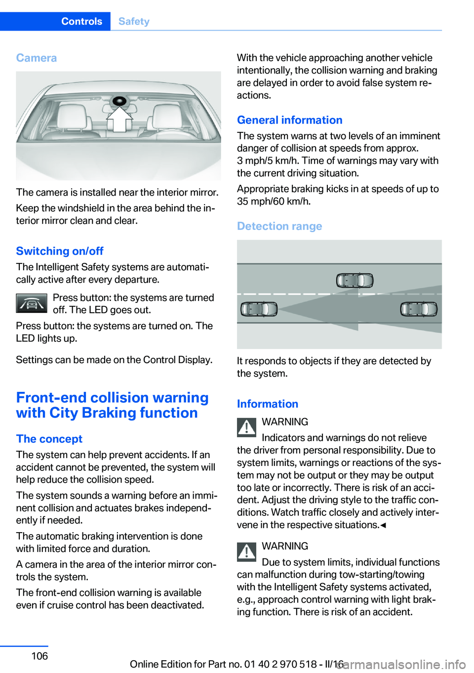
The camera is installed near the interior mirror.
Keep the windshield in the area behind the in‐
terior mirror clean and clear.
Switching on/off The Intelligent Safety systems are automati‐
cally active after every departure.
Press button: the systems are turned
off. The LED goes out.
Press button: the systems are turned on. The
LED lights up.
Settings can be made on the Control Display.
Front-end collision warning
with City Braking function
The concept The system can help prevent accidents. If an
accident cannot be prevented, the system will help reduce the collision speed.
The system sounds a warning before an immi‐
nent collision and actuates brakes independ‐
ently if needed.
The automatic braking intervention is done
with limited force and duration.
A camera in the area of the interior mirror con‐
trols the system.
The front-end collision warning is available
even if cruise control has been deactivated.
With the vehicle approaching another vehicle
intentionally, the collision warning and braking
are delayed in order to avoid false system re‐
actions.
General information
The system warns at two levels of an imminent
danger of collision at speeds from approx.
3 mph/5 km/h. Time of warnings may vary with
the current driving situation.
Appropriate braking kicks in at speeds of up to
35 mph/60 km/h.
Detection range
It responds to objects if they are detected by
the system.
Information WARNING
Indicators and warnings do not relieve
the driver from personal responsibility. Due to
system limits, warnings or reactions of the sys‐
tem may not be output or they may be output
too late or incorrectly. There is risk of an acci‐
dent. Adjust the driving style to the traffic con‐
ditions. Watch traffic closely and actively inter‐
vene in the respective situations.◀
WARNING
Due to system limits, individual functions
can malfunction during tow-starting/towing
with the Intelligent Safety systems activated,
e.g., approach control warning with light brak‐
ing function. There is risk of an accident.
Seite 106ControlsSafety106
Online Edition for Part no. 01 40 2 970 518 - II/16
Page 107 of 220
Switch all Intelligent Safety systems off prior to
tow-starting/towing.◀
Overview
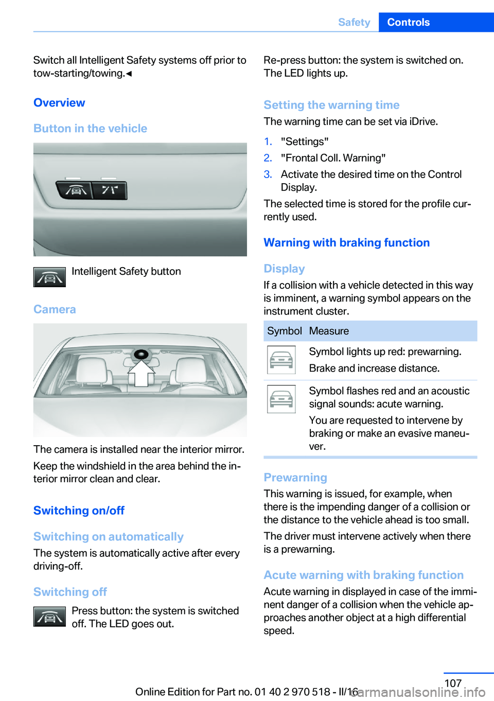
Button in the vehicle
Intelligent Safety button
Camera
The camera is installed near the interior mirror.
Keep the windshield in the area behind the in‐
terior mirror clean and clear.
Switching on/off
Switching on automatically The system is automatically active after every
driving-off.
Switching off Press button: the system is switched
off. The LED goes out.
Re-press button: the system is switched on.
The LED lights up.
Setting the warning time The warning time can be set via iDrive.1."Settings"2."Frontal Coll. Warning"3.Activate the desired time on the Control
Display.
The selected time is stored for the profile cur‐
rently used.
Warning with braking function
Display If a collision with a vehicle detected in this way
is imminent, a warning symbol appears on the
instrument cluster.
SymbolMeasureSymbol lights up red: prewarning.
Brake and increase distance.Symbol flashes red and an acoustic
signal sounds: acute warning.
You are requested to intervene by
braking or make an evasive maneu‐
ver.
Prewarning
This warning is issued, for example, when
there is the impending danger of a collision or
the distance to the vehicle ahead is too small.
The driver must intervene actively when there
is a prewarning.
Acute warning with braking function
Acute warning in displayed in case of the immi‐
nent danger of a collision when the vehicle ap‐
proaches another object at a high differential
speed.
Seite 107SafetyControls107
Online Edition for Part no. 01 40 2 970 518 - II/16
Page 108 of 220
The driver must intervene actively when there
is an acute warning. If necessary, the driver is
assisted by a minor automatic braking inter‐
vention in a possible risk of collision.
Acute warnings can also be triggered without
previous forewarning.
Braking intervention
The warning prompts the driver himself/herself
to react. During a warning, the maximum brak‐
ing force is used. Premise for the brake boos‐
ter is sufficiently quick and hard stepping on
the brake pedal. The system can assist with some braking intervention if there is a risk of a
collision. At low speeds vehicles may thus
come to a complete stop.
Manual transmission: During a braking inter‐
vention up to a complete stop, the engine may
be shut down.
The braking intervention is executed only if ve‐
hicle stability has not been restricted, e.g. by
deactivating the DSC Dynamic Stability Con‐
trol.
The braking intervention can be interrupted by
stepping on the accelerator pedal or by ac‐
tively moving the steering wheel.
Object detection can be restricted. Limitations
of the detection range and functional restric‐
tions are to be considered.
System limits
Information WARNING
The system can react incorrectly or not
at all due to the system limits. There is risk of
accidents or risk of property damage. Observe
the information regarding the system limits
and actively intervene, if needed.◀
Detection range
The system's detection potential is limited.Thus a system reaction might not come or
might come late.
E. g. the following situations may not be de‐
tected:▷Slow moving vehicles when you approach
them at high speed.▷Vehicles that suddenly swerve in front of
you, or sharply decelerating vehicles.▷Vehicles with an unusual rear appearance.▷Two-wheeled vehicles ahead of you.
Functional limitations
The system may not be fully functional in the
following situations:
▷In heavy fog, rain, sprayed water or snow‐
fall.▷In tight curves.▷If the driving stability control systems are
limited or deactivated, for example, DSC
OFF.▷If the field of view of the camera in the mir‐
ror is dirty or obscured.▷Up to 10 seconds after the start of the en‐
gine, via the Start/Stop button.▷During calibration of the camera immedi‐
ately after vehicle delivery.▷If there are constant blinding effects be‐
cause of oncoming light, e. g., from the sun
low in the sky.
Warning sensitivity
The more sensitive the warning settings are,
for example the warning time, the more warn‐
ings are displayed. However, there may also be
an excess of false warnings.
Seite 108ControlsSafety108
Online Edition for Part no. 01 40 2 970 518 - II/16