torque BMW M3 1992 E36 Workshop Manual
[x] Cancel search | Manufacturer: BMW, Model Year: 1992, Model line: M3, Model: BMW M3 1992 E36Pages: 759
Page 350 of 759
515-2
CENTRAL
LOCKING
AND
ANTI-THEFT
0013117
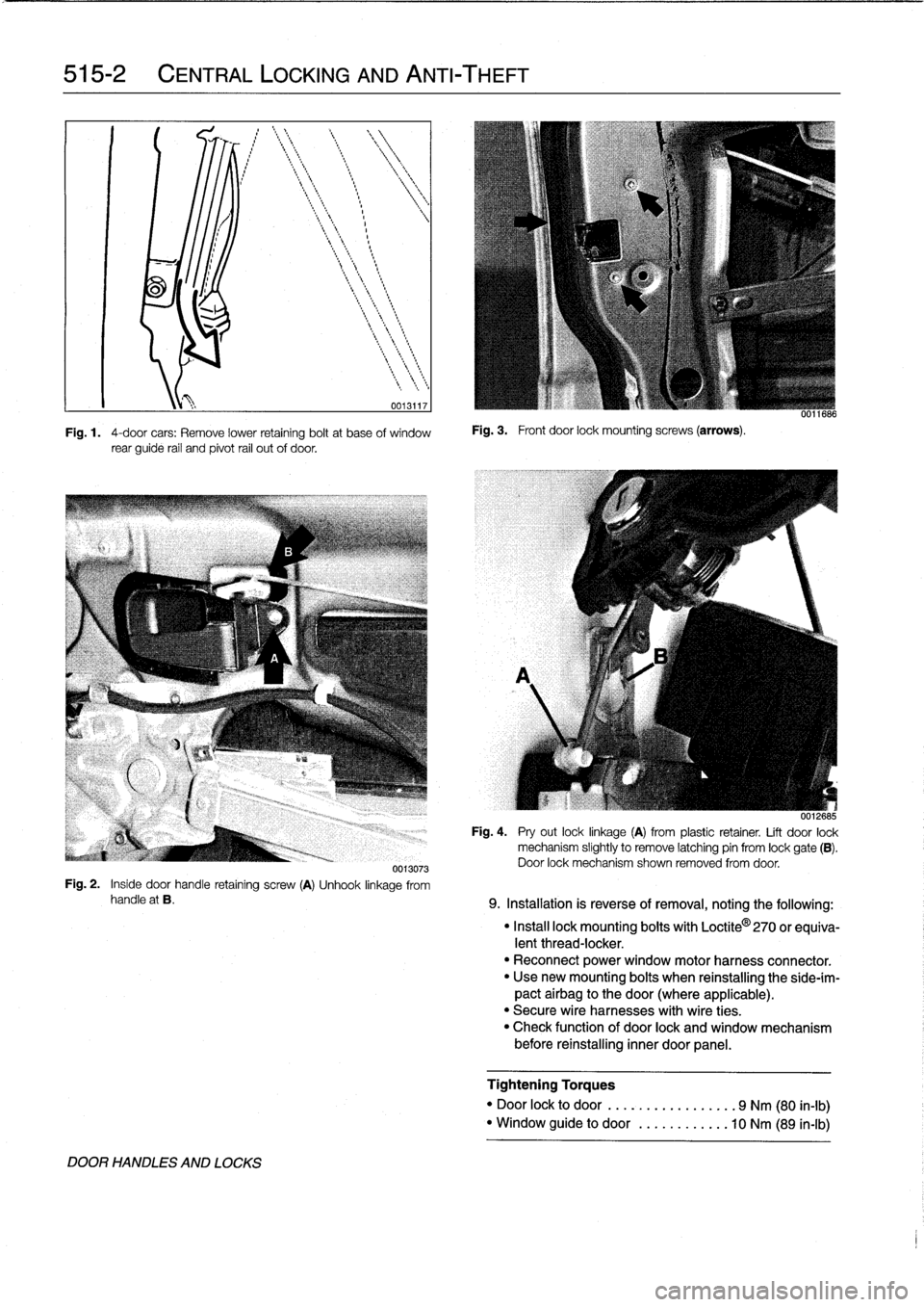
Fig
.
1
.
4-door
cars
:
Remove
lower
retaining
boltat
base
of
window
rear
guide
rail
and
pivot
rail
out
of
door
.
Fig
.
3
.
Front
door
lock
mounting
screws
(arrows)
.
uu11686
0012685
Fig
.
4
.
Pry
out
locklinkage
(A)
from
plastic
retainer
.
Lift
door
lock
mechanism
slightly
to
Rmove
latching
pin
from
lock
gate
(B)
.
Door
lock
mechanism
shown
removed
from
door
.
0013073
Fig
.
2
.
Inside
door
handle
retaining
screw
(A)
Unhook
linkage
from
handle
at
B
.
9
.
Installation
is
reverse
of
removal,
noting
the
following
:
DOOR
HANDLES
AND
LOCKS
"
Install
lock
mounting
bolts
with
Loctite
0
270
or
equiva-
lent
thread-locker
.
"
Reconnect
power
window
motor
harness
connector
.
"
Usenew
mounting
bolts
when
reinstalling
the
side-ím-
pact
airbag
to
the
door
(where
applicable)
.
"
Secure
wire
harnesses
with
wire
ties
.
"
Check
function
of
door
lock
and
window
mechanism
before
reinstalling
inner
door
panel
.
Tightening
Torques
"
Door
lock
to
door
......
.
..........
9
Nm
(80
in-lb)
"
Window
guide
to
door
........
.
...
10
Nm
(89
in-lb)
Page 352 of 759
515-4
CENTRAL
LOCKING
AND
ANTI-THEFT
11
.
Installation
is
reverse
of
removal
.
Keep
in
mind
the
fol-
4
.
Remove
screws
mounting
bottom
of
window
rear
track
lowing
:
to
door
.
See
Fig
.
9
.
"
Make
sure
rubber
seal
for
handle
is
correctly
posi-
tionedbefore
tightening
mounting
fasteners
.
"
Install
exteriortrim
piece
and
then
use
a
hooked
tool
to
pull
locking
plate
into
locked
position
.
Make
sure
door
handle
trim
contacts
body
evenly
before
locking
trim
in
place
.
"
Use
new
mounting
bolts
when
reinstalling
the
side-im-
pactairbag
to
the
door(where
applicable)
.
Reset
SRS
warning
light
and
clear
SRS
fault
memory
using
spe-
cial
test
equipment
.
See
721
Airbag
System
(SRS)
.
"
Reconnect
al¡
harness
connectors
(including
power
window
motor)before
installing
door
panel
.
"
Secure
wire
harnesses
withwire
ties
.
"
Adjust
and
reinitialize
windows
.
See
512
Door
Win-
dows
.
Tightening
Torque
"
Collar
nut
to
doorhandle
..........
10
Nm
(89
in-lb)
1.
Remove
rear
door
panel
and
vapor
barrier
as
described
in
411
Doors
.
2
.
Remove
window
from
rear
dooras
described
in
512
Door
Windows
.
3
.
Disconnect
andremove
inside
door
handle
.
See
Fig
.
8
.
0013073
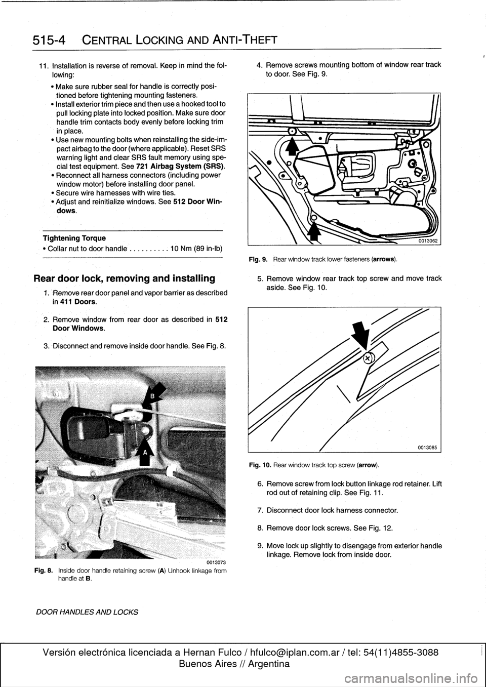
Fig
.
8
.
Inside
door
handle
retaining
screw
(A)
Unhook
linkage
from
handle
at
B
.
DOOR
HANDLES
AND
LOCKS
Fig
.
9
.
Rear
window
track
lower
fasteners
(arrows)
.
Reardoor
lock,
removing
and
installing
5
.
Remove
window
rear
track
top
screw
and
move
track
aside
.
See
Fig
.
10
.
Fig
.
10
.
Rear
window
track
top
screw
(arrow)
.
6
.
Remove
screw
from
lock
button
linkage
rod
retainer
.
Lift
rod
out
of
retaining
clip
.
See
Fig
.
11
.
7
.
Disconnect
door
lock
harnessconnector
.
8
.
Remove
door
lock
screws
.
See
Fig
.
12
.
0013085
9
.
Move
lock
upslightly
to
disengage
from
exterior
handle
linkage
.
Remove
lock
from
inside
door
.
Page 353 of 759
0011688
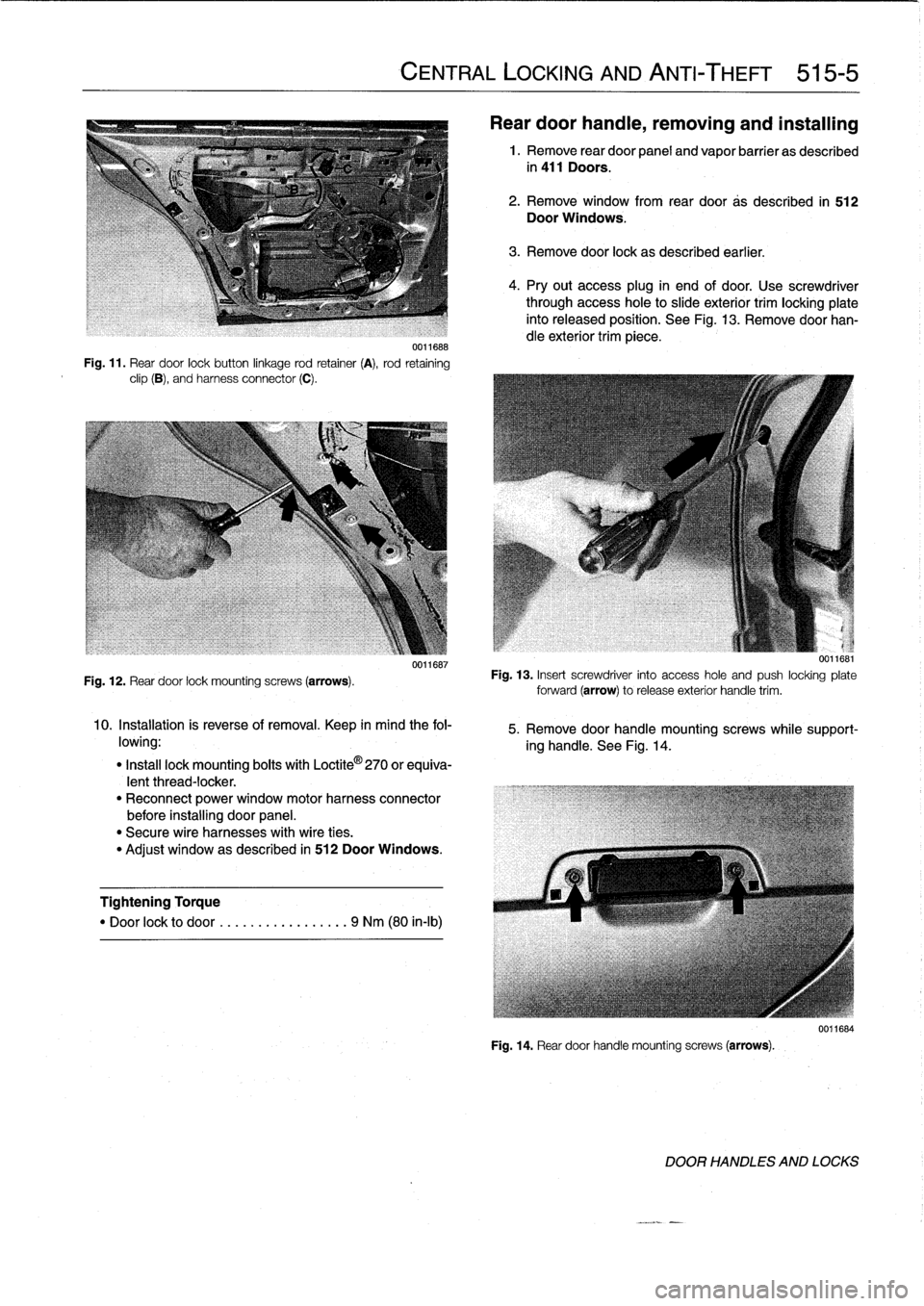
Fig
.
11
.
Rear
door
lockbutton
linkage
rod
retainer
(A),
rod
retaining
clip
(B),
and
harness
connector
(C)
.
Fig
.
12
.
Rear
door
lock
mounting
screws
(arrows)
.
0011687
10
.
Installation
is
reverse
of
removal
.
Keep
in
mind
the
fol-
lowing
:
"
Insta¡¡
lock
mounting
boits
with
Loctite
©
270
or
equiva-
lentthread-locker
.
"
Reconnect
power
window
motorharness
connector
before
installing
door
panel
.
"
Secure
wire
harnesses
with
wire
ties
.
"
Adjust
window
as
described
in
512
Door
Windows
.
Tightening
Torque
"
Door
lock
to
door
.
...
.
..
..........
9
Nm
(80
in-lb)
CENTRAL
LOCKING
AND
ANTI-THEFT
515-5
Rear
door
handie,
removing
and
installing
1
.
Remove
rear
door
panel
and
vapor
barrier
as
described
in
411
Doors
.
2
.
Remove
window
from
rear
door
as
described
in
512
Door
Windows
.
3
.
Remove
door
lock
as
described
earlier
.
4
.
Pry
out
access
plug
in
end
of
door
.
Use
screwdriver
through
access
hole
to
slide
exterior
trim
locking
plate
into
released
position
.
See
Fig
.
13
.
Remove
doorhan-
dle
exterior
trim
piece
.
u
.]lbbl
Fig
.
13
.
Insert
screwdriver
into
access
hole
and
push
locking
plate
forward
(arrow)torelease
exterior
handle
trim
.
5
.
Remove
door
handle
mountingscrews
while
support-
ing
handle
.
See
Fig
.
14
.
Fig
.
14
.
Reardoor
handle
mounting
screws
(arrows)
.
0011684
DOOR
HANDLES
AND
LOCKS
Page 354 of 759
515-6
CENTRAL
LOCKING
AND
ANTI-THEFT
6
.
Remove
door
handle
assembly
from
inside
door
.
7
.
Installation
is
reverse
of
removal
.
Keep
in
mindthe
fol-
lowing
:
"
Make
sure
rubber
seal
for
handle
is
correctly
posi-
tionedbefore
tightening
mounting
fasteners
.
"
Install
exterior
trim
piece
and
then
use
a
hooked
toolto
pull
locking
plate
into
locked
position
.
Make
sure
door
handle
trim
contacts
body
evenly
before
lockingtrim
in
place
.
"
Reconnect
all
harness
connectors
(including
power
window
motor)before
installing
door
panel
.
"
Secure
wire
harnesses
withwire
ties
.
"
Adjust
windowas
described
in
512
Door
Windows
.
Tightening
Torque
"
Rear
door
handle
mounting
screws
..
10
Nm
(89
in-lb)
NOTE
If
the
striker
backup
plate
fafls
into
the
body
cavlty,
it
can
be
retrieved
after
removing
the
inside
trim
from
the
B-pillar
(door-post
pillar)
.
Tightening
Torque
"
Striker
plate
to
body
pillar
..........
28
Nm
(20
ft-lb)
LOCKING
ACTUATORS
Door
Locking
Actuator
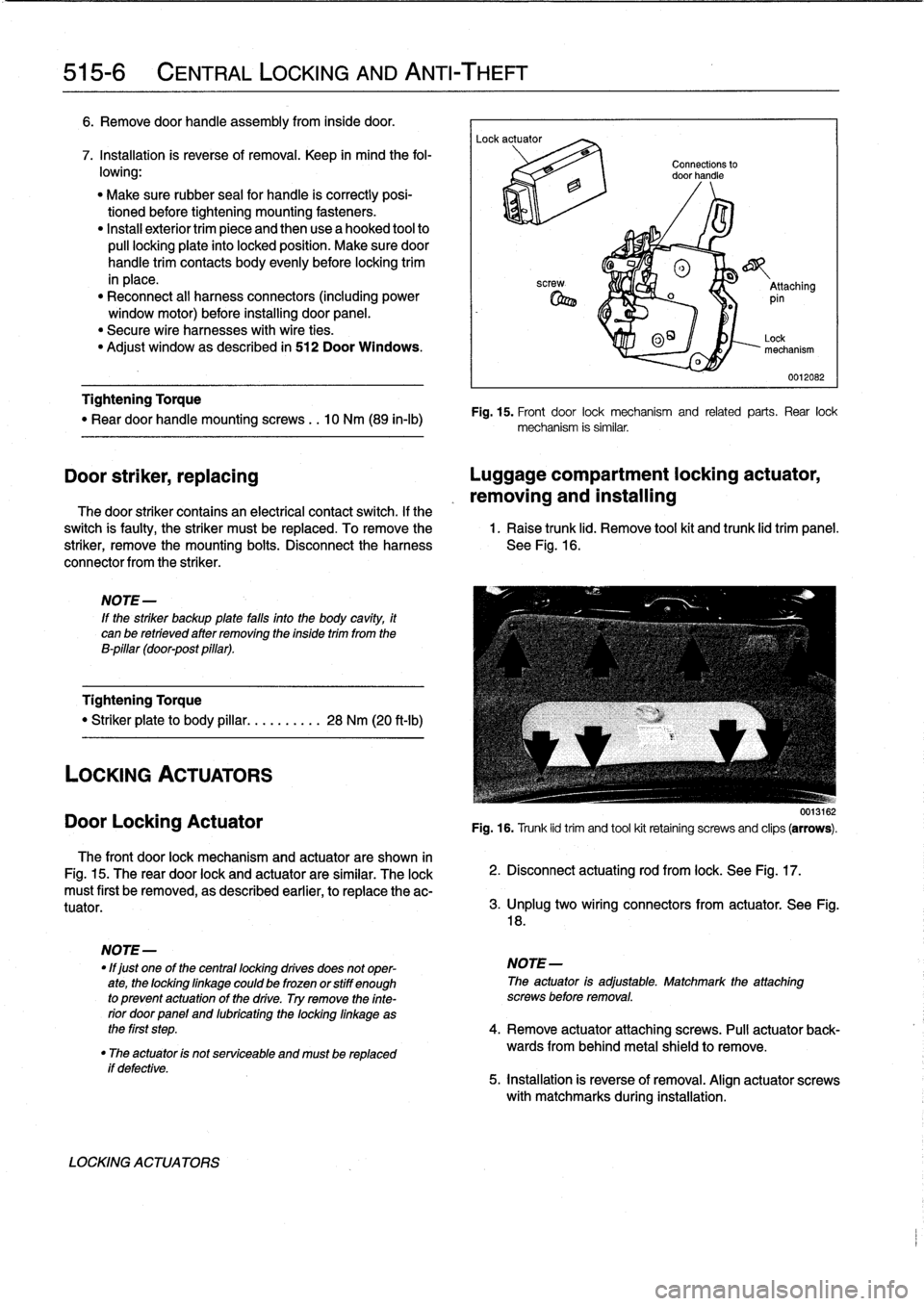
The
front
door
lock
mechanism
and
actuator
are
shown
in
Fig
.
15
.
The
rear
door
lock
and
actuator
are
similar
.
The
lock
must
first
be
removed,
as
described
earlier,
to
replace
the
ac-
tuator
.
if
defective
.
LOCKING
ACTUATORS
Connections
to
door
handle
®
o
_
Attaching
pin
0
O~
Lock
mechanism
0012082
Fig
.
15
.
Front
door
lock
mechanism
and
related
parts
.
Rear
lock
mechanism
is
similar
.
Door
striker,
replacing
Luggage
compartment
locking
actuator,
removing
and
installing
The
door
striker
contains
an
electrical
contact
switch
.
If
the
switch
is
faulty,
the
striker
must
be
replaced
.
To
remove
the
1
.
Raise
trunk
lid
.
Remove
tool
kit
and
trunk
lid
trim
panel
.
striker,
remove
the
mounting
bolts
.
Disconnect
the
harness
See
Fig
.
16
.
connector
from
the
striker
.
0013162
Fig
.
16
.
Trunk
lid
trim
and
tool
kit
retainíng
screws
and
clips
(arrows)
.
2
.
Disconnect
actuating
rod
from
lock
.
See
Fig
.
17
.
3
.
lJnplug
two
wíring
connectors
from
actuator
.
See
Fig
.
18
.
NOTE
-
"
lf
just
one
of
the
centrallocking
drives
does
not
oper-
NOTE-
ate,
the
lockinglinkage
could
be
frozen
orstiff
enough
The
actuator
is
adjustable
.
Matchmark
the
attaching
to
prevent
actuatonof
the
drive
.
Try
remove
the
finte-
screws
before
removal
.
rior
doorpanel
and
lubricating
the
locking
linkage
as
the
first
step
.
4
.
Remove
actuator
attaching
screws
.
Pull
actuator
back-
"
The
actuator
is
not
serviceable
and
mustbe
replaced
wards
from
behind
metal
shield
to
remove
.
5
.
installation
is
reverse
of
removal
.
Align
actuator
screws
with
matchmarks
during
installation
.
Page 362 of 759
520-2
S
EATS
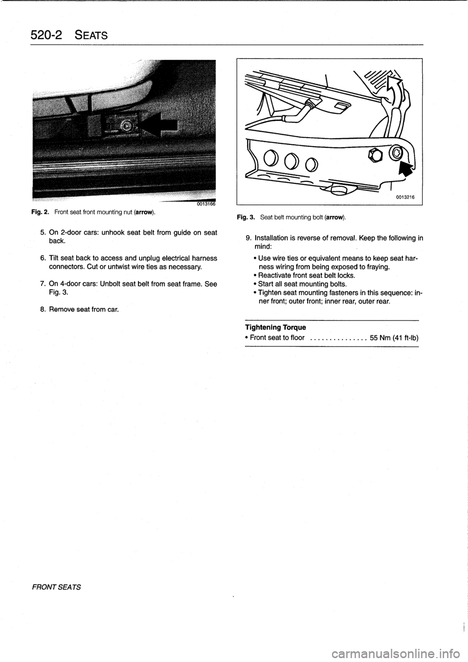
Fig
.
2
.
Frontseat
front
mounting
nut
(arrow)
.
FRONT
SEA
TS
0013166
5
.
On
2-door
cars
:
unhook
seat
belt
from
guide
on
seat
back
.
8
.
Remove
seatfrom
car
.
Fig
.
3
.
Seat
belt
mounting
bolt
(arrow)
.
0013216
9
.
Installation
is
reverse
of
removal
.
Keep
the
following
in
mind
:
6
.
Tilt
seat
back
to
access
and
unplug
electrical
harness
"
Use
wire
ties
orequivalent
means
to
keep
seat
har
connectors
.
Cut
or
untwist
wire
ties
as
necessary
.
ness
wiring
from
being
exposed
to
fraying
.
"
Reactivate
front
seat
belt
locks
.
7
.
On
4-door
cars
:
Unbolt
seat
belt
from
seat
frame
.
See
"
Start
all
seat
mounting
boits
.
Fig
.
3
.
"
Tighten
seat
mounting
fasteners
in
thís
sequence
:
in-
ner
front
;
outer
front
;
inner
rear,
outer
rear
.
Tightening
Torque
"
Front
seat
to
floor
........
.......
55
Nm
(41
ft-Ib)
Page 369 of 759
4
.
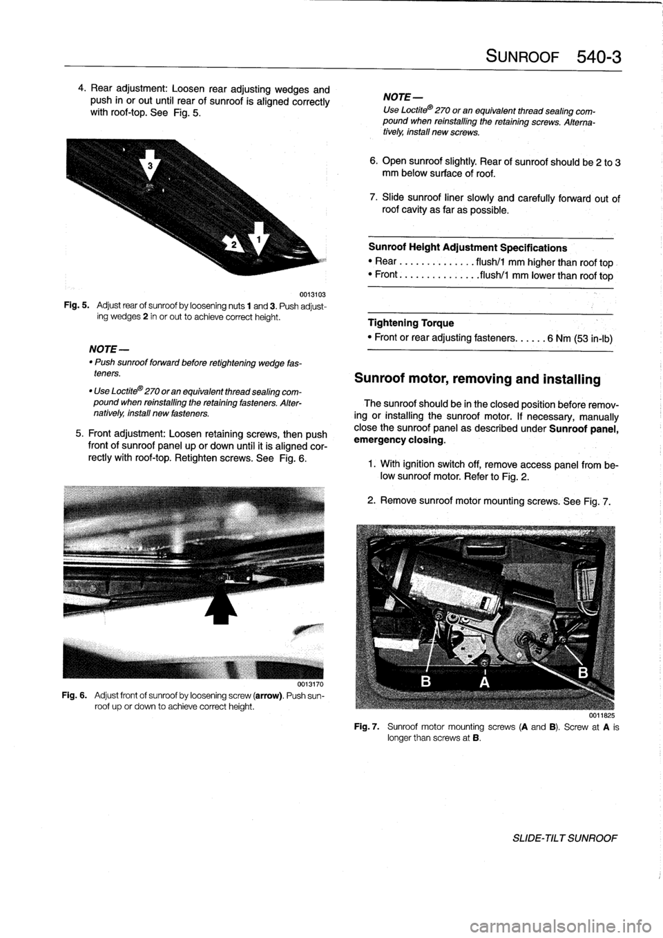
Rear
adjustment
:
Loosen
rear
adjusting
wedges
and
push
in
or
out
until
rear
of
sunroof
is
aligned
correctly
withroof-top
.
See
Fig
.
5
.
0013103
Fig
.
5
.
Adjust
rear
of
sunroof
by
loosening
nuts
1
and3
.
Push
adjust-
íng
wedges2
in
or
out
to
achieve
correctheight
.
NOTE-
"
Push
sunroofforward
before
retightening
wedge
fas-
teners
.
0013170
Fig
.
6
.
Adjust
front
of
sunroof
by
loosening
screw
(arrow)
.
Push
sun-
roof
up
or
down
to
achieve
correctheight
.
SUNROOF
540-
3
NOTE-
Use
Loctite®
270
or
an
equivalent
thread
sealing
com-
pound
when
reinstalling
theretaining
screws
.
Alterna-
tively,
install
new
screws
.
6
.
Open
sunroof
slightly
.
Rear
of
sunroofshould
be2
to
3
mm
below
surface
of
roof
.
7
.
Slide
sunroof
liner
slowly
and
carefully
forward
out
of
roof
cavity
as
far
as
possible
.
Sunroof
Height
Adjustment
Specifications
"
Rear
........
....
.
.
flush/1
mm
higher
than
roof
top
"
Front
...
..
.
....
..
.
..
flush/l
mm
lower
than
roof
top
Tightening
Torque
"
Front
orrear
adjusting
fasteners
...
...
6
Nm
(53
in-lb)
Sunroof
motor,
removing
and
installing
"
Use
Loctite®270
oran
equivalent
thread
sealing
com-
pound
when
reinstalling
the
retaining
fasteners
.
Alter-
The
sunroofshould
be
in
theclosed
posítion
before
remov-
natively,install
new
fasteners
.
ing
or
installing
the
sunroof
motor
.
If
necessary,
manually
5
.
Front
adjustment
:
Loosen
retaining
screws,
then
push
close
the
sunroof
panel
as
described
under
Sunroof
panel,
frontof
sunroof
panel
up
or
down
until
it
is
aligned
cor-
emergency
ciosing
.
rectly
with
roof-top
.
Retighten
screws
.
See
Fig
.
6
.
1
.
With
ignition
switch
off,
Rmove
access
panel
from
be-low
sunroof
motor
.
Refer
to
Fig
.
2
.
2
.
Remove
sunroof
motormountingscrews
.
See
Fig
.
7
.
0011825
Fig
.
7
.
Sunroof
motor
mountingscrews
(A
and
B)
.
Screw
at
A
is
longer
than
screws
at
B
.
SLIDE-TILT
SUNROOF
Page 370 of 759
540-
4
SUNROOF
3
.
Disconnect
harness
connector
from
motor
and
remove
motor
.
4
.
Installation
is
reverse
of
removal
.
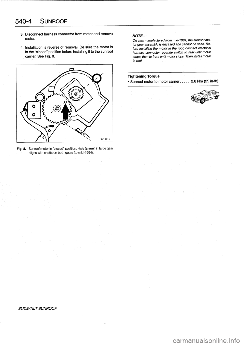
Be
sure
the
motor
is
in
the
"closed"
position
before
installing
it
to
the
sunroof
carrier
.
See
Fig
.
8
.
SLIDE-TILT
SUNROOF
0011813
Fig
.
8
.
Sunroof
motor
in
"closed"
position
.
Hole
(arrow)
in
large
gear
aligns
with
shafts
on
both
gears
(to
mid-1994)
.
NOTE-
On
cars
manufacturedfrom
mid-1994,
the
sunroof
mo-
tor
gearassembly
is
encased
and
cannot
be
seen
.
Be-
fore
installing
the
motor
in
the
roof,
connect
electrical
harness
connector,
operate
switch
to
rear
until
motor
stops,
then
to
front
until
motor
stops
.
Then
install
motor
in
roof
.
Tightening
Torque
"
Sunroof
motor
to
motor
carrier
.
.
.
.
.
2
.8
Nm
(25
in-lb)
Page 377 of 759
Convertible
top
drive
motor,
replacing
5
.
Working
in
convertible
top
storage
compartment
be-
hind
driver's
seat,
remove
convertible
top
linkage
rods
1
.
Open
convertible
top
partially,
stopping
when
convert-
from
top
of
motor
.
Refer
to
Fig
.
11
.
ible
top
lid
is
fully
upen
.
Remove
lid
.
2
.
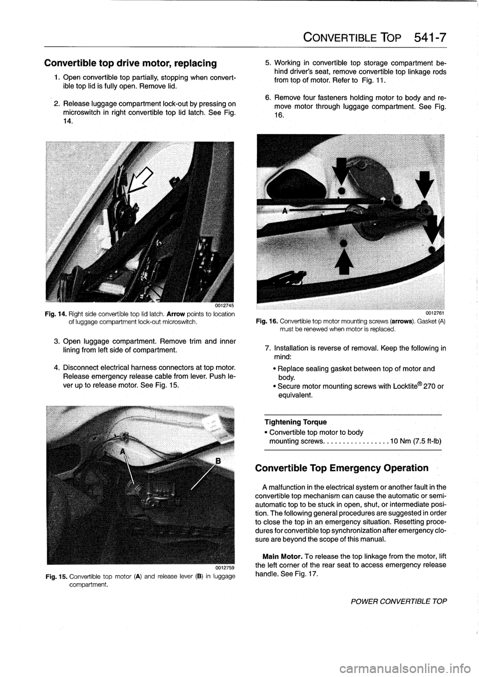
Release
luggage
compartment
lock-out
by
pressing
on
microswitch
in
right
convertible
top
lid
latch
.
See
Fig
.
14
.
0012745
Fig
.
14
.
Rightside
convertible
top
lid
latch
.
Arrow
points
to
location
of
luggage
compartment
lock-out
microswitch
.
3
.
Open
luggage
compartment
.
Remove
trim
and
inner
lining
from
left
side
of
compartment
.
4
.
Disconnect
electrical
harness
connectors
at
top
motor
.
Release
emergency
release
cable
from
lever
.
Push
le-
ver
up
to
release
motor
.
See
Fig
.
15
.
uu12759
Fig
.
15
.
Convertible
top
motor
(A)
and
release
lever
(B)
in
luggage
compartment
.
CONVERTIBLE
TOP
541-
7
6
.
Remove
four
fastenersholding
motor
to
body
and
re-
move
motor
through
luggage
compartment
.
See
Fig
.
16
.
0012761
Fig
.
16
.
Convertible
top
motor
mountingscrews
(arrows)
.
Gasket
(A)
mustbe
renewed
when
motor
is
replaced
.
7
.
Installation
is
reverse
of
removal
.
Keep
the
following
in
mind
:
"
Replace
sealing
gasket
between
top
of
motor
and
body
.
"
Securemotormountingscrews
with
Locktite
®
270
or
equivalent
.
Tightening
Torque
"
Convertible
top
motor
to
body
mountingscrews
...
...
.
.
.........
10
Nm
(7
.5
ft-Ib)
Convertible
Top
Emergency
Operation
A
malfunction
in
the
electrical
system
or
another
fault
in
the
convertible
top
mechanism
can
cause
the
automatic
or
semi-
automatic
top
to
be
stuck
in
open,
shut,
or
intermediate
posi-
tion
.
The
following
general
procedures
are
suggested
in
order
to
close
the
top
in
an
emergency
situation
.
Resetting
proce-
dures
for
convertible
top
synchronization
after
emergency
clo-
sure
are
beyond
the
scope
of
this
manual
.
Main
Motor
.
To
release
thetop
linkage
from
the
motor,
lift
the
left
comer
of
the
rearseat
to
access
emergency
release
handle
.
See
Fig
.
17
.
POWER
CONVERTIBLE
TOP
Page 421 of 759
4
.
Installation
is
reverse
of
removal
.
Recheck
wiper
arm
tightening
torque
after
waiting
15minutes
.
Tightening
Torque
"
Wiper
arm
to
wiper
shaft
..........
25
Nm
(18
ft-Ib)
WINDSHIELD
WIPER
ASSEMBLY
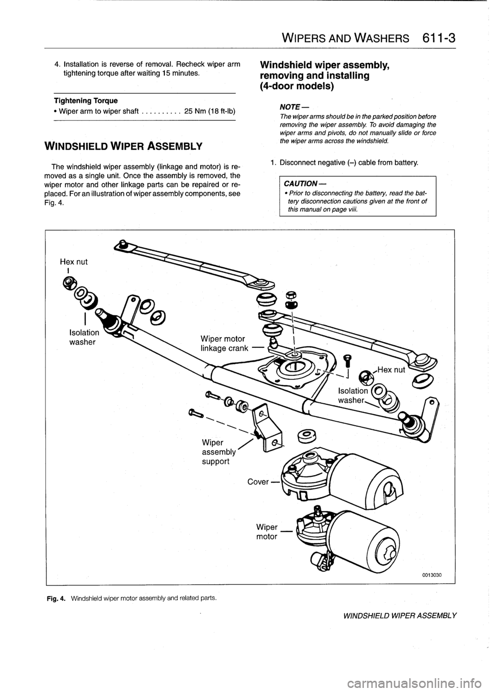
The
windshield
wiper
assembly
(linkage
and
motor)
is
re-
moved
asa
single
unit
.
Once
the
assembly
is
removed,
the
wiper
motor
and
other
linkage
parts
can
be
repairedor
re-
placed
.
Foran
illustration
of
wiper
assembly
components,
see
Fig
.
4
.
Hex
nut
I
J
Wiper
motor
Fig
.
4
.
Windshield
wiper
motor
assembly
and
related
parts
.
WIPERS
AND
WASHERS
611-
3
Windshield
wiperassembly,
removing
and
installing
(4-door
modeis)
1
.
Disconnect
negative
(-)
cable
from
battery
.
NOTE
-
Thewiperarms
should
be
in
the
parked
position
before
removing
the
wiper
assembly
.
To
avoid
damaging
the
wiper
arms
and
pivots,
do
not
manually
slide
or
force
the
wiper
arms
across
the
windshield
.
CAUTION
-
"
Prior
to
disconnectiog
the
battery,
read
the
bat-
tery
disconnection
cautions
given
at
the
front
of
this
manual
on
page
viii
.
0013030
WINDSHIELD
WIPER
ASSEMBLY
Page 423 of 759
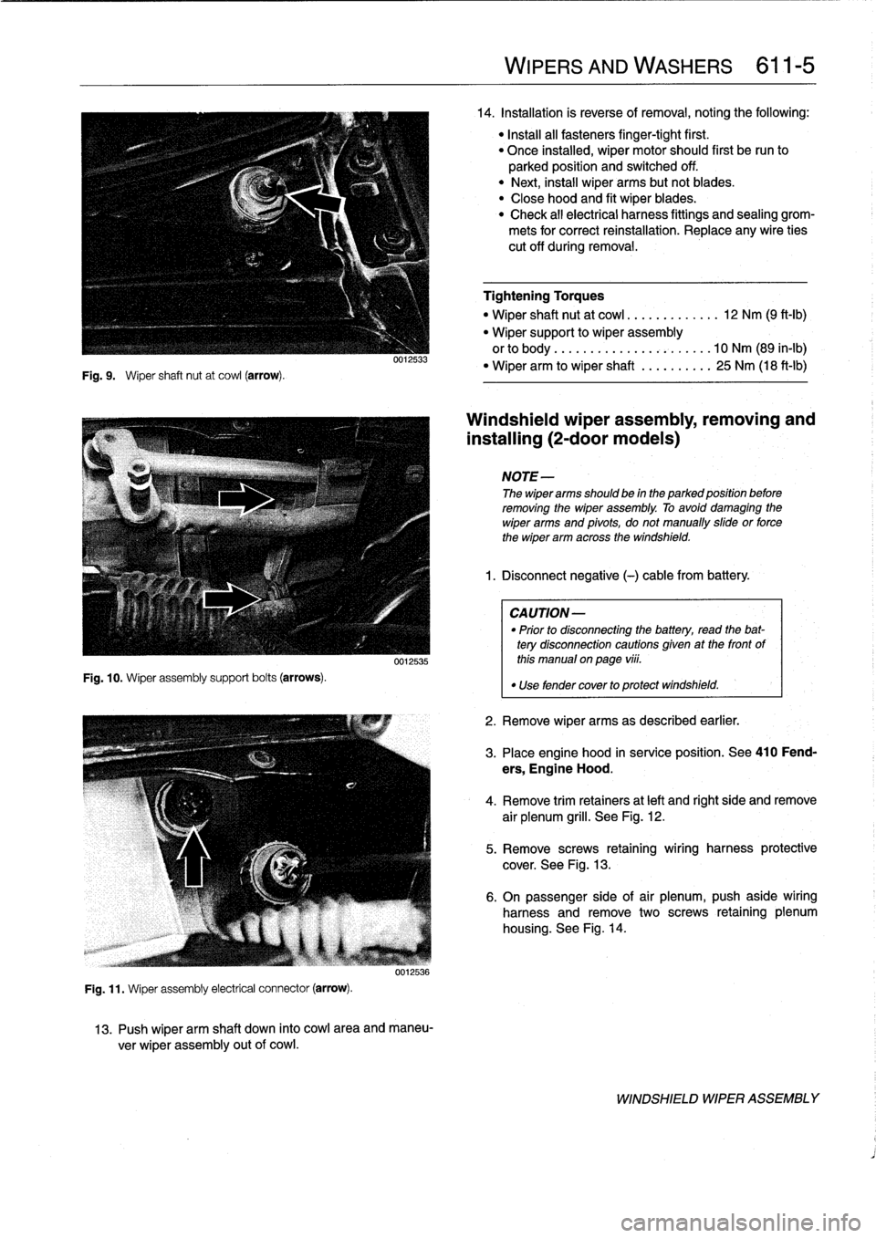
Fig
.
9
.
Wiper
shaft
nut
at
cowl
(arrow)
.
Fig
.
10
.
Wiper
assembly
support
bolts
(arrows)
.
0012533
0012535
Fig
.
11
.
Wiper
assembly
electrical
connector
(arrow)
.
0012536
13
.
Push
wiper
arm
shaft
down
into
cowl
area
and
maneu-
ver
wiper
assembly
out
of
cowl
.
WIPERS
AND
WASHERS
611-
5
14
.
Installation
is
reverse
of
removal,noting
the
following
:
"
Install
all
fasteners
finger-tight
first
.
"
Once
installed,
wiper
motor
should
first
be
run
to
parked
position
and
switched
off
.
"
Next,
instaf
wiper
arms
butnotblades
.
"
Close
hood
and
fit
wiper
blades
.
"
Check
all
electrical
harness
fittings
and
sealing
grom-
mets
for
correct
reinstallation
.
Replace
any
wire
ties
cut
off
during
removal
.
Tightening
Torques
"
Wiper
shaft
nut
at
cowl
.............
12
Nm
(9
ft-Ib)
"
Wiper
support
to
wiper
assembly
orto
body
..
..
..
.
...............
10
Nm
(89
in-lb)
"
Wiper
arm
to
wiper
shaft
..........
25
Nm
(18
ft-lb)
Windshieldwiper
assembly,
removing
and
installing
(2-door
modeis)
NOTE-
The
wiper
arms
should
be
in
the
parked
position
before
removing
the
wiper
assembly
.
To
avoid
damaging
the
wiper
arms
and
pivots,
donotmanually
sidde
or
force
the
wiper
arm
across
the
windshield
.
1
.
Disconnect
negative
(-)cablefrom
battery
.
CAUTION-
"
Prior
to
disconnectiog
the
battery,
read
the
bat-
tery
disconnection
cautionsgiven
at
the
front
of
this
manual
on
page
viii
.
"
Use
fendercover
to
protect
windshield
.
2
.
Remove
wiper
arms
as
described
earlier
.
3
.
Place
engine
hood
in
service
position
.
See410
Fend-
ers,
Engine
Hood
.
4
.
Remove
trim
retainers
at
left
and
right
side
and
remove
air
plenum
grill
.
See
Fig
.
12
.
5
.
Remove
screws
retaining
wiring
harness
protective
cover
.
See
Fig
.
13
.
6
.
On
passenger
side
of
air
plenum,push
aside
wiring
harness
and
remove
two
screws
retaining
plenum
housing
.
See
Fig
.
14
.
WINDSHIELD
WIPER
ASSEMBLY