heater BMW M3 1992 E36 User Guide
[x] Cancel search | Manufacturer: BMW, Model Year: 1992, Model line: M3, Model: BMW M3 1992 E36Pages: 759
Page 76 of 759
113-10
CYLINDER
HEAD
REMOVAL
AND
INSTALLATION
Tightening
Torques
"
Coolant
drain
plug
to
cylinder
block
.
.
25
Nm
(18
ft-1b)
"
Intake
manifold
support
to
manifold
.
.
15
Nm
(11
ft-Ib)
"
Lower
intake
manifold
to
cylinder
head
.
..........
.
..
...
15
Nm
(11
ft-Ib)
"
Lower
intake
manifold
to
upper
manifold
..........
.
..
...
15
Nm
(11
ft-Ib)
"
Radiator
cooling
fan
to
coolant
pump
.
40
Nm
(30
ft-Ib)
"
Radiator
drain
screw
to
radiator
...
.
2
.5
Nm
(22
in-lb)
CYLINDER
HEAD,
6-CYLINDER
For
ease
of
use
this
procedure
is
broken
into
subsections,
as
follows
:
General
Coolingsystem,
draining
Cyiinder
head
cover,
removing
Intake
manifold,
removing
Timing
chains,
uncoupling
Cylinder
head
assembly,
removing
WARNING
-
Allow
the
engine
to
cool
before
beginning
this
pro-
cedure
.
General
1
.
Working
inside
luggage
compartment,
disconnect
neg-
ative
(-)
battery
cable
.
CAUTION-
"
Prior
to
disconnectiog
the
battery,
read
the
bat-
tery
disconnection
cautions
given
at
the
front
of
this
manual
on
page
vi¡¡
.
"
Disconnecting
the
battery
may
erase
fault
code(s)
stored
in
control
module
memory
.
Check
for
fault
codes
using
special
BMW
diagnostic
equipment
2
.
Remove
front
exhaust
pipes
from
manifolds
.
Discard
nuts
.
3
.
Remove
air
filter
housing
complete
with
mass
air
flow
sensor
and
intake
air
ducting
.
Disconnect
vacuum
hos-
es
from
throttle
housing
.
4
.
On
M52
and
S52US
engines
:
Remove
secondary
air
injection
check-valve
from
front
of
engine
and
set
aside
.
CYLINDER
HEAD,
6-CYLINDER
Coolingsystem,
draining
5
.
Drain
engine
coolant
and
Rmove
coolant
hoses
from
thermostat
housing
.
Drain
engine
block
by
removing
block
drain
.
See
170
Radiator
and
Cooling
System
.
NOTE-
The
block
drain
is
on
the
exhaust
side
of
the
engine,
near
cylinder
no
.
5
.
6
.
Remove
radiator
cooling
fan
and
fan
shroud
.
See
170
Radiator
and
Cooling
System
.
NOTE-
The
radiator
cooling
fannut(32
mm
wrench)
has
left-
hand
threads
.
Cylinder
head,
removing
(6-cylinder
engine)
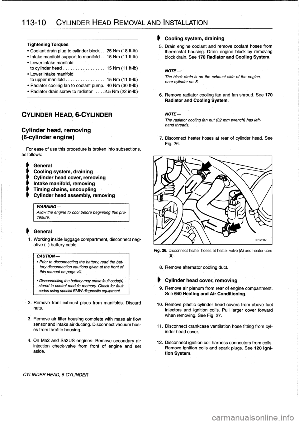
7
.
Disconnect
heater
hoses
at
rear
of
cylinder
head
.
See
Fig
.
26
.
'i
8
.
Remove
alternator
cooling
duct
.
Cylinder
head
cover,
removing
0012687
Fig
.
26
.
Disconnect
heater
hoses
at
heater
valve
(A)
and
heater
core
(B)
.
9
.
Remove
air
plenum
from
rear
of
engine
compartment
.
See640
Heating
and
Air
Conditioning
.
10
.
Remove
plastic
cylinder
head
covers
from
above
fuel
injectors
and
ignition
coils
.
Pull
larger
cover
forward
when
removing
.
See
Fig
.
27
.
11
.
Disconnect
crankcase
ventílation
hose
fitting
from
cyl-
inder
head
cover
.
12
.
Disconnect
ignition
coil
harness
connectors
from
coiis
.
Remove
ignition
coiis
and
spark
plugs
.
See
120
Igni-
tion
System
.
Page 78 of 759
113-12
CYLINDER
HEAD
REMOVAL
AND
INSTALLATION
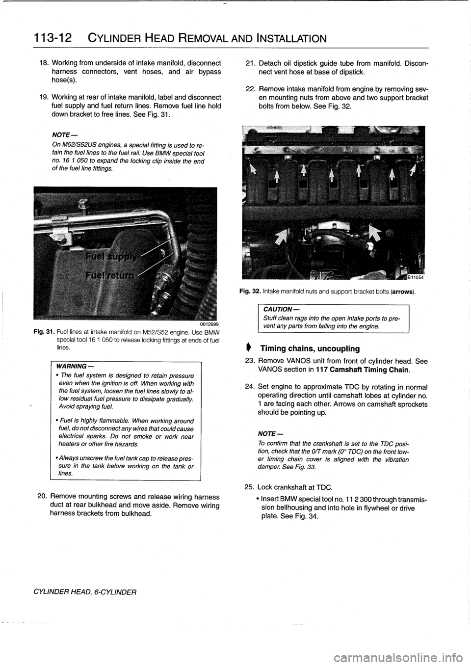
18
.
Working
from
underside
of
intake
manifold,
disconnect
21
.
Detach
oil
dipstick
guide
tube
from
manifold
.
Disconharness
connectors,
vent
hoses,
and
air
bypass
nectvent
hose
at
base
of
dipstick
.
hoses)
.
22
.
Remove
intake
manifold
from
engine
byremoving
sev-19
.
Working
at
rear
of
intake
manifold,
label
and
disconnect
en
mounting
nuts
from
above
andtwo
support
bracket
fuel
supply
and
fuel
return
lines
.
Remove
fuelline
hold
bolts
from
below
.
See
Fig
.
32
.
down
bracket
to
free
lines
.
See
Fig
.
31
.
NOTE-
On
M52IS52US
engines,
a
special
fitting
is
used
to
re-tain
the
fuel
fines
to
the
fuel
rail
.
Use
BMW
special
tool
no
.
16
1
050
to
expand
the
locking
clip
inside
the
end
of
the
fuellíne
fittings
.
WARNING
-
"
The
fuel
system
is
desígned
to
retan
pressure
even
wheh
the
ignition
is
off
.
When
working
with
the
fuel
system,
loosen
the
fuel
lines
slowly
toal-
low
residual
fuel
pressure
to
dissipate
gradually
.
Avoid
spraying
fuel
.
"
Fuel
is
highly
flammable
.
When
working
around
fuel,
do
not
disconnect
any
wires
that
could
cause
electrfcal
sparks
.
Do
not
smoke
orwork
near
heaters
or
other
fire
hazards
.
"
Always
unscrew
the
fuel
tank
cap
to
release
pres-
sure
in
the
tank
before
working
on
the
tank
or
lines
.
20
.
Remove
mountingscrews
and
release
wiring
harness
duct
at
rear
bulkhead
and
move
aside
.
Remove
wiring
harness
brackets
frombulkhead
.
CYLINDER
HEAD,
6-CYLINDER
Fig
.
32
.
Intake
manifoldnuts
and
support
bracket
bolts
(arrows)
.
CAUTION-
Stuff
clean
rags
into
the
open
intake
ports
topre-
001269s
vent
any
ports
from
falfing
into
the
engine
.
Fig
.
31
.
Fuel
lines
at
intake
manifold
on
M52/S52
engine
.
Use
BMW
special
tool
16
1
050
to
release
locking
fittings
at
ends
of
fuel
enes
.
1
Timing
chains,
uncoupling
23
.
Remove
VANOS
unit
from
frontof
cylinder
head
.
See
VANOS
section
in
117
Camshaft
Timing
Chain
.
24
.
Setengine
to
approximate
TDC
by
rotating
in
normal
operating
direction
until
camshaft
lobes
at
cylinder
no
.
1
are
facing
each
other
.
Arrows
on
camshaft
sprockets
should
be
pointing
up
.
NOTE-
To
confirm
that
the
crankshaft
is
set
to
the
TDC
posi-
tion,
check
that
the
OIT
mark
(0°
TDC)on
the
front
low-
er
timing
chain
cover
ís
aligned
with
the
víbration
damperSee
Fig
.
33
.
25
.
Lock
crankshaft
at
TDC
.
"
Insert
BMW
special
tool
no
.
11
2
300
through
transmis-
sion
bellhousing
and
finto
hole
in
flywheelor
drive
plate
.
See
Fig
.
34
.
Page 152 of 759
130-
6
FUEL
INJECTION
Warnings
and
Cautions
For
personal
safety,
as
well
as
the
protection
of
sensitive
electronic
components,
the
following
warnings
and
cautions
should
be
adhered
to
when
working
on
the
engine
manage-
ment
system
.
GENERAL
WARNING
-
"
The
ignition
system
produces
high
voltages
that
can
be
fatal
.
Avoid
contact
with
exposed
termi-
nals
.
Use
extreme
caution
when
working
onacar
with
the
ignition
switched
on
or
the
engine
run-
ning
.
"
Do
not
touch
or
disconnect
any
high
voltage
ca-
bles
from
the
coils
or
spark
plugs
while
the
engine
is
running
or
beingcranked
by
the
starter
.
"
Connect
and
disconnect
the
DME
system
wiring
and
test
equipment
leads
only
when
the
ignition
is
switched
off
.
"
Gasoline
is
highly
flammable
and
fts
vaporsare
explosive
.
Do
not
smoke
or
work
on
a
car
near
heaters
or
other
fire
hazards
when
diagnosing
and
repalring
fuel
system
problems
.
Have
a
tire
extinguisher
avaílable
in
case
of
an
emergency
.
"
When
working
onan
open
fuel
system,
wear
suit-
able
hand
protection,
asprolonged
contact
wfth
fuel
can
cause
illnesses
and
skin
disorders
.
"
Renew
fuel
system
hoses,
clamps
and
O-rings
any
timethey
are
removed
.
"
Before
makingany
electrical
tests
that
require
the
engine
to
be
cranked
using
the
starter,
disable
the
ignition
system
as
described
in
120
Ignition
System
.
CAUTION-
"
Prior
to
disconnecting
the
battery,
read
the
bat-
tery
disconnectinn
cautions
given
at
the
front
of
this
manual
onpage
vifi
.
"
Do
not
connect
any
test
equipment
that
delivers
a
12-volt
power
supply
to
terminal
15
(+)
of
the
ig-
nitioncoil
.
The
current
flow
may
damage
the
ECM
.
In
general,
connect
test
equipment
only
as
speclfied
by
BMW,
this
manual,
or
the
equipment
maker
.
"
Only
use
a
digital
multlmeter
for
electrical
test
.
"
Only
use
an
LED
test
light
for
quick
tests
.
"
Disconnecting
the
battery
may
erase
fault
code(s)
stored
in
memory
.
Check
for
fault
codes
prior
to
disconnecting
the
battery
cables
.
ff
the
Check
Engine
light
ís
illuminated,
see100En-
gine-General
for
DME
fault
code
information
.
ff
any
other
system
faults
have
been
detected
(indi-
catedbyan
illuminated
warning
light),
see
an
au-
thorized
BMW
dealer
.
Additional
systems
with
self-diagnostic
capabilities
include,
ABS
(Anti-
lock
brakes),
SRS
(Airbags),
EML
and
ASC+T
and
AST
(Traction
Control)
.
"
Do
not
run
the
engine
wfth
any
of
the
spark
plug
wires
dlsconnected
.
Catalytic
converter
damage
may
result
.
"
Always
waitat
least
40
seconds
afterturning
off
the
ignition
before
removing
the
engine
control
module
(ECM)
connector
.
ff
the
connector
isre-
moved
before
this
time,
residual
power
in
the
sys-
tem
relay
may
damage
the
control
module
.
"
Cleanliness
is
essential
when
working
onan
open
fuel
system
.
Thoroughly
clean
fuel
line
con-
nections
and
surroundlng
areas
before
loosen-
ing
.
Avoid
moving
the
car
.
Only
fnstall
cleanparts
.
"
Fuel
system
cleaners
and
other
chemical
addi-
tives
other
than
those
specifically
recommended
by
BMW
may
damage
the
catalytic
converter,
the
oxygensensor
or
other
fuel
supply
components
.
Page 154 of 759
130-
8
FUEL
INJECTION
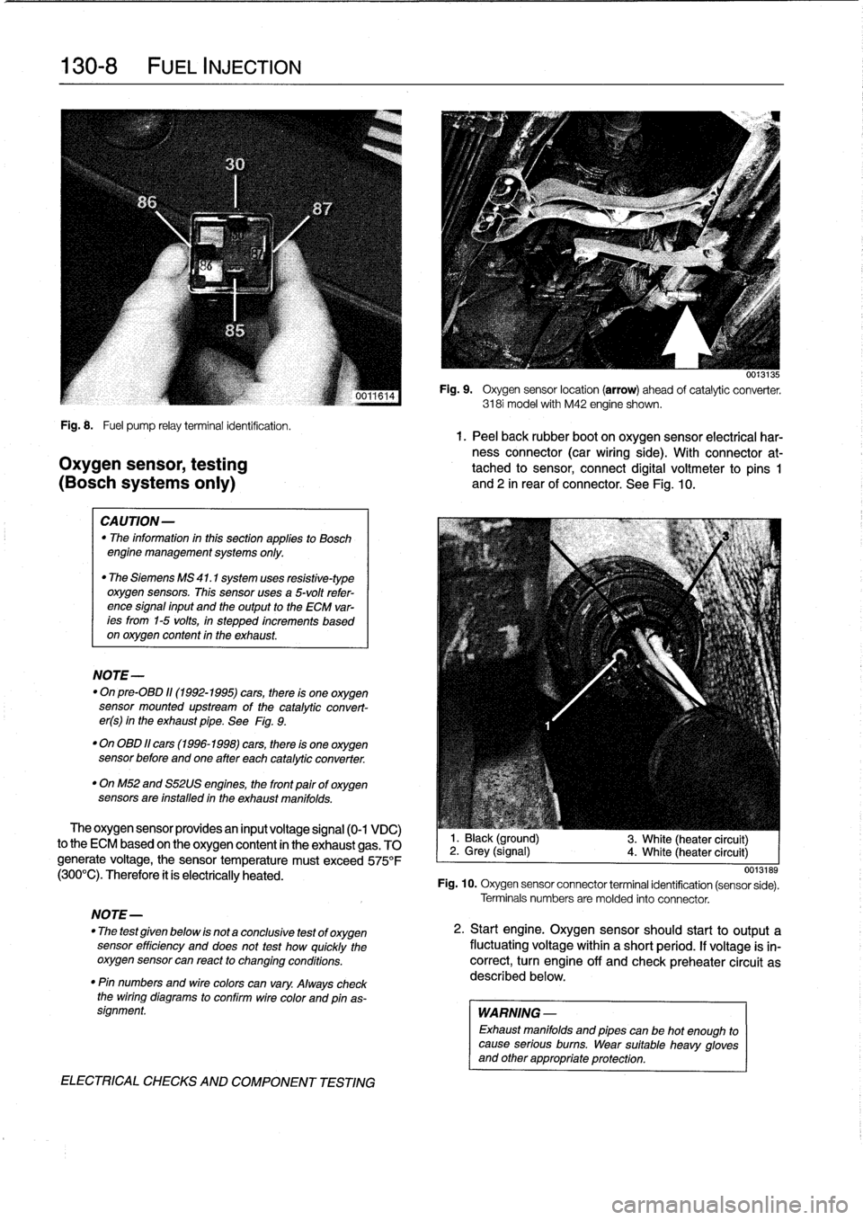
Fig
.
8
.
Fuel
pump
relayterminal
identification
.
1.
Peel
back
rubber
boot
on
oxygen
sensor
electrical
har-
ness
connector
(car
wiring
side)
.
With
connector
at-
Oxygen
sensor,
testing
tached
to
sensor,
connect
digital
voltmeter
to
pins
1
(BOSch
systems
only)
and
2
in
rear
of
connector
.
See
Fig
.
10
.
CAUTION-
"
The
information
inthis
sectionapplies
to
Bosch
engine
management
systems
only
.
"
The
Siemens
MS
41
.1
system
uses
resistive-type
oxygen
sensors
.
This
sensor
uses
a
5-volt
refer-
ence
signal
input
and
the
output
to
the
ECM
var-
ees
from
1-5
volts,
in
stepped
increments
based
on
oxygen
content
in
the
exhaust
.
NOTE-
"
On
pre-08D
11(1992-1995)
cars,
there
is
one
oxygen
sensor
mounted
upstream
of
the
catalytic
convert-
er(s)
in
the
exhaust
pipe
.
See
Fig
.
9
.
"
On
OBD
11
cars
(1996-1998)
cars,
there
is
one
oxygen
sensor
before
andone
after
each
catalytic
converter
.
"
OnM52
and
S52US
engines,
the
front
pairof
oxygen
sensors
are
installed
in
the
exhaust
manifolds
.
The
oxygen
sensor
providesan
input
voltage
signal
(0-1
VDC)
to
the
ECM
based
on
the
oxygen
content
in
the
exhaust
gas
.
TO
generate
voltage,
the
sensor
temperature
must
exceed
575°F
(300°C)
.
Therefore
it
ís
electrically
heated
.
NOTE-
"
The
test
given
below
is
not
a
conclusive
test
of
oxygen
sensor
efficiency
and
does
not
test
how
quickly
the
oxygensensor
can
react
to
changing
conditions
.
"
Pin
numbers
and
wirecolors
can
vary
.
Always
check
the
wiring
diagrams
to
conflrm
wire
color
and
pinas-
signment
.
ELECTRICAL
CHECKS
AND
COMPONENT
TESTING
0013135
Fig
.
9
.
Oxygen
sensor
location
(arrow)
ahead
of
catalytic
converter
.
3181
model
with
M42
engine
shown
.
1
.
Black
(ground)
2
.
Grey
(signal)
4
.
White
(heater
circuit)
3
.
White
(heater
circuit)
0013189
Fig
.
10
.
Oxygen
sensor
connector
terminal
identification
(sensor
sede)
.
Terminals
numbers
are
molded
into
connector
.
2
.
Start
engine
.
Oxygen
sensorshould
start
to
output
a
fluctuating
voltage
within
a
short
period
.
If
voltage
is
in-
correct,
turn
engine
off
and
check
preheater
circuit
as
described
below
.
WARNING
-
Exhaust
manifolds
and
pipes
can
be
hot
enough
to
cause
serious
burns
.
Wear
suitable
heavy
gloves
and
other
appropriate
protection
.
Page 155 of 759
Oxygen
Sensor
FUEL
DELIVERY
TESTS
FUEL
INJECTION
130-
9
"
Voltage
at
¡dle
..
.
..
..
....
0
.2
to
0
.8
VDC,
fluctuating
Checking
fuel
delivery
is
afundamental
part
of
trouble-
shooting
and
diagnosing
the
engine
management
system
.
Fuel
pressure
directly
influences
fuel
delivery
.
An
accurate
NOTE-
fuel
pressure
gauge
will
be
needed
to
make
the
tests
.
To
check
sensorresponse
to
lean
and
rich
mixtures,
createenairleak,
orpull
vacuumhoseofffue¡
pressure
There
are
three
significant
fuel
delivery
values
to
be
mea-
regulator
to
increase
fuel
pressure
.
sured
:
3
.
Separate
sensorharness
connector
from
sensor
.
Check
for
battery
voltage
between
terminals
3
and
4
(green
wire
and
brown
wire)
in
main
wiring
harness
side
of
con-
nector
with
engine
running
.
If
voltage
is
not
present,
check
oxygen
sensor
heater
relay
.
See610
Electrical
Component
Locations
.
4
.
Check
heater
element
resistance
between
terminals
3
and
4
in
sensor
side
of
connector
.
If
element
is
electri-
cally
open
(no
continuity),
replace
sensor
.
NOTE-
The
oxygen
sensor
heater
relay
is
mounted
in
the
main
power
distributfon
box
in
the
left
rear
of
the
engine
com-
partment
.
Refer
to
Fig
.
6
.
The
heater
relay
is
energized
wíth
positive
(+)
battery
voltage
from
the
main
relayanda
switched
ground
from
the
ECM
.
See
Electrical
Wir-
ing
Diagrams
.
"
Oxygen
sensor
to
exhaust
pipe
...
..
55
Nm
(41
ft-Ib)
"
System
pressure-created
by
the
fuel
pump
and
main-
tained
by
the
pressure
regulator
.
"
Fuel
delivery
volume-created
by
the
fuel
pump
and
af-
fected
by
restrictions,
suchasclogged
fuel
filter
.
"
Residual
pressure-the
pressure
maintained
in
the
closed
system
after
the
engine
and
fuel
pump
are
shut
off
.
Procedures
for
measuring
the
first
two
quantities
arede-
scribed
in
160
Fuel
Tank
and
Fuel
Pump
.
Residual
fuel
pres-
sure
is
checked
using
the
procedure
detailed
later
in
this
group
.
Operating
fuel
pump
fortests
To
operate
the
fuel
pump
for
testing
purposes
without
hav-
íng
to
runthe
engine,
the
fuel
pump
relay
can
be
bypassed
to
power
the
pump
directly
.
Fuel
pump
relay
location
is
shown
in
Fig
.
6
.
5
.
¡f
oxygen
sensor
doesn't
produce
a
fluctuating
voltage
To
runthe
fuel
pump,
remove
the
fuel
pump
relay
and
con-
and
preheater
circuit
is
OK,
replace
sensor
.
nect
the
socket
for
relayterminal
30
to
the
socket
for
relay
ter-
mina¡
87
with
a
fused
jumper
wire
.
After
completing
the
tests,
NOTE-
remove
the
jumper
wire
.
If
not
already
applied,
coat
the
oxygen
sensor
threads
with
an
anti-seize
compound
before
installation
.
Do
not
CAUTION-
getthe
compound
on
the
sensor
tip
.
"
Relay
locations
may
vary
.
Use
care
when
identi-
fying
relays
and
making
electrical
checks
at
the
fuselrelay
panel
.
See
610
Electrical
Compo
Tightening
Torque
nent
Locations
for
additional
relay
information
.
"
The
fuel
pump
relay
has
a
1
.5
mm2
red
wire
at
ter-
minal
30
in
the
relay
socket
.
Terminal
87
has
a
1
.5
mm
2
greenlviolet
wire
.
See
Electrical
Wiring
Di-
agrams
for
additional
wiring
information
.
NOTE-
Thejumper
wire
should
be
1.5
mm2
(14
ga
.)
and
in-
clude
an
in-line
tuse
holder
with
a15
amp
tuse
.
To
avoid
fuselrelay
panel
damage
from
repeated
connect-
ing
and
disconnecting,
also
include
a
toggle
switch
.
A
heavy-duty
jumper,
BMW
tool
no
.
61
3
050,
is
also
available
from
an
authorized
BMW
dealer
.
FUEL
DELIVERYTESTS
Page 156 of 759
130-
1
0
FUEL
INJECTION
Relleving
fuel
pressure
and
connecting
fuel
pressure
gauge
WARNING
-
"
Gasoline
is
highly
flammable
and
its
vaporsare
explosive
.
Do
not
smoke
orwork
on
acarnear
heaters
or
other
fire
hazards
when
diagnosing
and
repairing
fuel
system
problems
.
Have
a
fire
extinguisher
available
in
case
of
an
emergency
.
"
When
working
onanopen
fuel
system,
wear
suit-
able
hand
protection
.
Prolonged
contact
with
fuel
can
cause
illnesses
and
skin
disorders
.
To
prevent
fuel
from
spraying
on
a
hot
engine,
system
fuel
pressure
should
be
relieved
before
disconnecting
fuel
lines
.
One
method
is
to
tightly
wrap
a
shop
towel
around
a
fuelline
fit-
ting
and
loosenor
disconnect
the
fitting
.
Cleanliness
is
essential
when
working
with
fuelcircuit
com-
ponents
.
Thoroughly
clean
theunionsbefore
disconnecting
fuellines
.
NOTE-
"
OnM44
engines,
a
Schrmder
valve
is
integrated
in
the
fuel
rail
.
Compressed
air
pressure
canbe
applied
at
the
valve
to
force
the
fuel
in
the
system
back
into
the
tank
.
See
Fig
.
11
.
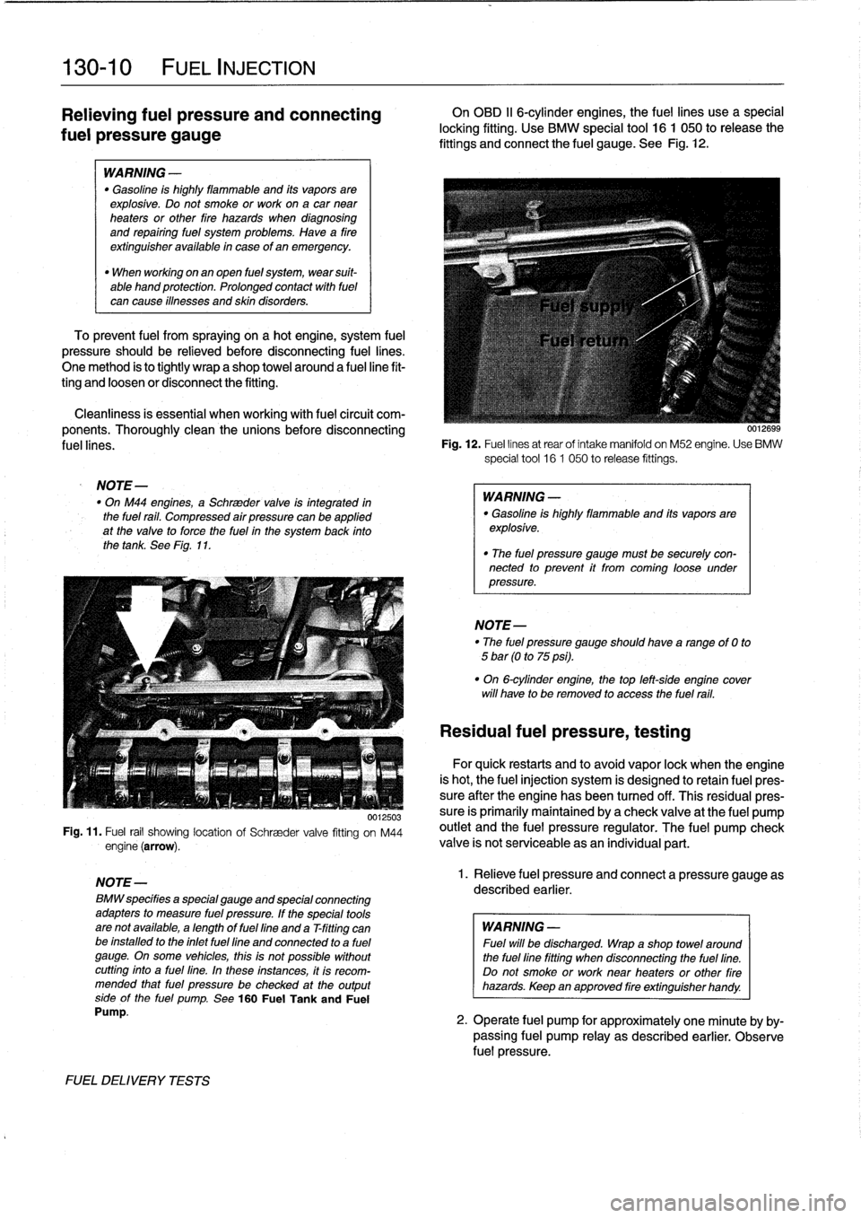
0012503
Fig
.
11
.
Fuel
rail
showing
location
of
Schraeder
valve
fitting
on
M44
engine
(arrow)
.
NOTE-
B~
specifies
a
special
gauge
and
special
connecting
adapters
to
measure
fuel
pressure
.
If
the
special
tools
arenot
available,
a
length
of
fuel
fine
and
a
T-fitting
canbe
installed
to
the
inlet
fuel
fine
and
connected
to
a
fuel
gauge
.
On
some
vehicles,
thisis
not
possible
without
cutting
finto
a
fuel
lino
.
In
these
lnstances,
it
Is
recom-
mended
that
fuel
pressure
be
checked
at
theoutput
sidoof
the
fuel
pump
.
See
160
Fuel
Tankand
Fuel
Pump
.
FUELDELIVERY
TESTS
On
OBD
II
6-cylinder
engines,
the
fuel
lines
use
a
special
locking
fitting
.
Use
BMW
special
tool
16
1
050
to
release
the
fittings
and
connect
the
fuel
gauge
.
See
Fig
.
12
.
0012699
Fig
.
12
.
Fuel
linos
at
rear
of
intake
manifold
on
M52
engine
.
Use
BMW
special
tool
16
1
050
torelease
fittings
.
WARNING
-
"
Gasoline
is
highly
flammable
and
its
vapors
are
explosive
.
"
The
fuel
pressure
gauge
must
be
securely
con-nected
to
prevent
it
from
coming
loose
under
pressure
.
NOTE-
"
The
fuel
pressure
gauge
should
have
arangoof
0
to
5
bar
(0
to
75
psi)
.
"
On
6-cylinder
engine,
thetop
left-sido
engine
cover
will
have
to
be
removed
to
access
the
fuel
rail
.
Residual
fuel
pressure,
testing
For
quick
restarts
and
to
avoid
vapor
lock
when
the
engine
is
hot,
the
fuel
injection
system
is
designed
to
retain
fuel
pres-
sure
after
the
engine
has
been
turned
off
.
Thís
residualpres-
sure
is
primarily
maíntained
by
a
check
valve
at
the
fuel
pump
outiet
and
the
fuel
pressure
regulator
.
The
fuel
pump
check
valve
is
not
serviceable
asan
individual
part
.
1.
Relieve
fuel
pressure
and
connect
a
pressure
gauge
as
described
earlier
.
WARNING
-
Fuel
will
be
discharged
.
Wrap
a
shop
towel
around
the
fuellino
fitting
when
disconnecting
the
fuel
fine
.
Do
not
smoke
or
worknear
heaters
or
other
fire
hazards
.
Keep
an
approved
fire
extinguisher
handy
.
2
.
Operate
fuel
pump
for
approximately
one
minuto
by
by-
passing
fuel
pump
relay
as
described
earlier
.
Observe
fuel
pressure
.
Page 158 of 759
130-
1
2
FUEL
INJECTION
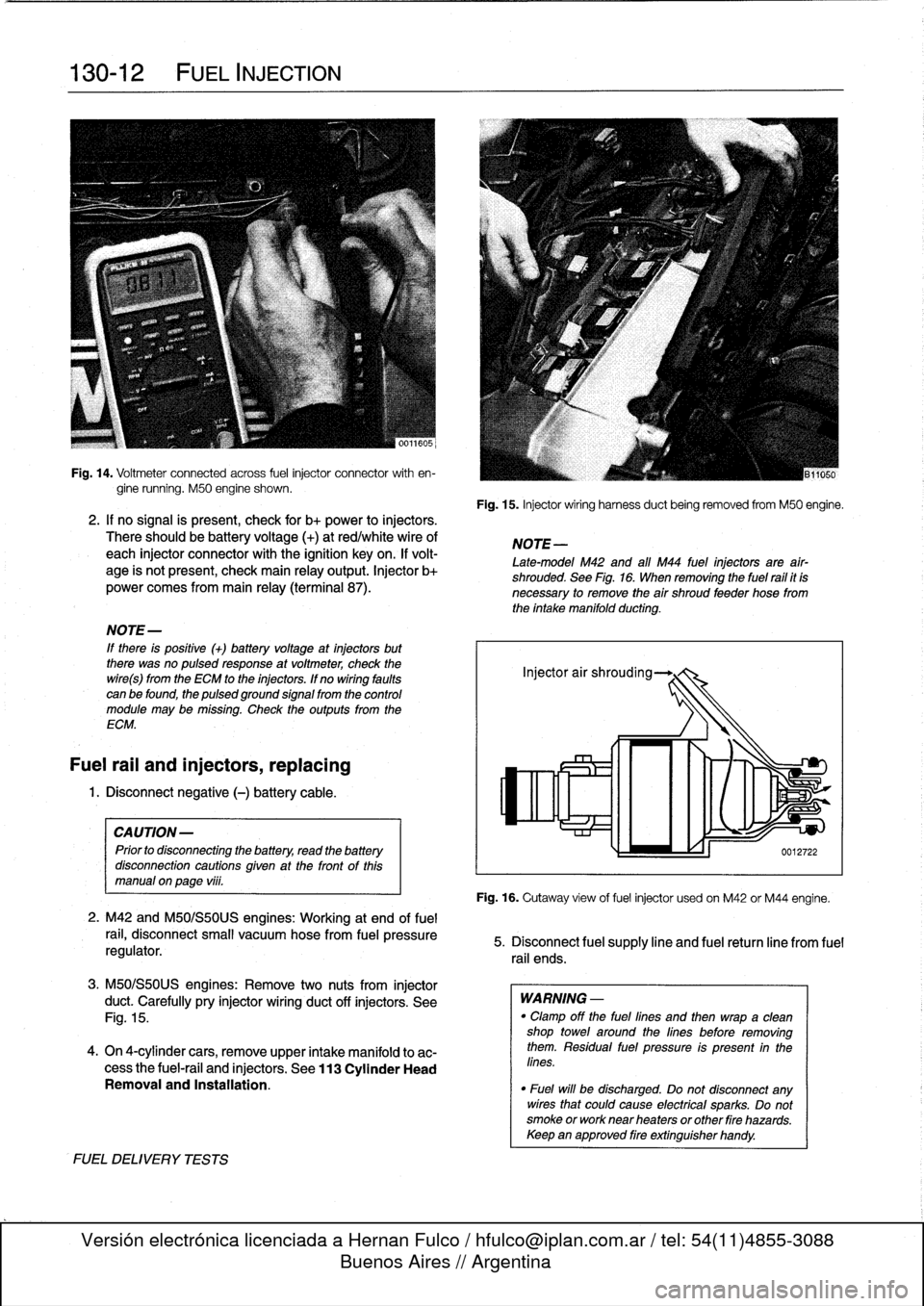
Fig
.
14
.
Voitmeter
connected
across
fuel
injector
connector
with
en-
gine
running
.
M50
engine
shown
.
2
.
If
no
signal
is
present,
check
for
b+
power
to
injectors
.
There
should
be
battery
voltage
(+)
at
red/whitewire
of
each
injector
connector
with
the
ignition
key
on
.
If
volt-
age
is
not
present,
check
main
relay
output
.
Injector
b+
power
comes
from
main
relay
(terminal
87)
.
NOTE-
If
there
is
positive
(+)
batteryvoltage
at
injectors
but
there
was
no
pulsedresponse
at
voltmeter,
check
the
wire(s)
from
the
ECM
to
the
injectors
.
If
no
wiring
faults
can
be
found,
the
pulsed
ground
signal
from
the
control
module
may
be
missing
.
Check
the
outputs
from
the
ECM
.
Fuel
rail
and
injectors,
replacing
1
.
Disconnect
negative
(-)
battery
cable
.
CAUTION-
Prior
to
disconnectiog
the
battery,
read
the
battery
disconnection
cautions
given
at
the
tront
of
this
manual
on
page
viii
.
2
.
M42
and
M50/S50US
engines
:
Working
at
end
offuel
rail,
disconnect
small
vacuum
hose
from
fuel
pressure
regulator
.
3
.
M50/S50US
engines
:
Remove
two
nuts
from
injector
duct
.
Carefully
pry
injector
wiring
duct
off
ínjectors
.
See
Fig
.
15
.
4
.
On
4-cylinder
cars,
remove
upper
intake
manifold
to
ac-
cess
the
fuel-rail
and
injectors
.
See
113
Cylinder
Head
Removal
and
Installation
.
FUELDELIVERYTESTS
Fig
.
15
.
Injector
wiring
harness
duct
being
removed
from
M50
engine
.
NOTE
-
Late-model
M42
and
all
M44
fuel
injectors
are
afr-
shrouded
.
See
Fig
.
16
.
When
removing
the
fuel
rail
it
is
necessary
to
remove
the
air
shroud
feeder
hose
from
the
intake
manifold
ducting
.
Fig
.
16
.
Cutaway
view
of
fuelinjector
usedon
M42
or
M44
engine
.
5
.
Disconnect
fuel
supply
line
and
fuel
retum
line
from
fuel
rail
ends
.
WARNING
-
"
Clamp
off
the
fuel
lines
and
then
wrapa
clean
shop
towei
around
the
lines
before
removing
them
.
Residual
fuel
pressure
is
present
in
the
lines
.
"
Fuel
will
be
discharged
.
Do
not
disconnect
any
wires
that
could
cause
electrical
sparks
.
Do
not
smoke
or
worknear
heaters
or
other
fire
hazards
.
Keepan
approved
fire
extinguisher
handy
.
Page 159 of 759
6
.
Remove
fuel
rail
mounting
bolts
.
See
Fig
.
17
.
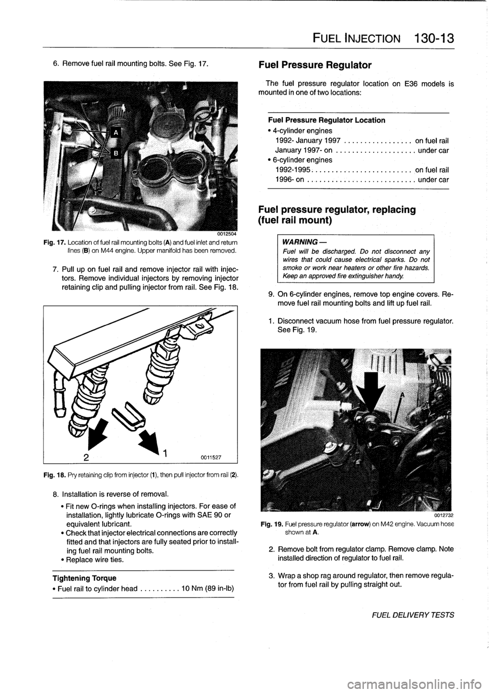
0012504
Fig
.
17
.
Location
of
fuel
rail
mounting
bolts
(A)
and
fuel
inlet
and
return
lines
(B)
on
M44
engine
.
Upper
manifold
has
been
removed
.
7
.
Pull
upon
fuel
rail
and
remove
injector
rail
with
injec-tors
.
Remove
individualinjectors
by
removing
injector
retaining
clip
and
pullinginjector
from
rail
.
See
Fig
.
18
.
Fig
.
18
.
Pry
retaining
clip
from
injector
(1),
then
pull
injector
from
rail
(2)
.
8
.
Installation
is
reverse
of
removal
.
Tightening
Torque
"
Fuel
rail
to
cylinder
head
..
.
..
..
...
10
Nm
(89
in-lb)
FUEL
INJECTION
130-
1
3
Fuel
Pressure
Regulator
The
fuel
pressure
regulator
location
on
E36
models
is
mounted
in
one
of
two
locations
:
Fuel
Pressure
Regulator
Location
"
4-cylinder
engines
1992-
January
1997
............
...
..
on
fuel
rail
January
1997-
on
...............
..
...
under
car
"
6-cylinderengines
1992-1995
.
.
...
...
.
...........
...
..
on
fuel
rail
1996-on
..
.
..
................
...
...
undercar
Fuel
pressure
regulator,
replacing
(fuel
rail
mount)
WARNING
-
Fuel
will
be
discharged
.
Do
not
disconnect
any
wires
that
could
cause
electrícal
sparks
.
Do
not
smoke
or
work
near
heaters
or
other
fire
hazards
.
Keepan
approved
fire
extinguisher
handy
.
9
.
On
6-cylinder
engines,
remove
top
engine
covers
.
Re-
move
fuel
rail
mounting
bolts
and
lift
up
fuel
rail
.
1
.
Disconnect
vacuum
hose
from
fuel
pressure
regulator
.
See
Fig
.
19
.
"
Fit
new
O-rings
when
installing
injectors
.
For
ease
of
installation,
lightly
lubricate
O-rings
with
SAE
90
or
0012732
equivalent
lubricant
.
Fig
.
19
.
Fuel
pressure
regulator
(arrow)
on
M42
engine
.
Vacuum
hose
"
Check
that
injector
electrical
connections
are
correctly
shown
at
A
.
fitted
and
that
injectors
are
fully
seated
prior
to
install-
ing
fuel
rail
mounting
bolts
.
2
.
Remove
bolt
from
regulator
clamp
.
Remove
clamp
.
Note
"
Replace
wire
ties
.
installed
direction
of
regulator
to
fuel
rail
.
3
.
Wrap
a
shop
rag
around
regulator,
then
remove
regula-
tor
from
fuel
rail
by
pulling
straight
out
.
FUELDELIVERYTESTS
Page 160 of 759
130-
1
4
FUEL
INJECTION
NOTE-
Be
sure
to
retrieve
thrust
washer
behind
fuel
pressure
regulator
on
6-cylinder
engine
.
4
.
Installation
is
reverse
of
removal
.
Replace
O-rings
.
Fuel
pressure
regulator,
replacing
(under
car
mount)
WARNING
-
Fuel
will
be
discharged
.
Do
not
disconnect
any
wires
that
could
cause
electrical
sparks
.
Do
not
smoke
or
work
near
heaters
or
other
fire
hazards
.
Keep
an
approved
tire
extinguisher
handy
.
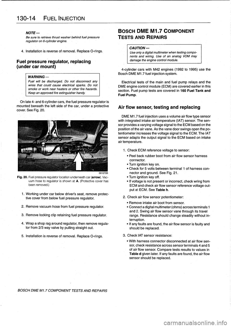
On
late
4-
and
6-cylinder
cars,
the
fuel
pressure
regulator
is
mounted
beneath
the
left
sideof
the
car,
under
a
protective
cover
.
See
Fig
.
20
.
0012726
Fig
.
20
.
Fuel
pressure
regulatorlocation
underneath
car
(arrow)
.
Vac-
uum
hose
to
regulator
is
shown
at
A
.
(Protective
cover
has
been
removed
.)
5
.
Installation
is
reverse
of
removal
.
Replace
O-rings
.
BOSCH
DME
Ml
.
7
COMPONENT
TESTS
AND
REPAIRS
BOSCH
DME
Ml
.7
COMPONENT
TESTS
AND
REPAIRS
CA
UTION-
Use
only
a
digital
multimeter
when
testing
compo-
nents
and
wiring
.
Use
of
an
analog
VOM
may
damage
the
engine
control
module
.
4-cylinder
cars
with
M42
engines(1992
to
1995)use
the
Bosch
DME
M1
.7
fuel
injection
system
.
Electrical
tests
of
the
main
and
fuel
pump
relays
and
the
DME
engine
control
module
(ECM)
are
covered
earlier
in
this
section
.
Fuel
pump
tests
arecovered
in
160
Fuel
Tank
and
Fuel
Pump
.
Air
flow
sensor,
testing
and
replacing
DME
M1
.7
fuel
injection
uses
a
volume
air
flow
type
sensor
with
integrated
intake
air
temperature
(IAT)
sensor
.
The
sen-
sor
provides
a
varyingvoltage
signal
to
the
ECM
based
on
the
position
of
the
air
vane
.
As
the
vane
doorswings
open
thepo-
tentiometer
increases
the
voltage
signal
to
the
ECM
.
The
IATsensor
adapts
theoutput
signal
to
the
ECM
based
on
intake
air
temperature
.
1
.
Check
ECM
reference
voltage
to
sensor
:
"
Peel
back
rubber
boot
from
air
flow
sensor
harness
connector
.
"
Turn
ignition
keyon
.
"
Check
for
5
volts
between
terminal
1
of
harness
con-
nector
and
ground
.
See
Fig
.
21
.
"
Turn
ignition
key
off
.
"
If
voltage
is
not
present
or
incorrect,
check
wring
from
ECM
and
check
air
flow
sensor
reference
voltage
out-
put
at
ECM
.
See
Table
h
.
1
.
Working
under
car
below
driver's
seat,
remove
protec-
tive
cover
from
below
fuel
pressure
regulator
.
"
Remove
intake
air
bootfrom
sensor
.
2
.
Remove
vacuum
hosefrom
fuel
pressure
regulator
.
"
Connect
a
digital
multimeter
(ohms)
across
terminais
1
and
2
.
Swing
air
flow
sensor
vane
through
its
travel
3
.
Remove
locking
clip
retaining
fuel
pressure
regulator
.
range
.
Resistance
should
change
steadily
without
in-
terruption
.
4
.
Wrap
a
shop
rag
around
regulator,
then
remove
regula-
"
If
any
faults
are
found,
the
air
flow
sensor
is
faulty
and
tor
from
213
way
valve
by
pullingstraight
out
.
should
be
replaced
.
2
.
Check
air
flow
sensor
potentiometer
:
3
.
Check
IAT
sensor
resistance
:
"
With
harness
connector
disconnected
at
air
flow
sen-
sor,
check
resistance
across
sensor
terminais
4
and
5
of
air
flow
sensor
.
Compare
tests
results
to
values
in
Table
d
given
later
.
If
any
faults
are
found,
the
air
flow
sensor
should
be
replaced
.
Page 174 of 759
130-
2
8
FUEL
INJECTION
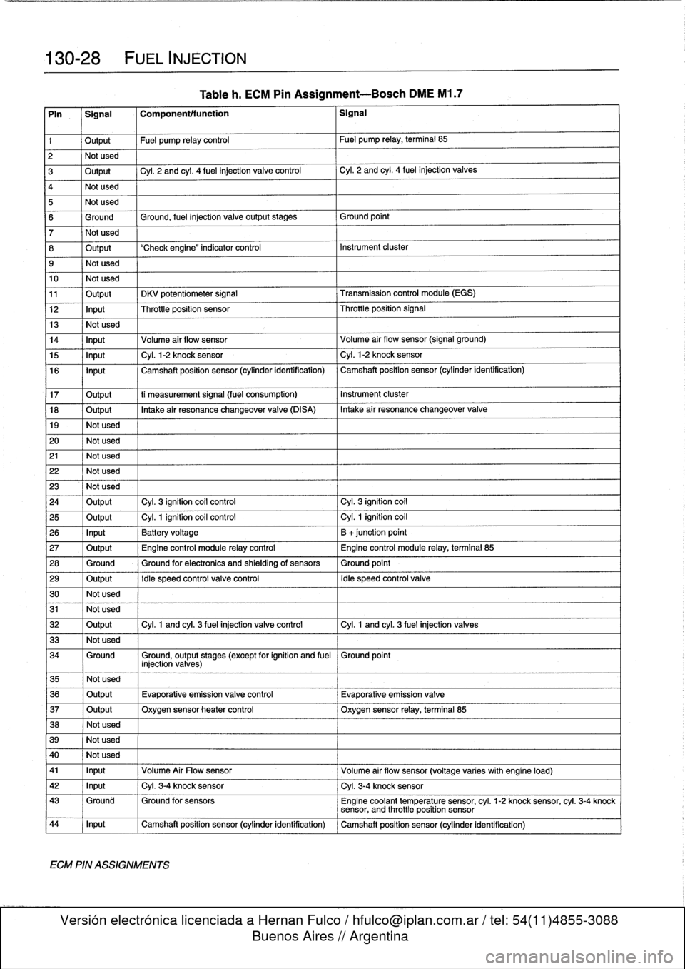
Tableh
.
ECM
Pin
Assignment-Bosch
DME
M1
.7
Pin
Signal
Componenttfunction
Signal
1
Output
Fuel
pump
relay
control
Fuel
pump
relay,
terminal
85
2
Not
used
3
Output
Cyl
.
2
and
cyl
.
4
fuel
injection
valve
control
Cyl
.
2
and
cyl
.
4
fuel
injection
valves
4
Not
used
5
Not
used
6
Ground
Ground,
fuel
injection
valveoutputstages
Ground
point
7
Not
used
8
Output
"Check
engine"
indicator
control
Instrument
cluster
9
Not
used
10
Not
used
11
Output
DKV
potentiometer
signal
Transmission
control
module
(EGS)
12
Input
Throttleposition
sensor
Throttleposition
Signal
13
Not
used
14
Input
Volume
air
flow
sensor
Volume
air
flow
sensor
(signal
ground)
15
Input
Cyl
.
1-2
knock
sensor
Cyl
.
1-2
knock
sensor
16
Input
Camshaft
position
sensor
(cylinder
identification)
Camshaft
position
sensor
(cylinder
identification)
17
Output
ti
measurement
signal
(fuel
consumption)
Instrument
cluster
18
Output
Intakeair
resonance
changeover
valve
(DISA)
Intake
air
resonance
changeover
valve
19
-
Not
used
20
Not
used
21
Not
used
22
Not
used
23
Not
used
24
Output
Cyl
.
3
ignition
coil
control
Cyl
.
3
ignition
coil
25
Output
Cyl
.
1
ignition
coil
control
Cyl
.
1
ignition
coil
26
Input
Battery
voltage
B
+junction
point
27
Output
Engine
control
module
relay
control
Engine
control
module
relay,
terminal
85
28
Ground
Ground
for
electronics
and
shielding
of
sensors
Ground
point
29
Output
Idle
speed
control
valve
control
Idle
speed
control
valve
30
Not
used
31
Not
used
32
Output
Cyl
.
1
and
cyl
.
3
fuel
injection
valve
control
Cyl
.
1
and
cyl
.
3
fuel
injection
valves
33
Not
used
34
Ground
Ground,
output
stages
(except
for
ignition
and
fuel
Ground
point
injection
valves)
35
Not
used
36
Output
Evaporative
emissionvalve
control
Evaporative
emission
valve
37
Output
Oxygen
sensor
heater
control
Oxygen
sensor
relay,
terminal
85
38
Not
used
39
Not
used
40
I
Not
used
41
I
Input
,
Volume
Air
Flow
sensor
Volume
air
flow
sensor
(voltage
varies
with
engine
load)
42
1
Input
1
Cyl
.
3-4
knock
sensor
1
Cyl
.
3-4
knock
sensor
43
Ground
Ground
for
sensors
Engine
coolant
temperature
sensor,
cyl
.
1-2
knock
sensor,
cyl
.
3-4
knock
sensor,
and
throttle
position
sensor
44
1
Input
1
Camshaft
position
sensor
(cylinder
identification)
1
Camshaft
position
sensor
(cylinder
identification)
ECM
PIN
ASSIGNMENTS