engine oil change BMW M3 1993 E36 Owner's Manual
[x] Cancel search | Manufacturer: BMW, Model Year: 1993, Model line: M3, Model: BMW M3 1993 E36Pages: 759
Page 198 of 759
170-
4
RADIATOR
AND
COOLING
SYSTEM
A
quick
testat
the
coolant
temperature
gauge
sender
can
The
auxiliary
cooling
fan
comes
on
when
coolant
tempera
determine
if
the
gauge
is
functioning
correctly
.
ture
exceeds
a
predetermined
leve¡
or
whenever
the
air
condi-
tioning
is
on
.
A
dual-range
temperature
switch
for
cooling
fan
lf
the
gauge
needie
remains
at
the
rest
position
with
theen-
control
is
mounted
on
the
right
side
of
the
radiator
.
See
Fig
.
3
.
gine
warm,
remove
the
harness
connector
from
the
sender
and
jumper
the
correct
terminals
in
the
connector
to
simulate
a
high
engine
temperature
.
See
Table
a
.
Turn
the
ignition
on
.
If
the
gauge
needle
moves
upward,
the
sender
is
faulty
.
If
the
gauge
does
not
respond,
the
wiring
to
the
gauge
is
broken
(open
circuit)
or
the
gauge
itselfis
faulty
.
WARNING
-
1996
and
laten
models
are
OBD
11
compliant
.
Dis-
connecting
electrical
connectors
wíth
the
ignition
turned
on
may
set
fault
codes
in
the
ECM
.
It
is
rec-
ommended
that
you
leave
the
diagnosis
of
faults
in
the
coolant
temperature
sensorsystem
to
the
BMW
dealer
service
department
which
has
specialized
OBD
11
scan
tool
equipment
.
If
the
gauge
needle
reads
too
high
when
the
engine
is
cold,
remove
the
harness
connector
from
the
sender
.
Turn
the
igni-
tion
on
.
lf
the
gauge
needle
position
does
not
change,
the
wir-
ing
or
the
gauge
is
shorted
to
ground
.
If
the
gauge
needle
drops,
the
sender
is
faulty
and
should
be
replaced
.
When
re-
placing
a
faulty
coolant
temperature
sender,
the
gasket
ring
on
the
sender
should
also
be
replaced
.
Tightening
Torque
"
Temperature
gauge
sender
to
engine
18
Nm
(13
ft-Ib)
Cooling
fan,
testing
NOTE-
OnM44
engines
with
manual
transmission,
the
primary
electric
cooling
fan
is
mounted
on
the
engine
side
of
the
radiator
and
is
controlled
by
the
engine
control
module
(ECM)
.
Troubleshooting
thiscircuit
should
be
left
to
an
authorized
BMW
dealer
with
the
proper
diagnostic
equipment
An
otherwise
sound
cooling
system
may
still
overheat,
par-
ticularly
with
prolonged
idling,
due
to
a
failure
of
the
coolíng
fan(s)
.
The
belt-driven
cooling
fan
is
controlled
by
a
temperature
dependent
viscous
clutch
.
A
failed
fan
clutch
may
affect
air
flow
through
the
radiator
resulting
in
overheating
orpossibly
overcooling
.
Speed
Low
sp
High
s
With
the
engine
off,
check
thefan
clutch
by
spinning
thefan
.
eed
The
fan
should
spin
on
the
clutch
with
some
resistance
.
peed
Check
for
signs
of
leaking
fluid
from
the
clutch
.
If
thefan
free-
wheels
with
no
resistance,
cannot
be
tu
rned
by
hand,
or
there
are
signs
of
oil
leakage,
the
clutch
should
be
replaced
.
TROUBLESHOOTING
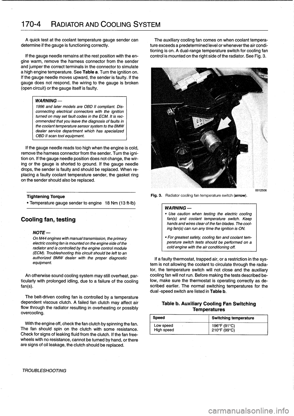
Fig
.
3
.
Radiatorcooling
fan
temperature
switch
(arrow)
.
WARNING
-
"
Use
caution
when
testing
the
electric
cooling
fan(s)
and
coolant
temperature
switch
.
Keep
hands
and
wires
clear
of
thefan
blades
.
The
cool-
ing
fan(s)
can
run
any
time
the
ignition
is
ON
.
"
For
greatest
safety,
coolíng
fan
and
coolant
tem-perature
switch
tests
shouldbe
performed
on
acoldengine
with
the
air
conditioning
off
.
Table
b
.
Auxiliary
Cooling
Fan
Switching
Temperatures
Switching
temperature
196°F(91°C)
210°F(99°C)
0012506
If
a
faulty
thermostat,
trapped
air,
or
a
restriction
in
the
sys-
tem
is
not
allowing
the
coolant
to
circulate
through
the
radia-
tor,
the
temperature
switch
will
not
close
and
the
auxiliary
cooling
fan
will
not
run
.
Before
making
the
tests
described
be-
low,
make
sure
the
thermostat
is
operating
correctly
as
de-
scribed
earlier
.
The
normal
switching
temperatures
for
the
dual
-speed
switch
are
listed
in
Table
b
.
Page 207 of 759
GENERAL
.
.
.......
.
......
.
...
.
.
.
.
.
...
180-1
Exhaust
system,
removing
and
installing
.
...
.180-3
EXHAUST
SYSTEM
REPLACEMENT
.
...
180-1
Exhaust
manifolds,
removing
and
installing
.
.
.180-5
GENERAL
The
exhaust
system
is
designed
to
be
maintenance
free,
al-
though
regular
inspection
is
warranted
due
to
the
harsh
oper-
atingconditions
.
Under
normal
conditions,
the
catalytic
converter
does
not
require
replacement
unless
it
is
damaged
.
On
1996
and
later
cars,
a
pre-
and
post-catalytic
converter
oxygen
sensor
is
used
at
each
catalytic
converter
.
Be
sure
to
take
care
when
removingthe
system
not
to
damage
the
sen-
EXHAUST
SYSTEMREPLACEMENT
sors
.
See
130
Fuel
Injection
for
information
on
testing
oxygen
sensors
.
NOTE-
OnM52
engines,
two
resonator
pípes
(short
and
long)
are
incorporated
into
the
rear
muffler
assembly
.
See
Fíg
.
1
.
An
exhaust
flap
is
integrated
into
the
outlet
side
of
the
short
pipe
.
The
flap
is
operated
by
a
vacuum
ac-
tuator
via
the
Siemens
MS
41
.1
engine
control
mod-
ule)
.
The
flap
is
closed
at
engine
speeds
below
2,500
rpm
.
This
allows
exhaust
gasses
to
flow
through
the
long
resonator
pipe
and
reduce
noise
.
Above
2,500rpm,
the
exhaust
flap
is
open
(no
vacuum
applied
to
the
actuator)
and
allows
exhaust
gasses
to
flow
through
the
short
pipe
for
maximum
performance
.
180
Exhaust
System
0013101
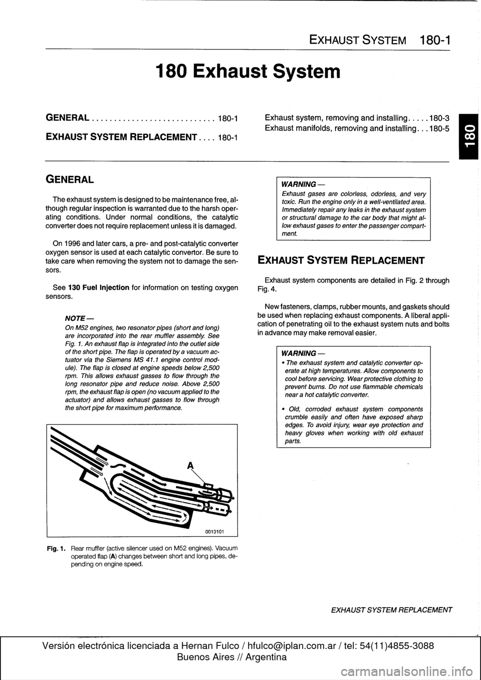
Fig
.
1
.
Rear
muffler
(active
silencer
usedon
M52
engines)
.
Vacuum
operated
flap
(A)
changesbetween
short
and
long
pipes,
de-
pending
on
engine
speed
.
EXHAUST
SYSTEM
180-1
WARNING
-
Exhaust
gases
are
colorless,
odorless,
and
very
toxic
.
Run
the
engine
only
ín
a
well-ventilated
area
.
Immediately
repair
any
leaks
in
the
exhaust
system
or
structural
damage
to
the
car
body
that
might
al-
lowexhaust
gases
to
enter
the
passenger
compart-
ment
.
Exhaustsystem
components
are
detailed
in
Fig
.
2
through
Fig
.
4
.
New
fasteners,
clamps,rubber
mounts,
and
gaskets
should
be
used
when
replacing
exhaust
components
.
A
liberal
appli-
cationof
penetrating
oil
to
the
exhaustsystem
nuts
and
bolts
in
advance
may
make
removal
easier
.
WARNING
-
"
The
exhaust
system
and
catalytic
converter
op-
erate
at
high
temperatures
.
Allow
components
to
cool
before
servicing
.
Wear
protectíve
clothíng
to
prevent
bums
.
Do
not
use
flammable
chemicals
near
a
hot
catalytic
converter
.
"
Old,
corroded
exhaust
system
components
crumble
easíly
and
often
have
exposed
sharp
edges
.
To
avoid
injury,
wear
eye
protection
and
heavy
gloves
when
working
with
old
exhaust
parts
.
EXHAUST
SYSTEM
REPLACEMENT
T
Page 401 of 759
Component
Model
Year
Location
Refer
to
Heater
Recirculation
Flap
Actuator
1992-1998
Below
left
dash
right
side
of
steering
column
HeaterBlowerMotor
Resistor
Pack
1992-1998
Behind
center
of
dashboard
Heater
Regulator
FlapActuator
1997-1998
Right
side
of
heater
box
HeaterValve
Assembly
1992-1998
Left
rear
engine
compartment
HeatingNentilation
Relay
Box
1992-1993
Below
left
side
of
dash
HeatingNentilation
Relay
1994-1998
Left
front
footwell
High
Speed
Cooling
Fan
Relay
1992-1998
Power
distribution
box
Fig
.
2
.
Homs,
Right/Left
1993-1998
Front
of
engine
compartment
Horn
Relay
1992-1998
Power
distribution
box
Fig
.
2
.
Horn
Relay
(Alpine)
1994-1998
Behind
glove
compartment
Fig
.
8
.
Board
Computer/Anti-Theft
Fig
.
9
.
Idle
Speed
Control
Valve
1992-1995
Top
rearof
enginebehind
intake
manifold
(M42
engine)
Fig
.
11
.
Idle
Speed
Control
Valve
1992-1995
Top
left
side
of
engine
(M50
engine)
Idle
Speed
Control
Valve
1993-1996
Below
intake
manifold
(M50/S50US
engine)
Idle
Speed
Control
Valve
1996-1998
On
throttle
housing
(M44
engine)
Fig
.
15
.
Idle
Speed
Control
Valve
1997-1998
Left
front
of
engine
below
intake
manifold
(M52/S52US
engine)
Ignition
Coils
1992-1998
Right
of
engineunder
plastic
cover
(four-cylinder)
Fig
.
7
.
Ignition
Cofs
1992-1998
Top
of
engine
undercover
(six-cylinder)
Fig
.
17
.
Ignition
Switch
1992-1998
Right
sídeofsteering
column
Intake
Air
Resonance
Changeover
1992-1998
Leftrear
of
engine
compartment
Valve(DISA)
Intake
Air
Temperature
Sensor
1992-1995
In
mass
air
flow
sensor
(M42
engine)
Intake
Air
TemperatureSensor
1996-1998
In
top
ofair
filter
housing
(M44
engine)
Fig
.
12
.
Intake
Air
Temperature
Sensor
1992-1998
I
Left
sídeof
engine
in
intake
manifold
(six-cylinder)
-
-
I
Fig
.
13
.
Fig
.
14
.
Kick-Down
Switch
(A/T)
1
1992-1998
1
Left
footwell
Mixing
Actuators
1
1992-1998
1
Heater
box
ELECTRICAL
COMPONENT
LOCATIONS
610-15
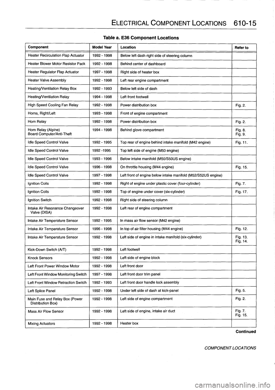
Table
a
.
E36
Component
Locations
Knock
Sensors
1
1992-1998
1
Left
side
of
engine
block
Left
Front
Power
Window
Motor
11992-1998
/
Left
front
door
Left
Front
Window
Monitoring
Switch
1
1997-1998
1
Left
front
door
trim
panel
Left
Front
Window
Retraction
Switch
1
1992
-
1993
1
Left
front
door
handle
lock
assembly
Left
Splice
Panel
1
1992-1998
1
Under
left
side
of
dash
at
kick-panel
1
Fig
.
5
.
Main
Fuse
and
Relay
Box
(Power
1992-1998
I
Left
sideof
engine
compartment
Fig
.
2
.
Distribution
Box)
1
I
Mass
Air
Flow
Sensor
1992-1998
I
Left
side
of
engine,
intake
air
duct
Fig
.
7
.1
I
Fig
.
15
.
Continued
COMPONENT
LOCATIONS
Page 526 of 759
ELE-42
ELECTRICAL
WIRING
DIAGRAMS
BC321
IGNITION
HEATED
__
COILS
HEATED
OXYGEN
ENGINE
(
SHIELD
I
IOXVGEN
II
SENBOR
I
(
CONTROL
I
(SENSOR
-~
SHIELD
I
(
MODULE
I
¢~
I
_I
(DME)
CONTROL
HEATED
I
(MODULE
I
(OXYGEN
I
_-J(OME)
ISENSOR2
0-0
G103
(M3CANADA)
IGNITION
CRANKSHAFT
I
COILS
I
I
POSITIONIRPM
SHIELD
k=__SENSOR
-
SHIELD
I
ENGINE
I-
CONTROL
I
I
MODULE
SRN
IL
1
G123
(3251)
ENGINE
I
(CONTROL
I
(MODULE
I
_
I
(DME)
BRNIORG
BRN/ORG
BRN
3
G119
(3201
.
3251
.
M3
CANADA)
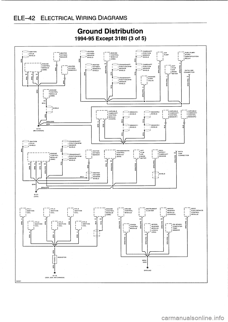
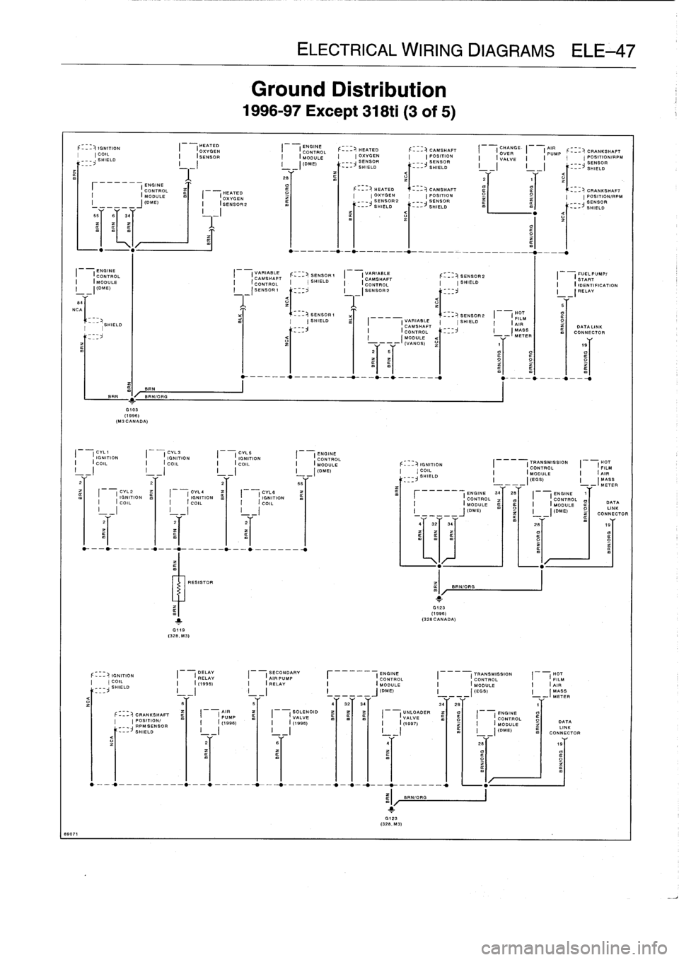
Ground
Distribution
1994-95
Except
318ti
(3
of
5)
HEATED
(OXYGENSENSOR,--
SHIELD
F
_~
HEATED
(OXYGEN
NCA~
_
_~
SENSOR
--
SHIELD
---
I
VARIABLE
CAMSHAFT(CONTROL
I
I
MODULE
----
(VANOS)
CRANKSHAFT
CRANKSHAFT
POSITION/RPM
SENSOR
---~
SHIELD
CAMSHAFT
POSITION
I
I
AIR
PUMP
CAMSHAFT
POSITION/RPM
I
POSITION_
_
I
I
HOT
__
SENSOR
_
SENSOR
FILM
-~SHIELD
-~
SHIELD_
I
I
AIR
M<
I
I
MASS
z
-
--
ETER
m
SENSOR
1
SHIELD
SENSOR
1
SHIELD
-
SENSOR
METER
I
(DME)
_~
SHIELD
19
3y
1Y
__
I
-
I
I
BT
_
I
_
<
557
By
347
287
T
oI
RESISTOR
BRN/I
ORG
_
SENSOR
---~
SHIELD
I
II
v
I
I
(CHANGE-
I
I
19
OVER
I
I
VALVE
_I
m
F---D,SENSOR2
I
(VARIABLE
I
(VARIABLESHIELD
CAMSHAFT
CAMSHAFTS
I
I
(CONTROL
I
(CONTROL
I
-
ISENSORI
I
-
I3ENSOR2
SENSOR2
I
SHIELD
1
GROUND
HEATED
TRANSMISSION
HOT
HALL
I
(
OXYGEN
I
(CONTROL_
I
(
FILM
I(
EFFECT
CRANKSHAFT
I;
SENSOR
I
(MODULE
I
(AIR
I
(CAMSHAFT
POSITION/RPM
I
(EGS)I
MASS
I
I
SENSOR
._
II
(SHIELD
I
FUEL
PUMPf
START
I
I
IDENTIFICATION
I
v
I
RELAY
197
L
DAN
TA
K
I
oICONNECTOR
DATA
LINK
CONNECTOR
I
CYL1
(
ICYL3
I
CYL5
I
(ENGINE
I
(CRUISE
I
(INSTRUMENT
I
(
WIPER/
I
BODY
IGNITION
IGNITION
IGNITION
ONTROL
CONTROL
CLUSTER
WASHER
ELECTRONICS
I
;
COIL
I
(
COIL
I
(
COIL
I
IC
MODULE
I
(
MODULE
I
I
I
(
MODULE
I
(
CONTROL
I
_I
I
_I
I
_I
I
-
I
(DME)
I
_
I
(CANADA)
MODULE
2
2
2
1565
17
26
25
B
CYL2
CYL4
CYLS
U
o
I
(
IGNITION
m
I
(
IGNITION
z
I
(
IGNITION
I
(
COIL
I
(
COIL
I
(
COIL
CRASH
WIPER/
ON
-BOARD
I
I
I
I
I
I
CONTROL
rt
WASHER
O
COMPUTER
I
I
I
I
I
I
I
(MODULE
I
(
MODULE
I
(TEMP
2T2Y
.
.
F_
_
I
-I
I
_
I
(
I)
I
-
I
SENSOR
2
Y
USA)
-
,
Page 531 of 759
8907
1
I
(ENGINE
CONTROL
I
(MODULE
I
-
I
(ONE)
84
NCA
I
F-_
_
)1
I
IGNITIONCOIL
SHIELD
u
CONTROL
HEATED
I
(MODULE
I
(OXYGEN
I
-
I(DME)_
ISENSOR2
55
fi
34
I
~BR~N
BR=
m
I
B~
RN/OPG
G103
(1996)
(M3
CANADA)
I
OXYGEN
(HEATED
ENGINE
I
(CONTROL_
HEATED
I
(SENSOR
I
(MODULE
I
(OXYGEN
I
IGNITION
I
I
IGNITION
¢
I
I
IGNITION
COIL
I
i
COD
.
I
I
COIL
I
_~
I
_I
I
_I
1
G,19
(328,
M3)
RESISTOR
Ground
Distribution
1996-97
Except
318ti
(3
of
5)
(
-
I
(DIVE)
SENSOR
SHIELD
28
I
(VARIABLE
SENSOR(
I
(VARIABLE
SENSOR2
FUEL
PUMP/
CONTROL
(SHIELD
CAMSHAFT
I
(START
C
I
I
I
(
CONTROL
SHIELD_
I
(
IDENTIFICATION
I
_
(SENSOR(
ISENSOR2
_
(RELAY
1
II
I5
SENSOR2
I
(HOT
_-~
SENSOR1
FILMSHIELD
I
(
VARIABLE
I
-(
SHIELD
I
(
AIR
CAMSHAFT
DATA
INK
I
(CONTROL
<1-_-~
I
(MASS
I
ml
CONNECTOR
(VANCE)
19
CVL1
CVL3
CVLE
ENGINE
(
IGNITION
I
(
IGNITION
I
(
IGNITION
i
(
CONTROL
I
(
COIL
I
(
COIL
I
(
COIL
I
(
MODULE
I
_I
I
_I
I
_I
I
_I
(DME)
ELECTRICAL
WIRING
DIAGRAMS
ELE=47
F---
HEATED
CAMSHAFT
I
I
OXYGEN
I
I
POSITION
SENSOR2
SENSOR--
SHIELD
--
SHIELD
mI
I
-
-
------------
-
-
-
4/
32/34/
341
26
j
.123
(328,M3)
_-~CAMSHAFT
I
ICHANGE
I
(PUMP
F---~
CRANKSHAFT
(
POSITION_
I
(
VALVE
I
(
POSITION/PPM
_
SENSOR
__
SENSOR
--~
SHIELD
SHIELD
IGNITION
TRANSMISSION
HOT
(
COIL
I
(
CONTROL
I
(
FILM
__
SHIELD
_
I
(
MODULE
I
(
AIR
_I(EGS)
I
(MASS
---
_
METER
ENGINE
3428
M
I
I
ENGINE
r
-I
(
ECONTROL
O
CONTROL
I
(ODULE
ml
¢O
I
(ODULE
DATA
M
I
-
j
(DIVE)
I
-
I
(DIVE)
¢I
LINK
CONNECTOR
Y
YY
.
.
G123
(1996)(328
CANADA)
BRN/ORG
O
IGNITION
DELAY
SECONDARY
ENGINE
TRANSMISSION
HOT
COIL
I
(
RELAY
I
I
AIR
PUMP
F
(
CONTROL
I
(
CONTROL
I
(
FILM
SHIELD
I
(
(1996)
I
(
RELAY
I
(
MODULE
I
(
MODULE
i
(
AIR
L
_
_I
I
I
I
__
__J(OME)
I
_
I(EGSI
MASS
_
I
-(MATS
YY
Y
v
CRANKSHAFT
AIR
I
SOLENOID
UNLOADER
I
(ENGINE
O
(
PUMP
I(
VALVE
(VALVE
CONTROL
POSITION/_
m
I
(
(1998)
m)
I
(
(1996)
(
(1997)
I
(
MODULE
DATA
_
RPMSENSOR
LINK
SHIELD
I_-
I
I
-
I
I
_I
I
_I
(DM
E)
CONNECTOR
zBY
,9T
CRANKSHAFT
I
POSITION/RPM
1
(MODULE
-
_
METER
SENSOR--
SHIELD
Page 532 of 759
ELE-48
ELECTRICAL
WIRING
DIAGRAMS
TRANSMISSION
r
I
ENGINE
(HALL
CON
TROL
I
CONTROL
I_
(
I
EFFECT
I
(
MODULE
I
(
MODULE
I
(
CAMSHAFT
I
_____y
_
I
11"S)
1
--
j
(DIE)
I
(SENSOR
B'f
28
y_
1
..'r
BY
3ar
BET
26
~
3
8907
2
PASSENGERS
PASSENGERSPASSENGERS
PASSENGERS
SUPPRESSION
DRIVERS
DOOR
DRIVER
I
(DOOR
I
(
SEAT
I
(SEAT
I
I
SEATBACK
I
(
FILTER
I
(
WINDOW
I
(
LOCK
I
(
DOOR
I
(JAMB
I
(CONTROL
I
(HEATER
I
(HEATER
II
I
(MOTOR
I
(HEATER
I
(HANDLE
RIGHT
RIGHT
RIGHT
CD
I---
m
I
-
I_
i
II
REAR
REAR
REAR
CHANGER
(
INTERIOR
I
I
(
WINDOW
ml
I
(
INTERIOR
ml
I
I
1
G313
G302
(4
DOOR)
(1996)
ROLLOVER
CONVERTIBLE
CONVERTIBLECONVERTIBLE
CONVERTIBLE
WINDSCREEN
HIFI
RADIO
I
(
SENSOR
I
---
(
TOP
I
(
TOP
I
(
TOP-END
I
---
(
TOP
I
I
CoWLPANEL
I
(
AMPLIFIER
I
II
I
I
(
ACTUATING
I
I
OONTROL
I
(
POSITION
I
(
POSITION
I
(
LOCK
I
i
I
I
SWITCH
I
-(
MODULE
I
-(
SWITCH
I
,
---(
SWITCH
I
,-(
SWITCH
I
-I
1
-I
IGNITION
F---
CRANKSHAFT
I
(HOT
I
I
UNLOADER
1
'CYL1
IOYL3
COIL
POSITION
FILM
RELAY
IGNITIONIGNITION
I
I
(
AIR
I
(
(1997)
I
(
COIL
I
(
COILCOILSHIELD
_
SENSOR
SHIELD
MASS
METER
S
1
(
I
I
I
I
1
I
___
1
r
(
1996
)
.T
2T
21"
,
.-------
.
.W_-*---___--7-----__-41"
-
----___--0-f---_---7
1
.1
m
SEAT
CHECK
LEFT
ANTI-
RIGHT
DRIVERS
PASSENGERS
I
(
OCCUPANCY
I
(
CONTROL
I
(
REAR
I
(
THEFT
I
(
REAR
I
(
SEATBELT
I
(
SEAT
I
1
DETECTOR
I
(
MODULE
I
(
DOOR
I
(
CONTROL
I
(
DOOR
I
I
SWITCH
I
T
HEATER
1
_I
I
-I
L-1
CONTACT
I
-I
MODULE
I
-I
CONTACT
I
-I
I
_
I
SWITCH
I
PASSENGERS
9
I
'
DRIVERS
4
PASSENGERS
DRIVERS
1
PASSENGERS
1
4
DRIVERS
(
WINDOW
WINDOW
I
(
SIDE
I
(
SIDE
I
(
SEATBELT
I
(
SEA
2
T
I
I
MONITIORING
I
I
MONITIORING
I
(
IMPACT
I
(
IMPACT
I
(
SWITCH
I
(
HEATER
1
(
SWITCH
I-.(
SWITCH
I
V
I
SENSOR
I
v
I
SENSOR
I
5I
I
I
-(
-
(1997)
--
(1997)
--
(1997)
T
--
(1997)
SWITCH
-
Y
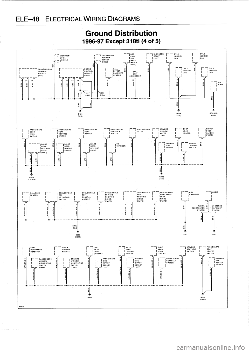
Ground
Distribution
1996-97
Except
318ti
(4
of
5)
i
997
__~
1996
m)
ONLYONLY
G123
GI9
GROUND
(318)
(318)
(318)
y
1
1
G203
G202
G202
(1996)
DATA
LINK
CONNECTOR
O
-___-___0_-t--__--_
.,---0__--_---`__
.,-_--_-_-*_--0
.-____-
CYL2
DYLa
I
I
IGNITION
I
I
IGNITION
I
I
m
COIL
l
I
I
COIL
1
'
o~
t
G302
(1996)
1
AIR
I
PUMP
31
3
aIaI¢~
W/HIFI
.
,I
W/STEREOTENSPEAKER6SPEAKER
SYSTEMSYSTEM
Page 554 of 759
ELE-70
ELECTRICAL
WIRING
DIAGRAMS
I
02
SENS
SIB
I"7
7
I
02SENSGNDI)
I
GROUNDI
2
BR
,
'IB
BRN/BLU
I
IARCVALVEI
I
IsCVALVEI}
I
ECM
RELAY
I
EEVALVEI~
I
CVL4IGNCOILI
S7~LK
I
CVL3IGNCOILI
24L
BL1(
I
CVL2IGN
COILI'
B2
~
BLK
I
CVLIIGNCOILI
2
I
GROUNDI
B'=RN
I
GF
.uNDI
),
BRN
I
GROUNOI
3~
BR"
I
RUNIST
GRN
ARTI
S~
ENGINECONTROL
MODULE
(DME)
13B
START
1
GRN
I
DN
OFF
IGNITION
S
WITCH
8727
3
HOTATALLTIMES
UELINJECTION
VALVES
NCA"
=
It,
INCA
SPIN
BRN
GRN
~GRN
OF
N
/
GRN"
\
GRN
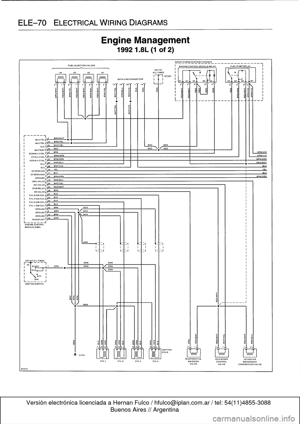
Engine
Management
19921
.8L
(1
of
2)
HOTAT
F4
X3X2
R1
ALLTIMES
I
XZ793
M
M
[]M[IM
AT
.
LINK
CONNECTOR
8B
3Dy
eB=85
.1
.1308
I
ii
w
>
3~
3
3
BRNIWH
INJCTRLI
32
BRNIYEL
T
INJCTRLI~
DLCI
je7
L
REO
I
RED
BATTERY
I
2S
RED
RED
FRONT_POWERDISTRIBUTIONBO%
_
_
___
_
_
_
____
_
_
I
ENGINE
CONTROL
MODULE
RELAY
FUEL
PUMP
RELAY
L
ECMFLY
CTRL
1)27
BFN
FP
FLY
CTRL
I
I'
SWORN
02SFLYCTRL
I
37
BRNIGRN
BRN
GRN
DLCI
80
GRNIBLU
RE
O
DLCI
,88
WHTIVIO
1
~1~
2oY
1
Y
I4Y
_
i
2Y
SY
BX
BY
4YBY
EVAPORATIVE
IDLESPEED
INTAKE
AIR
EMISSION
CONTROL
RESONANCE
VALVE
VALVE
CHANGEOVER
VALVE
Page 566 of 759
ELE-82
ELECTRICAL
WIRING
DIAGRAMS
I
AC7IVATEVALVEII
BRNIWHT
I
ACTIVATE
VALVE
I'3
BRN/V
EL
10862
4
SIGNPLINPUTI
1T2
B
AN
ACTIVATE
VALVE
I--
GROUND
I
4B6~GRV/VIO
ENGINO1CATOR
I
~
10
BLK/VIO
DRIVE
AWAY
SIG
II
11
BLKIGRY
AC
TIVATEAIC
ACTIVATE
VALVEI
31
BRNIBLU
ACTIVATE
VALVE
I
32~BRTI/GRN
120
BLK
CRANKPOSIRPMI
Y-
CAMSHAFTPOSI
21
I
BATTERYVOLTI126
RED
ECM
RLV
CTRL
1
)21
8RN/WHT
18
BRNIRED
INTKAIRTEMPI
I
I
406
CVL3-4KSI
42
GRNIRED
FU
ELCONSUMPTI
THROTTLE
POST
44
B
RN/VIO
I
A/CCOMPCUT136
8LK/BLU
"
8LK/BLU
II
5VSUPPLVI
53
ISCVALVE
CTRLI
2
/GRN
30
BRN
02SENSH7NGI~-
19
VEL
02SENSORSIGI~
1
BRN
02
SENS
HTNG
I
SENSORGRNOI
4
23
BLU
CVL4IGNCOIL
CVL3
ON
co
ILI
2r-
INJGROUND
I
128
BRN
GROUND
GROUNDI)~pl
L_____!
ENG
ME
CONTROL
MODULE
(DME)
HOTPTALLTIMES
___
I
START
.1
1
GRN
I
RUN
~_I
I
18
I
~
ACC
I
OFF
IGNITION
SWITCH
BA7TERVVOLTI
54
RED/W~
H
IGNGROUNDI
50
READ
CYL21GN
COIL
ED
I
l
~~
CYL1IGNCOIL
49
WHT
I
IGNSWITCH
I
56
GR
"GRN
B7
REOIWHT
ACTIVATE
FAN
ACTIVATE
VALVE
I
8
tf
FUELINJECTIONVALVES
HALLEFFECT
HOTFILMAIR
CAMSHAFT
FRONT
POWER
DISTBIU710NBOX
______
.
___
CVL4CVL3
CVL2
CYLl
MASSMETERSENSOR
r
i
SYSTEM
NORMAL
SPEEDRELAY
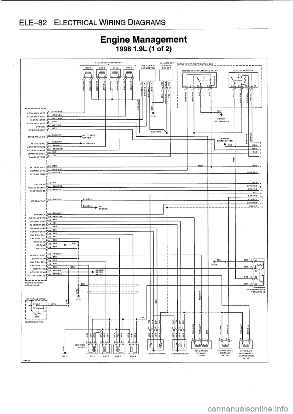
Engine
Management
19981
.9L
(1
of
2)
IGNITION
JJ
U
COILS
II
GA
.
4
3~2
1
a
mIm
a
OXVGENSENSOROXVGENSENSOR
IDLESPEED
EVAPORATIVE
INTAKEAIR
CONTROL
EMISSION
RESONANCE
VALVEVALVE
CHANGEOVER
VALVE
I
-
"HIRED
2
Page 754 of 759
WARNING
Your
common
sense,
good
judge-
ment,
and
general
alertness
are
cru-
cial
tosafe
and
successful
service
work
.
Before
attempting
any
work
on
your
BMW,
read
the
warnings
and
cautions
on
page
vi¡
and
the
copyright
page
at
the
frontof
the
manual
.
Review
these
warnings
and
cautions
each
time
you
prepare
to
work
on
your
BMW
.
Please
also
read
any
warnings
and
cautions
that
accom-
pany
the
procedures
in
the
manual
.
Fuel
pressure
regulator
See
Fuel
injection
Fue]
pump
general
information
160-1
electrical
tests
160-7
power
consumption,
testing
160-7
delivery
tests160-8
delivery
volume,
testing
g
160-9
electrical
circuit,
checking
160-7
fuse
and
relay
160-6
level
sender
See
pump/fuel
leve¡
sender
operating
fuel
pump
for
tests
160-6
pump/fuel
level
sender
(left
side),
removing/installing
160-6
pump/fuel
leve¡
sender
(right
side),
removing/installing
160-5
relieving
fuel
pressure
and
connecting
fue¡
pressure
gauge
160-8
Fueltank
and
lines
general
information
160-1
draining
160-2
evaporative
control
system
160-4
leve¡
senders,
testing
160-5
removing/installing
160-3
Fundamentals
for
the
do-it-yourself
owner
general
information
010-1
advice
for
the
beginner
010-4
cleanliness
010-4
electrical
testing
010-6
gaskets
and
seals
010-5
non-reusable
fasteners
010-5
planning
ahead
010-4
tightening
fasteners
010-5
wire
repairs
010-6
buying
parts
010-6
genuine
BMW
parts
010-6
information
you
need
to
know
010-7
non-returnable
parts
010-7
emergencies
010-11brake
fluid
leve¡
010-13
car
will
not
start
010-11
changinga
tire
010-11
check
enginewarning
light
010-13
dim
Iights
010-13
jump
starting
car
010-12
low
o]I
pressure
010-13
overheating
010-12
Emergencies
(cont
.)
spare
parts
kit
010-14
towing
010-13
gettingstarted
010-2
lifting
thecar
010-3
raising
car
safely
010-3
safety
010-2
working
under
car
safely
010-4
how
to
use
this
manual
010-2
warnings,
cautions
and
notes
010-2
service
010-7
tools
010-7
basic
tool
requirements010-8
BMW
specialtools
010-11
feeler
gauges
010-10
jack
stands
010-9
oil
change
equipment
010-9
torque
wrench
010-10
volt-ohm
meter
(VOM)
or
Multi-
meter010-10
Fuses
See
Electrical
component
locations
G
Gaskets
See
Fundamentals
for
the
do-it-
yourself
owner
Gearshift
See
Gearshift
linkage
Gearshift
linkagegeneral
information
250-1
automatic
shiftlock,
checking
function
250-5
automatic
transmission
gearshift
250-
3
gear
position/neutral
safety
switch,
replacing
(automatic
transmission)
250-4
gearshift
lever,
installing
(manual
transmission)
250-2
gearshift
lever,
removing
(manual
transmission)
250-1
gearshift
mechanism,
adjusting
(automatictransmission)
250-3
manual
transmission
gearshift
250-1
shift
interlock,
checking
function
(automatic
transmission)
250-6Glass
See
Door
windows
Glove
compartment
See
Interior
trim
Grille
See
Exterior
trim,
bumpers
Guibo
(flex
disc)
See
Driveshaft
Handle,
door
See
Doors
Hardtop
See
Body-general
Headlight
See
Exterior
lighting
Headlight
switch
See
Switches
and
electrical
accessoriesHeater
box
See
Heating
Heater
core
See
Heating
Heater
valve
See
Heating
Heating
general
information
640-1
air
distribution
motors
640-9
air
distribution
motor,
replacing
(rotary
knob)
640-10
blower
motor,
removing/installing
640-1blower
motor
resistor
pack,
replacing
640-3
control
head
640-7
removing/installing
(digital-display)
640-8
removing/installing
(rotary
knob)
640-7
control
module
removing/installing
(digital-display)
640-8
removing/installing
(rotary
knob)
640-8
heater
box,
removing640-4
heater
core,
replacing
640-6
heater
core
temperature
sensor,
replacing
640-7
heater
valve,
replacing
640-3
rear
window
blower
(convertible
models)
640-10
reas
window
defogger
640-10sensor
fan
forinterior
temperature,
replacing
640-9warnings
and
cautions
640-11
Hood
See
Fenders,
engine
hood
Idle
speed
See
Maintenance
program
Idle
speed
control
valve
See
Fuel
injection
Ignition
switch
See
Switches
and
electrical
accessories
INDEX
5