E36 m3 BMW M3 1993 E36 Workshop Manual
[x] Cancel search | Manufacturer: BMW, Model Year: 1993, Model line: M3, Model: BMW M3 1993 E36Pages: 759
Page 5 of 759
Foreword
This
service
manual
covers
1992
through
1998
BMW
3
Series
models,
and
is
specifically
de-
signed
to
cover
only
those
models
built
for
sale
in
the
United
States
.
BMW,
and
most
accessories
and
parts
sellers
specializing
in
BMWs,
refer
to
the
3
Seriescars
coveredby
this
manual
as
the
E36
model
.
The
code
"E36"
is
BMW's
internal
code
for
the
basic
plat-
form
sharedby
al¡
of
the
cars
coveredby
this
manual
.
Except
for
the
engine
and
a
few
other
compo-
nents,
the
models
coveredby
this
manual
share
many
of
same
components
suchas
suspension
parts,
body
panels,
and
the
interior
pieces
.
When
ordering
parts,
especially
body
parts,
knowing
the
E36
code
may
be
helpful
.
BMW
also
usesan
interna¡
code
for
the
enginesused
in
the
3
Series
models
.
Consult
the
text
in
the
100
Engine-General
repair
group
ofthis
manual
for
a
complete
listing
of
engine
codes
.
Engine
-
code
information
is
primarily
used
internally
by
BMW,
but
may
be
helpful
if
you
haveaccess
to
BMW
technical
information
.
Forthe
BMW
ownerwith
basic
mechanical
skills,
this
manual
gives
detailed
maintenance
and
re-
pair
information
.
In
addition,
the
BMW
owner
who
hasno
intention
of
working
on
his
or
her
own
car
will
findthat
owning
and
reading
this
manual
will
make
it
possibleto
be
better
informed
and
todis-
cuss
repairs
more
intelligently
with
a
professional
technician
.
This
manual
has
been
prepared
from
the
repair
information
that
BMW
provides
to
its
factory-trained
technicians
and
has
been
developed
primarily
with
the
do-it-yourself
BMW
owner
in
mind
.
The
aim
throughout
has
been
clarity
and
un-
derstanding
with
practical
descriptions,
step-by-step
procedures,
and
accurate
specifications
.
The
BMW
owner
intending
to
do
maintenance
and
repair
should
have
a
set
of
tools
including
a
set
of
metric
wrenches
and
sockets,
screwdrivers,
a
torque
wrench,
and
feeler
gauges,
since
these
ba-
sic
tools
will
beused
to
do
the
majority
of
the
maintenance
and
repair
procedures
described
in
this
manual
.
This
manual
includes
detailed
information
onthese
basic
tools
and
other
tips
for
the
begin-
ner
in
the
first
section
of
the
manual,
entitled
010
Fundamentals
for
the
Do-It-Yourself
Owner
.
For
some
of
the
repairs
described
in
this
manual,
BMW
technicians
use
special
tools
.
The
text
will
note
when
a
repair
requires
these
special
tools
and,
where
possible,
will
recommend
practica¡
alter-
natives
.
Page 15 of 759
Non-returnable
Parts
FUNDAMENTALS
FOR
THEDO-ITYOURSELF
OWNER
010-
7
Many
independent
repair
shops
make
a
point
of
using
genu-
Original
body
paneis
and
other
large
components
are
identi-
ine
BMW
parts,
even
though
they
may
at
times
be
more
expen-
fied
by
a
label
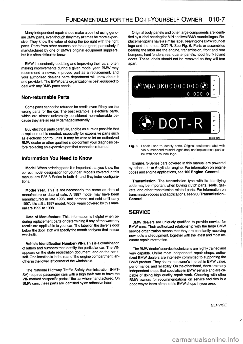
bearing
the
VINand
two
BMW
roundellogos
.
Re-
sive
.
Theyknow
the
value
of
doing
thejob
right
with
the
right
placement
parts
have
a
similar
label,
bearing
one
BMW
roundel
parts
.
Parts
from
other
sources
can
beas
good,
particularly
if
logo
and
the
letters
DOT-R
.
See
Fig
.
6
.
Parts
or
assemblies
manufactured
by
one
of
BMWs
original
equipment
suppliers,
bearing
the
label
arethe
engine,
transmission,
front
and
rear
but
it
is
often
difficult
to
know
.
bumpers,
front
fenders,
rear
quarter
paneis,
hood,
trunk
lid
and
doors
.
These
labels
shouldnot
be
removed
as
they
will
tear
BMW
is
constantly
updating
and
improving
their
cars,
often
apart
.
making
improvements
during
a
given
model
year
.
BMW
may
recommend
a
newer,
improved
part
as
a
replacement,
and
your
authorized
dealer's
parts
department
will
know
about
it
and
provide
it
.
The
BMW
parts
organization
is
best
equipped
to
deal
with
any
BMW
parts
needs
.
Some
parts
cannot
be
returned
for
credit,
even
if
they
arethe
wrong
parts
forthe
car
.
The
best
example
is
electrical
parts,
which
are
almost
universally
considered
non-returnable
be-
,
..
cause
they
are
so
easily
damaged
internally
.
Buy
electrícal
parts
carefully,
and
beas
sure
as
possible
that
P-
DOT~
R
a
replacement
is
needed,
especially
for
expensive
parts
such
as
electronic
control
units
.
It
may
bewise
to
let
an
authorized
B328FUN
BMW
dealeror
other
qualified
shop
confirm
your
diagnosisbe-
fore
replacing
an
expensive
part
that
cannot
be
retuned
.
Fig
.
6
.
Labels
used
to
identiy
parts
.
Original
equipment
labelwith
VIN
number
and
roundel
logos
(top)
and
replacement
part
la-
bel
with
one
roundel
logos
Information
You
Need
to
Know
Engine
.
3-Seriescars
covered
in
this
manualare
powered
Model
.
When
ordering
parts
it
is
important
that
you
know
the
by
either
a
4-or
6-cylinder
engine
.
For
information
-
on
engine
correct
model
designation
for
your
car
.
Models
covered
in
this
codes
and
engine
applications,
see100
Engine-General
.
manual
are
E36
3
Series
in
both
4-
and
6-cylinderconfigura-
tions
.
Transmission
.
The
transmissiontype
with
its
identifying
code
may
be
important
when
buying
clutch
parts,
seals,
gas
Moda¡
Year
.
This
is
not
necessarily
the
same
as
date
of
kets,
and
othertransmission-relatedparts
.
For
information
on
manufacture
or
date
of
sale
.
A
1997
model
may
havebeen
transmission
codes
and
applications,
see200
Transmission
manufactured
in
late
1996,
and
perhaps
not
sold
until
early
General
.
1997
.
It
is
still
a1997
model
.
Model
years
covered
by
this
man-
ual
are
1992
to
1998
.
SERVICE
Date
of
Manufacture
.
This
information
is
helpful
when
or-
dering
replacement
parts
or
determining
if
any
of
the
warranty
BMW
dealers
are
uniquely
qualified
to
provide
service
for
recalls
are
applicable
to
your
car
.
The
label
on
the
driver's
door
BMW
cars
.
Their
authorized
relationship
with
the
large
BMW
below
the
door
latch
will
specify
the
month
and
year
that
the
car
serviceorganization
means
that
they
are
constantly
receiving
was
built
.
new
tools
and
equipment,
together
with
the
latest
and
most
ac-
curate
repair
information
.
Vehicle
Identification
Number
(VIN)
.
This
is
a
combination
of
letters
and
numbers
that
identify
the
particular
car
.
TheVIN
appears
on
the
state
registration
document,
and
on
thecar
it-
self
.
One
location
isin
the
rear
of
the
engine
compartment,
en-
other
in
the
lower
left
comer
of
the
windshield
.
The
National
Highway
Traffic
Safety
Administration
(NHT-
SA)
requires
passenger
cars
with
a
high
theftrateto
have
the
VINmarked
on
specific
parts
of
thecar
when
manufactured
.
On
BMW
cars,
these
parts
are
identified
byan
adhesive
label
.
)WBADK00000000
0
000
0
The
BMW
dealers
service
technicians
are
highlytrained
and
very
capable
.
Unfke
most
independent
repair
shops,
autho-
rized
BMW
dealers
are
intensely
committed
tosupporting
the
BMW
product
.
They
share
the
owners
interest
in
BMW
value,
performance,
and
reliability
.
On
the
other
hand,
there
are
many
independent
shops
that
specialize
in
BMW
service
and
are
ca-
pable
of
doing
high
quality
repair
work
.
Checking
with
other
BMW
owners
for
recommendations
on
service
facilitiesis
a
good
way
to
leam
of
reputable
BMW
shops
in
yourarea
.
SERVICE
Page 30 of 759
020-
8
MAINTENANCE
PROGRAM
FLUID
AND
LUBRICANT
SPECIFICATIONS
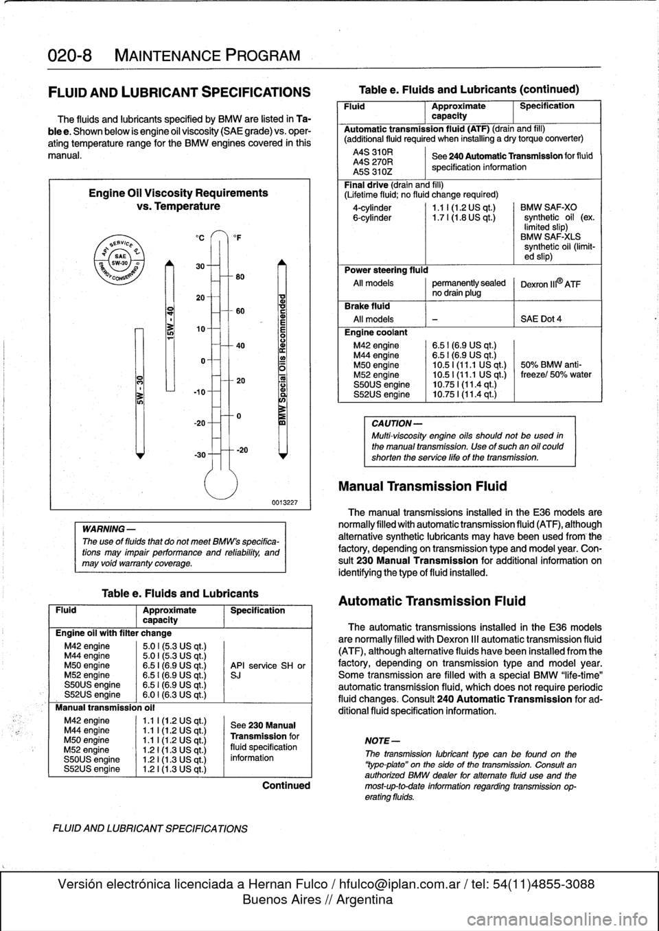
The
fluids
and
lubricante
specified
by
BMW
are
listed
in
Ta-
ble
e
.
Shown
below
is
engine
oil
viscosity
(SAE
grade)
vs
.
oper-
ating
temperature
range
for
the
BMW
enginescovered
in
this
manual
.
Engine
Oil
Viscosity
Requirements
vs
.
Temperature
`S
EAVic
P
Q
SAE
swao
YCO
0
N
M42
engine
1
.1
I
(1
.2
US
qt
.)
M44
engine
1
.1
l(1.2
US
qt
.)
M50
engine
1
.1
1(1.2
US
qt
.)
M52
engine
1
.21(1.3
US
qt
.)
S50US
engine
1
.21(1.3
US
qt
.)
S52US
engine
1
.21(1.3
US
qt
.)
°F
80
-
1o-0
-
30
-----20
WARNING
-
The
use
of
fluids
that
do
not
meet
BMWs
specifica-
tions
may
impair
performance
and
refability,
and
may
void
warranty
coverage
.
Tablee
.
Fluids
and
Lubricants
0013227
Fluid
Approximate
Specification
capacity
Engine
oil
with
filter
change
M42
engine
5
.01
(5
.3
US
qt
.)
M44
engine
5
.0
I
(5
.3
US
qt
.)
M50
engine
6
.5
I
(6.9
US
qt
.)
API
service
SH
or
M52
engine
6
.51
(6.9
US
qt
.)
si
S50US
engine
6
.51
(6.9
US
qt
.)
S52US
engine
6.0
I
(6.3
US
qt
.)
Manual
transmission
oil
FLUID
AND
LUBRICANT
SPECIFICATIONS
See
230Manual
Transmission
for
NOTE-
fluid
specification
Tablee
.
Fluids
and
Lubricants
(continued)
Fluid
Approximate
Specification
capacity
Automatic
transmission
fluid
(ATF)
(drain
and
fill)
(additional
fluid
required
when
installing
a
drytorque
converter)
A4S
310R
See240
AutomaticTransmission
for
fluid
A4S
270R
specification
information
A5S
310Z
Final
drive
(drain
and
fill)
(Lifetime
fluid
;
no
fluid
change
required)
4-cylinder
1
.1
I
(1.2
US
qt
.)
BMW
SAF-XO
6-cylinder
1.7
l(1
.8
US
qt
.)
synthetic
oil
(ex
.
limited
slip)
BMW
SAF-X1-S
synthetic
oil
(limit-
ed
slip)
Power
steering
fluid
Al¡
modeis
permanentlysealed
Dexron
IIPATFno
drain
plug
rake
fluid
All
modeis
-
~
S
AE
Dot4
Engine
coolant
M42
engine
6
.51(6
.9
US
qt
.)
M44
engine
6
.51(6
.9
US
qt
.)
M50
engine
10
.51
(11
.1
US
qt
.)
50%
BMW
anti-
M52
engine
10
.5
1
(11
.1
US
qt
.)
freezel
50%
water
S50US
engine
10
.75
1(11
.4
qt
.)
S52US
engine
10
.75
I
(11
.4
qt
.)
CA
UTION-
Multi-viscosity
engine
oils
should
not
beused
in
the
manual
transmission
.
Use
of
such
an
oil
could
shorten
the
service
life
of
thetransmission
.
Manual
Transmission
Fluid
The
manual
transmissions
installed
in
the
E36
modeis
are
normallyfilled
with
automatic
transmission
fluid
(ATF),
although
alternative
synthetic
lubricants
may
havebeen
used
from
-
the
factory,
depending
on
transmission
type
and
model
year
.
Con-
sult
230
Manual
Transmission
for
additional
information
on
identifying
the
type
of
fluid
installed
.
Automatic
Transmission
Fluid
The
automatic
transmissions
installed
in
the
E36
modeis
are
normally
filled
with
Dexron
111
automatic
transmission
fluid
(ATF),
although
alternative
fluids
havebeen
installed
from
the
factory,
depending
on
transmission
type
and
model
year
.
Some
transmission
are
filled
with
a
special
BMW
"life-time"
automatic
transmission
fluid,
whích
does
not
requireperiodic
fluid
changes
.
Consult
240
Automatic
Transmission
for
ad-
ditional
fluid
specification
information
.
information
1
The
11-
11
lubrican
type
canbefound
on
ti
¡e
`Yype
plate"
on
the
side
of
the
transmission
.
Consult
an
authorized
BMW
dealer
foralternate
fluid
use
and
the
Continued
most-up-to-date
information
regarding
transmission
op-
erating
fluids
.
Page 34 of 759
020-
1
2
MAINTENANCE
PROGRAM
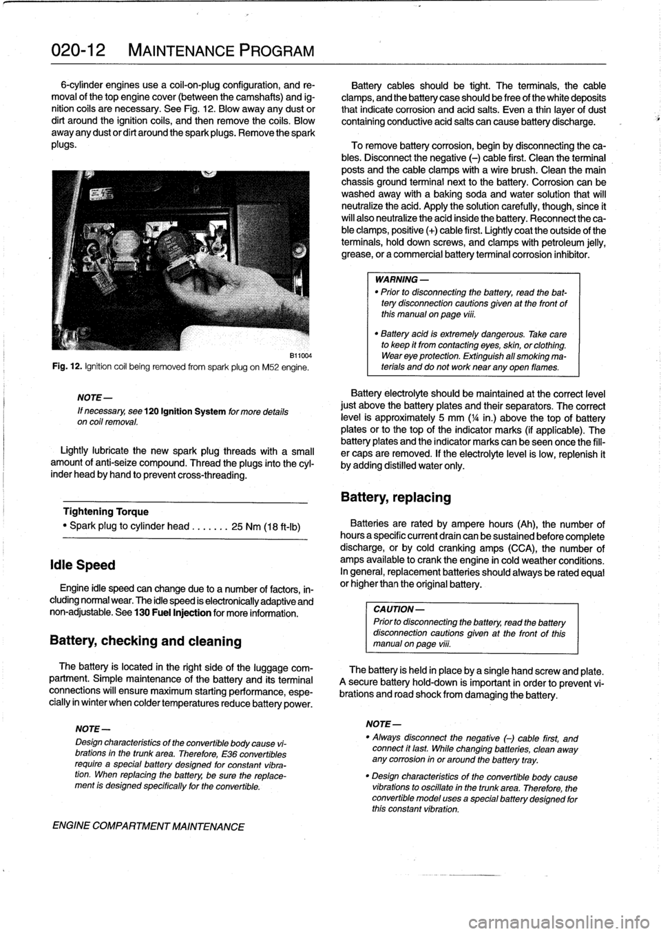
6-cylinder
engines
use
a
coil-on-plug
configuration,
and
re-
Battery
cablesshould
be
tight
.
The
terminals,
the
cable
moval
of
thetop
engine
cover
(between
the
camshafts)
and
ig-
clamps,
and
the
battery
case
should
be
freeof
the
white
deposits
nition
cofs
are
necessary
.
See
Fig
.
12
.
Blow
away
any
dust
or
that
indicate
corrosion
and
acid
salts
.
Even
a
thin
¡ayer
of
dust
dirt
around
the
ignition
coils,
and
then
remove
the
coils
.
Blow
containing
conductive
acid
salts
can
cause
battery
discharge
.
away
any
dustor
dirt
around
the
sparkplugs
.
Remove
the
spark
plugs
.
To
remove
battery
corrosion,
begin
by
disconnecting
theca-
bles
.
Disconnect
the
negative
(-)
cable
first
.
Clean
the
terminal
posts
and
the
cable
clamps
with
a
wire
brush
.
Clean
the
main
chassis
ground
terminal
next
to
the
battery
.
Corrosion
can
be
washedaway
with
a
baking
soda
and
water
solution
that
will
neutralize
the
acid
.
Apply
the
solution
carefully,
though,since
ít
will
also
neutralize
the
acid
inside
the
battery
.
Reconnect
the
ca-
ble
clamps,
positive
(+)
cable
first
.
Lightly
coat
the
outside
of
the
terminals,
hold
down
screws,
and
clamps
with
petroleum
jelly,
grease,
or
a
commercial
battery
terminal
corrosion
inhibitor
.
Fig
.
12
.
Ignition
coil
being
removed
from
spark
plug
on
M52
engine
.
NOTE-
If
necessary,
see
120
Ignition
System
for
more
details
on
coil
removal
.
B11004
Lightlylubricate
the
new
spark
plug
threads
with
a
small
amount
of
anti-seize
compound
.
Thread
the
plugs
into
the
cyl-
inder
head
byhand
to
prevent
cross-threading
.
Tightening
Torque
"
Spark
plug
to
cylinder
head
.......
25
Nm
(18
ft-ib)
Idie
Speed
Engine
¡dle
speed
canchange
due
to
a
number
of
factors,
in-
cluding
normal
wear
.
The
idle
speed
is
electronically
adaptive
and
non-adjustable
.
See
130
Fuel
Injection
for
more
information
.
Battery,
checking
and
cleaning
The
battery
is
located
in
the
right
side
of
the
luggage
com-
partment
.
Simple
maintenance
of
the
battery
and
its
terminal
connections
will
ensure
maximum
starting
performance,
espe-
cially
in
winter
when
colder
temperaturesreduce
battery
power
.
ENGINE
COMPARTMENT
MAINTENANCE
WARNING
-
"
Prior
to
disconnecting
the
battery,
read
the
bat-
tery
disconnection
cautions
given
at
the
front
of
this
manualonpage
viii
.
"
Battery
acid
is
extremely
dangerous
.
Take
care
to
keep
it
from
contacting
eyes,
skin,
or
clothing
.
Wear
eye
protection
.
Extinguish
all
smoking
ma-
terials
and
do
not
worknear
any
oyen
flames
.
Battery
electrolyte
should
be
maintained
at
the
correct
level
just
above
the
battery
plates
and
their
separators
.
The
correct
leve¡
is
approximately
5
mm
(
1
/4
in
.)
above
thetop
of
battery
plates
orto
thetop
of
the
indicator
marks
(if
applicable)
.
The
battery
plates
and
the
indicator
marks
can
beseen
once
the
fill-
er
caps
are
removed
.
If
the
electrolyte
level
is
low,
replenish
it
by
adding
distilled
water
only
.
Battery,
repiacing
Batteries
are
rated
by
ampere
hours
(Ah),
the
number
of
hoursa
specific
current
draín
can
be
sustained
before
complete
discharge,
or
by
cold
cranking
amps
(CCA),
the
number
of
amps
available
to
crank
the
engine
in
cold
weather
conditions
.
In
general,
replacement
batteries
should
alwaysbe
rated
equal
or
higherthan
the
original
battery
.
CAUTION-
Prior
to
disconnecting
the
battery,
read
the
battery
disconnection
cautions
given
at
the
front
of
thls
manual
on
page
viii
.
The
battery
is
held
in
place
bya
single
hand
screw
and
píate
.
A
secure
battery
hold-down
is
important
in
order
to
prevent
vi-
brations
and
road
shock
from
damaging
the
battery
.
NOTE-
NOTE-
"
Always
disconnect
the
negative
()
cable
first,
and
Design
characteristics
of
the
convertible
body
cause
vi-
connect
ft
last
While
changing
batteries,
clean
away
brations
in
the
trunk
area
.
Therefore,
E36
convertibles
any
corrosion
in
or
around
the
battery
tray
.
require
a
specialbattery
designed
for
constant
vibra-
tion
.
When
repiacing
the
battery,
be
sure
the
replace-
"
Design
characteristics
of
the
convertible
body
cause
ment
is
designed
specffically
for
the
convertible
.
vibrations
to
oscillate
in
the
trunk
area
.
Therefore,
the
convertible
model
uses
a
specialbattery
designed
for
this
constant
vibration
.
Page 39 of 759
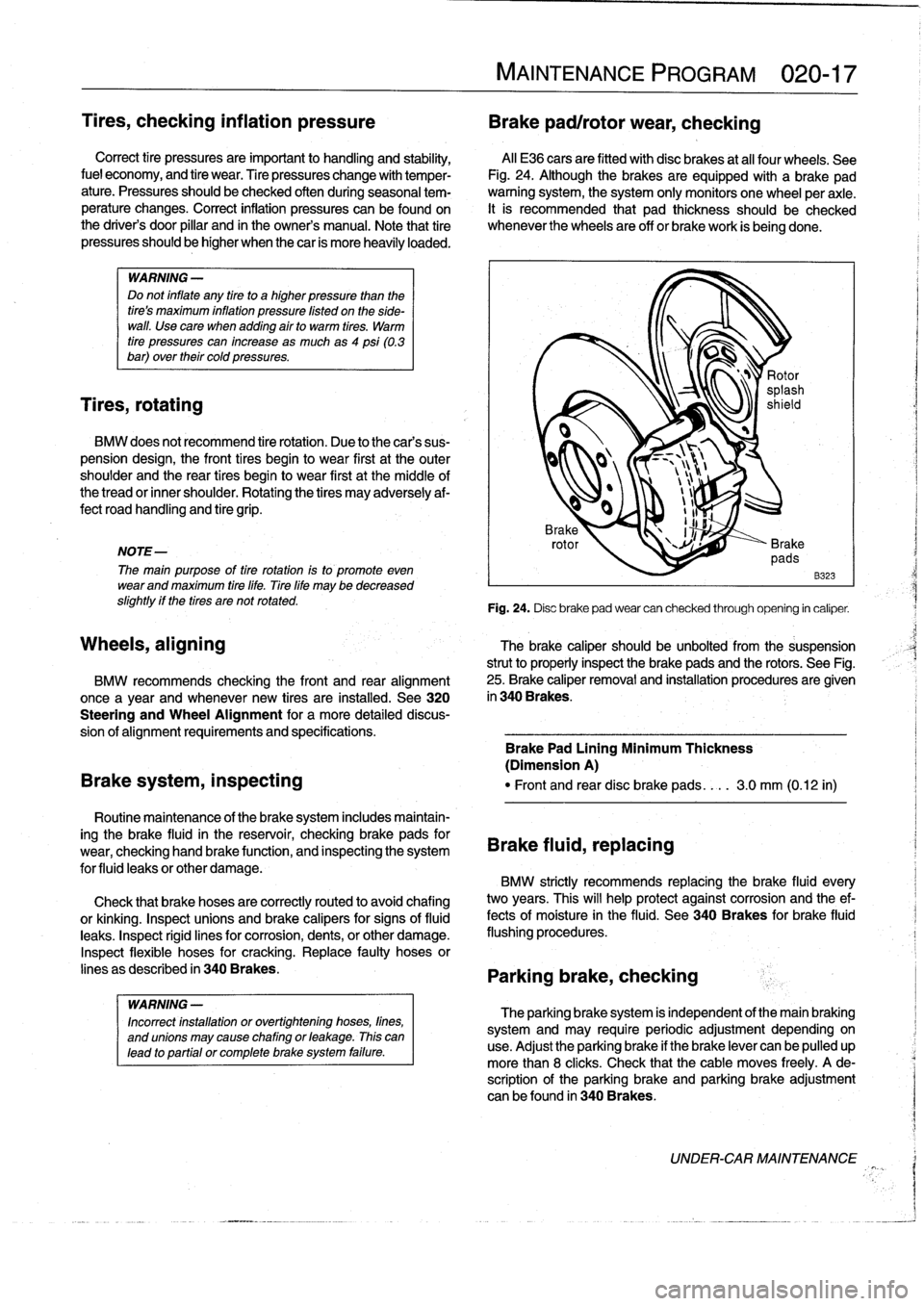
Tires,
checking
inflation
pressure
Brake
pad/rotor
wear,
checking
Correct
tire
pressuresare
important
to
handling
and
stability,
Al¡
E36
cars
are
fitted
withdisc
brakes
at
al¡
four
wheels
.
See
fuel
economy,
and
tire
wear
.
Tire
pressures
change
with
temper-
Fig
.
24
.
Although
thebrakesare
equipped
with
a
brake
pad
ature
.
Pressures
should
be
checked
often
during
seasonal
tem-
warning
system,
the
system
only
monitors
one
wheel
per
axle
.
perature
changes
.
Correct
inflation
pressures
canbe
found
on
It
is
recommended
that
pad
thickness
should
be
checked
the
driver's
door
pillar
and
in
the
owner's
manual
.
Note
that
tire
whenever
the
wheels
are
off
or
brakework
is
beggg
done
.
pressuresshould
be
higher
when
thecar
is
more
heavily
loaded
.
WARNING
-
Do
not
inflate
any
tire
to
a
higher
pressure
than
the
tiress
maximum
ínflation
pressure
listed
on
the
side-
wall
.
Use
cara
when
addlng
air
to
warm
tires
.
Warm
tire
pressures
can
increase
as
much
as4
psi
(0.3
bar)
over
their
cold
pressures
.
Tires,
rotating
BMW
does
not
recommend
tire
rotation
.
Due
to
the
cars
sus-
pension
design,
the
fronttires
begin
to
wear
first
at
the
outer
shoulder
and
the
rear
tires
begin
to
wear
first
at
themiddle
of
the
tread
or
inner
shoulder
.
Rotating
the
tires
may
adversely
af-
fect
roadhandling
and
tire
grip
.
NOTE-
The
main
purpose
of
tire
rotation
isto
promote
even
wear
and
maximum
tire
life
.
Tire
life
may
be
decreased
slightly
if
the
tires
are
not
rotated
.
Wheels,
aligning
Routine
maintenance
of
the
brake
system
includes
maintain-
ing
the
brake
fluid
in
the
reservoir,
checking
brakepads
for
wear,
checking
hand
brake
functíon,
and
inspecting
the
system
for
fluid
leaks
or
other
damage
.
Check
that
brake
hoses
are
correctly
routed
to
avoidchafing
or
kinkíng
.
Inspect
unions
and
brake
calipers
for
signs
of
fluid
leaks
.
Inspect
rigid
fines
for
corrosion,
dents,
or
other
damage
.
Inspect
flexible
hoses
for
cracking
.
Replace
faulty
hoses
or
lines
as
described
in
340Brakes
.
WARNING
-
Incorrect
installation
or
overtightening
hoses,
fines,
and
unions
may
cause
chafing
or
leakage
.
This
can
lead
to
partíal
or
completebrake
system
failure
.
MAINTENANCE
PROGRAM
020-
1
7
B323
Fig
.
24
.
Disc
brake
pad
wear
can
checked
through
opening
in
caliper
.
The
brake
caliper
should
be
unbolted
from
the
suspension
strut
to
properly
inspect
the
brake
pads
and
the
rotors
.
See
Fig
.
25
.
Brake
caliper
removal
and
installation
procedures
are
given
in
340
Brakes
.
BMW
recommends
checking
the
front
and
rear
alignment
once
a
year
and
whenever
new
tires
are
installed
.
See320
Steering
and
Wheel
Alignment
for
a
more
detailed
discus-
sion
of
alignment
requirements
and
specifications
.
Brake
Pad
Lining
Minimum
Thickness
(Dimension
A)
Brake
system,
inspecting
"
Front
and
reardisc
brake
pads
....
3
.0
mm
(0
.12
in)
Brake
fluid,
replacing
BMW
strictly
recommends
replacing
the
brake
fluid
every
two
years
.
This
will
help
protect
against
corrosion
and
the
ef-
fects
of
moisture
in
the
(luid
.
See340
Brakes
for
brake
fluid
flushing
procedures
.
Parking
brake,
checking
The
parking
brakesystem
is
independent
of
the
main
braking
system
and
may
requireperiodic
adjustment
dependingon
use
.
Adjust
the
parking
brake
if
the
brake
lever
can
be
pulled
up
more
than
8
clicks
.
Check
that
the
cable
moves
freely
.
A
de-
scription
of
the
parking
brake
and
parking
brake
adjustment
can
be
found
in
340Brakes
.
UNDER-CARMAINTENANCE
Page 43 of 759
GENERAL
.
.....
.
.
.
.
.
.
.
...
.
.
.
.
.
.
.
.
.
...
100-1
Cylinder
Block
and
Crankshaft
.
.
.
.
.
.
.
.
.
...
100-1
Connecting
Rods
and
Pistons
.
.
.
.
.
.
.
.
.
.
.
.
.
100-1
Cylinder
Head
and
Valvetrain
.
.
.
.
.
.
.
.
.
.
.
.
.
100-2
VANOS
(Variable
Valve
Timing)
.
.
.
.
.
.
.
.
...
100-2
DISA
(Dual
Resonance
Intake
System)
.
.
.
.
.
100-3
Engine
Management
System
.
.
.
.
.
.
.
.
.
.
.
.
.
100-3
Ignition
......
.
.
.
.........
.
.
.
.
.
.
.
.
.
.
.
.
100-5
Fuel
Delivery
..
.
.
.
.....
.
...
.
.
.
.
.
.
.
.
.
.
.
.
100-5
Cooling
System
.
...........
.
.
.
.
.
.....
.
.
100-5
Lubrication
System
.........
.
.
.
.
.
.
.
.
.
.
.
.
100-5
MECHANICALTROUBLESHOOTING
.
.
.
.
100-5
Warnings
and
Cautions
..
.
...
.
.
.
.
.
.
.
.
.
.
.
.
100-5
Cylinder
compression,
checking
.
.
.
.
.
.
.
.
.
.
.
100-6
EngineMechanical
Troubleshooting
Table
.
.
.
100-7
DRIVEABILITY
TROUBLESHOOTING
...
100-8
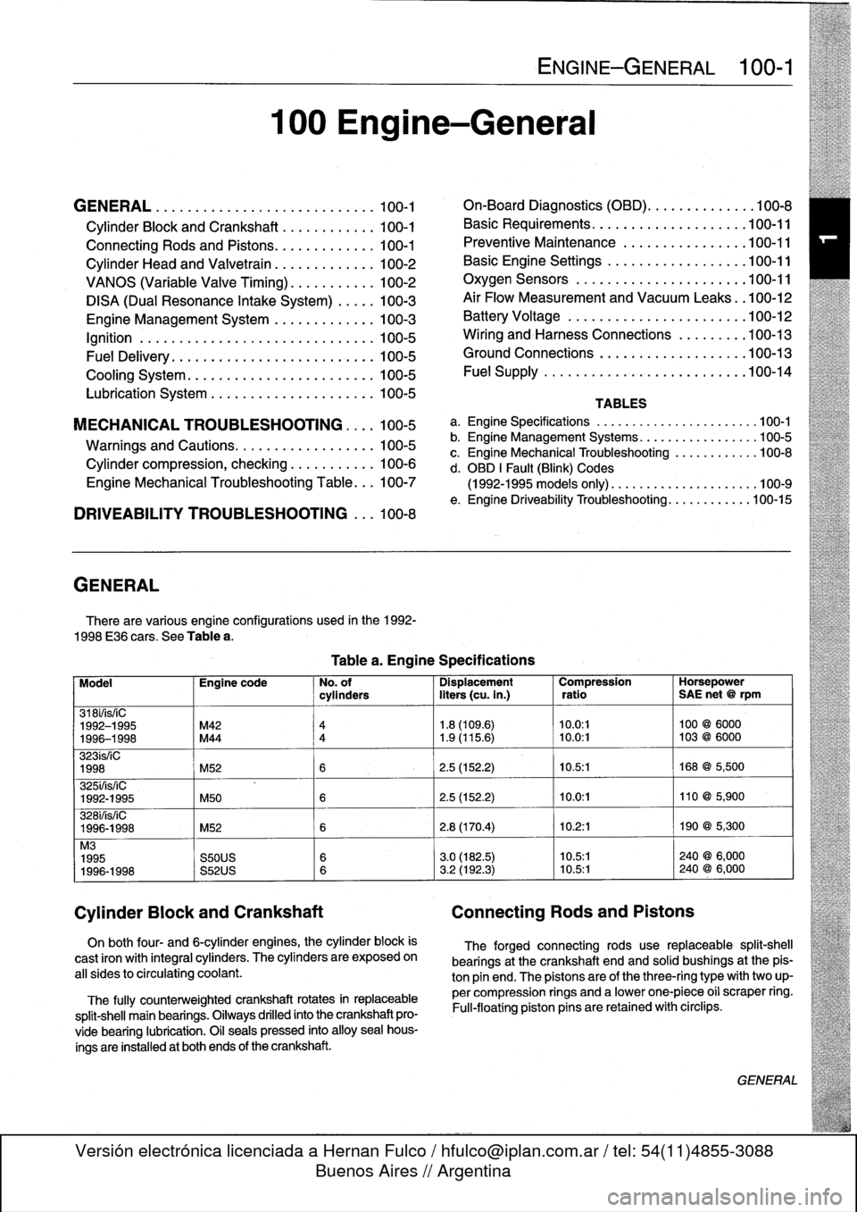
GENERAL
There
are
various
engíne
configurations
used
in
the
1992-
1998
E36
cars
.
See
Table
a
.
On
both
four-
and
6-cylinder
engines,
the
cylinder
block
is
cast
¡ron
with
integral
cyiinders
.
The
cyiinders
are
exposed
on
all
sides
to
circulating
coolant
.
The
fully
counterweighted
crankshaft
rotates
in
replaceable
split-shell
main
bearings
.
Oiiways
drilled
into
the
crankshaft
pro-
vide
bearing
lubrication
.
O¡I
seals
pressed
into
alloy
sea¡
hous-
ings
are
installedat
both
ends
of
the
crankshaft
.
100
Engine-General
Tablea
.
Engine
Specifications
ENGINE-GENERAL
100-1
On-Board
Diagnostics
(OBD)
...
.
.
.
.
.
.
.
.
.
.
.
100-8
Basic
Requirements
....
.
.
.
...
.
.
.
.
.
....
.100-11
Preventive
Maintenance
......
.
.
.
.
.
.....
100-11
Basic
Engine
Settings
..
.
.....
.
.
.
.
.
.....
100-11
Oxygen
Sensors
.
.
.
...
.
.
.
...
.
.
.
.
.
....
.100-11
Air
Flow
Measurement
and
Vacuum
Leaks
.
.100-12
Battery
Voltage
.
.
...........
.
.
.
.
.
.....
100-12
Wiring
and
Harness
Connections
.
.
.
.
.....
100-13
Ground
Connections
...
.
.....
.
.
.
.
.
.....
100-13
Fue¡
Supply
....
.
...........
.
.
..
.....
.100-14
TABLES
a
.
Engine
Specifications
...
...
...........
.
..
..
.100-1
b
.
Engine
Management
Systems
..
..
...........
..
100-5
c
.
Engine
Mechanical
Troubleshooting
..........
.
.
100-8
d
.
OBD
1
Fault
(Blink)
Codes
(1992-1995
models
only)
.
...
..
..
..........
..
.100-9
e
.
Engine
Driveability
Troubleshooting
...........
.100-15
Model
Engine
code
No
.
of
Dispiacement
Compression
Horsepower
cyiinders
liters
(cu
.
in
.)
ratio
SAE
net
@
rpm
318i/is/¡C
1992-1995
M42
4
1
.8
(109
.6)
10
.0
:1
100
@
6000
1996-1998
M44
4
1
.9
(115
.6)
~
10
.0
:1
103
@
6000
323ís/iC
1998
M52
6
2
.5
(152
.2)
10
.5
:1
168
@
5,500
325i/is/iC
1992-1995
M50
6
2
.5
(152
.2)
10
.0
:1
110
@
5,900
328i/is/iC
1996-1998
M52
6
2
.8
(170
.4)
10
.2
:1
190
@
5,300
M3
1995
S50US
6
3
.0
(182
.5)
10
.5:1
240
@
6,000
1996-1998
S52US
6
3
.2
(192
.3)
10
.5:1
240
@
6,000
Cylinder
Block
and
Crankshaft
Connecting
Rods
and
Pistons
The
forged
connecting
rods
use
replaceable
split-shell
bearings
at
the
crankshaft
endand
solid
bushings
at
the
pis-
ton
pin
end
.
The
pistonsare
of
the
three-ring
typewith
two
up-
per
compression
rings
and
a
lowerone-piece
o¡i
scraper
ring
.
Fui¡-floating
piston
pins
are
retained
with
circlips
.
GENERAL
Page 46 of 759
100-4
ENGINE-GENERAL
'
TEMP
PRECAT
POST
CAT
OXYGENSENSOR
HEATING
#
.
THROTTLE
POSITION
FUEL
INJECTOR
CONTROL
(SEQUENTIAL)
OPERATING
POWER
00
CAMSHAFT
POSITION
SENSOR
ECM
I
MAIN
GROUND
RELAY
J_
-
AC
COMPRESSOR
RELAY
CONTROL
TERMINAL
15
MEMORY
POWER
FUEL
PUMP
RELAY
CONTROL
AUX
GROUND
P
CRANKSHAFT
POSITION
dESENSOR
INTAKE
AIR
ENGINE
COOLANT
TEMP
FUEL
TANK
PRESSURE
SENSOR
S-EML
S-MSR
ASC
S-ASC
VEHICLE
SPEED
LOW
FUEL
LEVEL
A/C
SWITCH
ON
(AC)
E36
IHKA
COMPRESSOR"ON"
SIGNAL
(KO)
INDIVIDUAL
SERIAL
NUMBER
MS41
.1
SECONDARY
AIR
1NJECTION
AIR
PUMP®
RELAY
CONTROL
IDLE
CONTROL
VALVE
'M
FUEL
INJECTION
(TI)
ENGINE
SPEED
(TD)
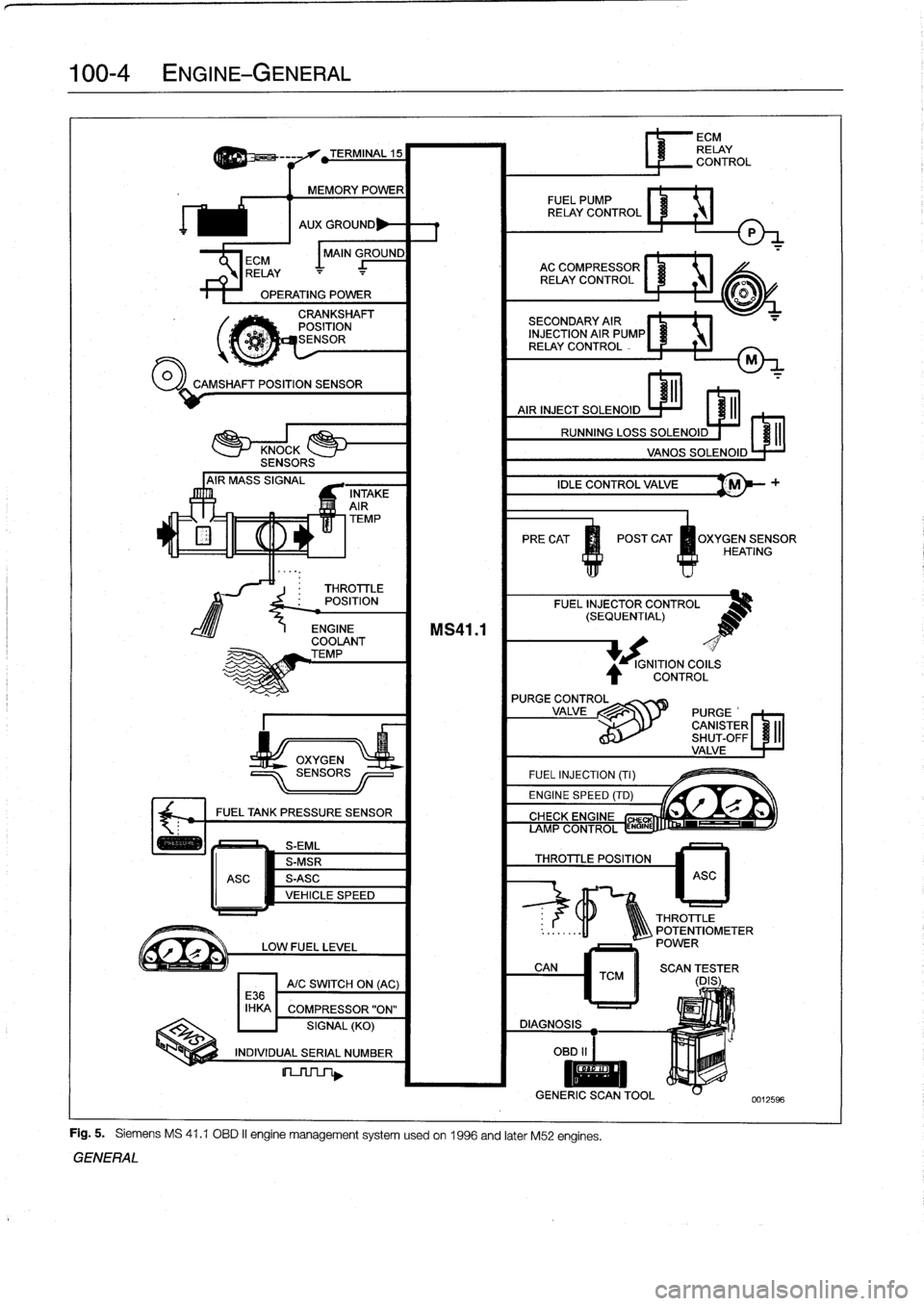
Fig
.
5
.
Siemens
MS
41
.1
OBD
II
engine
management
systemusedon
1996
and
later
M52
engines
.
GENERAL
IGNITION
COILS
CONTROL
L
r"Q
if~
CIYVFIYC
CHE
AMP
CONTROL
ENGINE
THROTTLE
POSITION
6
ECM
RELAY
CONTROL
ASC
THROTTLE
..
:
.
.
..
-11
1Q\\\
POTENTIOMETER
POWER
CAN
TCM
II
SCAN
(DES
;
ER
DIAGNOSIS
OBD
II
I
II
GENERIC
SCANTOOL
0012596
Page 137 of 759
CHARGING
SYSTEM
TROUBLESHOOTING
.............
.
.
.
.
.121-2
Charging
System
Quick-Check
...
.
..
.
...
.
121-2
Static
current
draw,
checking
........
.
...
.
121-2
BATTERY
SERVICE
....................
121-3
Battery
Testing
.
.
.
.
.
.........
.
........
.
121-3
Hydrometer
Testing
.
...
.
.
.
...
.
.........
121-3
Battery
Open-Circuit
Voltage
Test
....
.
....
121-4
Battery
Load
Voltage
Test
.
.
.
.
.
.
.........
121-4
Battery
Charging
.
.
.
.
...
.
.
.
.
.
.
.
.........
121-4
ALTERNATOR
SERVICE
.
.
.
.
.
.
.....
.
...
121-4
Chargingsystem,checking
.
.
.
.
.
.........
121-4
Alternator,
removingand
installing
(4-cylinder
engine)
....
.
.
.
.
.
.
.
.........
121-5
Alternator,
removingand
installing
(6-cylinder
engine)
..
.
.
.
.
.
.
.
.
.
.........
121-6
GENERAL
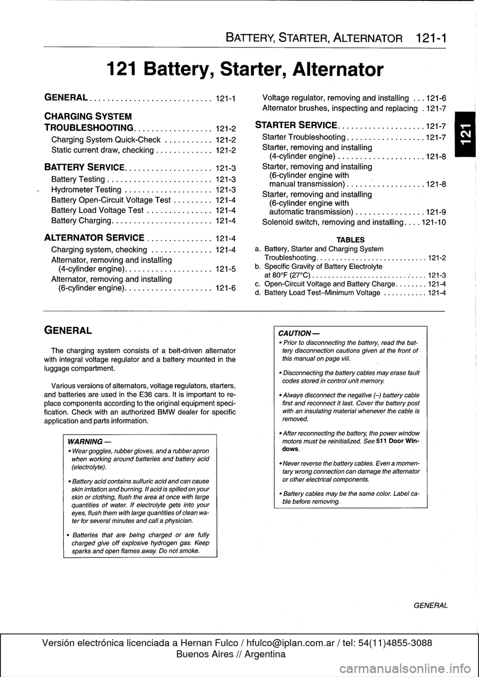
The
charging
system
consists
of
a
belt-driven
alternator
with
integral
voltage
regulator
and
a
battery
mounted
in
the
luggage
compartment
.
Various
versions
of
alternators,
voltage
regulators,
starters,
and
batteries
are
used
in
the
E36
cars
.
It
is
important
to
re-
place
components
according
tothe
original
equipment
speci-
fication
.
Check
with
an
authorized
BMW
dealer
for
specific
application
and
parts
information
.
WARNING
-
"
Weargoggles,
rubbergloves,
and
a
rubberapron
when
working
around
batteries
and
battery
acid
(electrolyte)
.
"
Battery
acid
contains
sulfuric
acid
and
can
cause
skin
irritation
and
burning
.
ff
acid
is
spilled
onyour
skin
or
clothing,
flush
the
area
at
once
with
large
quantities
of
water
.
lf
electrolyte
gets
into
your
eyes,flush
them
with
largequantities
of
clean
wa-
terfor
several
minutes
and
call
a
physician
.
"
Batteries
that
are
being
charged
or
are
fully
charged
give
off
explosive
hydrogen
gas
.
Keep
sparks
and
open
flames
away
.
Do
not
smoke
.
BATTERY,
STARTER,
ALTERNATOR
121-1
121
Battery,
Starter,
Alternator
GENERAL
..
.
...
.
........
.
...
.
.
.
.
.
.
.
.
.
121-1
Voltage
regulator,
removing
and
ínstalling
.
.
.
121-6
Alternator
brushes,
inspecting
and
replacing
.121-7
STARTER
SERVICE
....
.
.
.
.
.
..........
.121-7
Starter
Troubleshootíng
121-7
15
..
.
.
.
.
.
........
.
.
.
Starter,
removing
and
installing
(4-cylinder
engine)
....
.
.
.
............
.
121-8
Starter,
removing
and
installing
(6-cylinder
engine
with
manual
transmission)
..
.
...........
.
...
121-8
Starter,
removing
and
installing
(6-cylinder
engine
with
automatic
transmission)
................
121-9
Solenoid
switch,
removingand
installing
....
121-10
TABLES
a
.
Battery,
Starter
and
Charging
System
Troubleshooting
............
.
.
.
.
:...
........
121-2
b
.
Specific
Gravity
of
Battery
Electrolyte
at
80°F
(27°C)
...............
.
.
..
..........
121-3
c
.
Open-Circuit
Voltage
and
Battery
Charge
........
121-4
d
.
Battery
Load
Test-Minimum
Voltage
.
..........
121-4
CAUTION
-
"
Prior
to
disconnectiog
the
battery,
read
the
bat-tery
disconnection
cautions
given
at
the
front
of
this
manual
on
page
viii
.
"
Disconnecting
the
battery
cables
may
erase
fault
codes
stored
in
control
unit
memory
.
"
Always
disconnect
the
negative
()
battery
cable
first
and
reconnect
it
last
.
Cover
the
battery
post
with
an
insulating
material
whenever
the
cable
is
removed
.
"
After
reconnecting
the
battery,
the
power
window
motors
must
be
reinitialized
.
See
511
Door
Win-
dows
.
"
Never
reverse
the
battery
cables
.
Even
a
momen-
tary
wrong
connection
can
damage
the
alternatoror
other
electrical
components
.
"
Battery
cables
may
be
the
same
color
.
Label
ca-blebefore
removing
.
GENERAL
Page 139 of 759
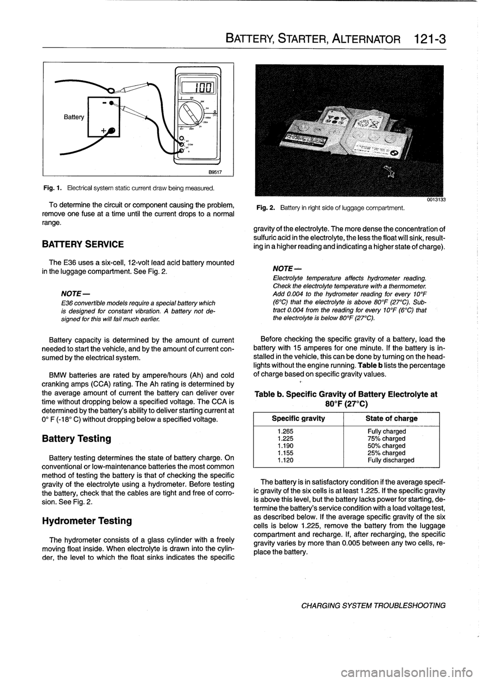
Fig
.1.
Electrical
system
static
current
draw
being
measured
.
To
determine
the
circuit
or
component
causing
the
problem,
remove
one
Puse
at
a
time
until
the
current
drops
to
a
normal
range
.
BATTERY
SERVICE
The
E36
uses
a
six-cell,
12-volt
leadacid
battery
mounted
in
the
luggage
compartment
.
See
Fig
.
2
.
NOTE-
E36
convertible
models
require
a
specialbattery
which
is
designed
for
constant
vibratfon
.
A
battery
not
de-signed
for
this
will
fail
much
earlier
.
Battery
capacity
is
determined
by
the
amount
of
current
needed
tostart
the
vehicle,
and
by
the
amount
of
current
con-
sumed
by
the
electrical
system
.
BMW
batteries
are
rated
by
ampere/hours
(Ah)
and
cold
cranking
amps
(CCA)
rating
.
The
Ah
rating
is
determined
by
the
average
amount
of
current
the
battery
can
deliver
over
time
without
dropping
below
a
specified
voltage
.
The
CCA
is
determined
by
the
battery's
ability
to
deliver
starting
current
at
0°
F
(-18°
C)
without
dropping
below
a
specified
voltage
.
Battery
Testing
noN~A
B9517
Battery
testing
determines
the
state
of
battery
charge
.
On
conventional
or
low-maintenance
batteries
the
most
common
method
of
testing
the
battery
is
that
of
checking
the
specific
gravity
of
the
electrolyte
using
a
hydrometer
.
Before
testing
the
battery,
check
that
the
cables
are
tight
and
free
of
corro-
sion
.
See
Fig
.
2
.
Hydrometer
Testing
The
hydrometer
consists
of
a
glass
cylinder
with
a
freely
moving
float
inside
.
When
electrolyte
is
drawn
into
the
cylin-
der,
the
levelto
which
the
float
sinks
indicates
the
specific
BATTERY,
STARTER,
ALTERNATOR
121-
3
Fig
.
2
.
Battery
in
right
sideof
luggage
compartment
.
gravity
of
the
electrolyte
.
The
more
dense
the
concentration
of
sulfuric
acid
in
the
electrolyte,
the
less
the
float
will
sink,
result-
ing
in
a
higher
reading
and
indicating
a
higher
state
of
charge)
.
NOTE-
Electrolyte
temperature
affects
hydrometer
reading
.
Check
the
electrolyte
temperaturewith
a
thermometer
.
Add
0
.004
to
the
hydrometer
reading
for
every
10°F
(6°C)
that
the
electrolyte
is
above
80°F
(27°C)
.
Sub-
tract
0
.004
from
the
reading
for
every
10°F
(6°C)
that
the
electrolyte
is
below
80°F
(27°C)
.
Before
checking
the
specificgravity
of
a
battery,
load
the
battery
with
15
amperes
for
one
minute
.
lf
the
battery
is
in-
stalled
in
the
vehicle,
this
can
be
done
by
turning
on
the
head-
lights
without
the
engine
running
.
Table
b
lists
the
percentage
of
charge
based
on
specific
gravity
values
.
Table
b
.
Specific
Gravity
of
Battery
Electrolyteat
80
°
F
(27°C)
Specific
gravity
1
Stateof
charge
1
.265
Fully
charged
1
.225
75%
charged
1
.190
50%
charged
1
.155
25%
charged
1
.120
Fully
discharged
The
battery
isin
satisfactory
condition
if
theaverage
specif-
ic
gravity
of
the
six
cells
is
at
least
1
.225
.
If
the
specific
gravity
is
above
this
leve¡,
butthe
battery
lacks
power
for
starting,
de-
termine
the
battery's
senrice
condition
with
a
load
voltage
test,
as
described
below
.
If
the
average
specific
gravity
of
the
six
cells
is
below
1
.225,
remove
the
battery
from
the
luggage
compartment
and
recharge
.
If,
after
recharging,
the
specific
gravity
varies
by
more
than
0
.005
between
any
two
celis,
re-
place
the
battery
.
CHARGING
SYSTEM
TROUBLESHOOTING
Page 143 of 759
Alternator
brushes,
STARTER
SERVICE
inspecting
and
replacing
Regulator
brushesarenot
available
as
replacement
parts
from
BMW
.
Replacement
brushes
may
be
available
from
af-
termarket
sources,
however
.
1
.
Remove
voltage
regulator
as
described
above
.
2
.
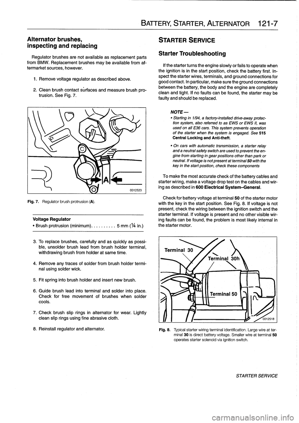
Clean
brush
contact
sürfaces
and
measure
brush
pro-trusion
.
See
Fig
.
7
.
Check
for
battery
voltage
at
terminal
50
of
the
starter
motor
Fig
.
7
.
Regulator
brush
protrusion
(A)
.
with
the
key
in
the
start
position
.
See
Fig
.
8
.
If
voltage
is
not
present,
check
the
wiring
between
the
ignition
switch
and
the
starter
terminal
.
If
voltage
is
present
and
no
other
visible
wir
Voltage
Regulator
ing
faults
can
be
found,
the
problem
is
most
likely
interna¡in
"
Brush
protrusion
(minimum)
.......
.
..
5
mm
(
1
/4
in
.)
the
starter
motor
.
3
.
To
replace
brushes,
carefully
and
as
quickly
as
possi-
ble,
unsolder
brush
lead
from
brush
holder
termina¡,
withdrawing
brush
from
holder
at
same
time
.
4
.
Remove
any
traces
of
solder
frombrush
holder
termi-
nal
using
solder
wick
.
5
.
Fit
spring
into
brush
holder
and
inserí
new
brush
.
6
.
Guide
brush
lead
into
terminal
and
solder
into
place
.
Check
for
free
movement
of
brushes
when
solder
cools
.
7
.
Check
brush
slip
rings
in
alternator
for
wear
.
Lightly
clean
slip
rings
using
fine
abrasive
cloth
.
BATTERY,
STARTER,
ALTERNATOR
121-
7
Starter
Troubleshooting
If
the
starter
tucos
the
engine
slowlyor
fails
to
operate
when
the
ignition
isin
the
start
position,
check
the
battery
first
.
In-
spect
the
starter
wires,
terminals,
and
ground
connections
for
good
contact
.
In
particular,
make
sure
the
ground
connections
between
the
battery,
the
body
and
the
engine
are
completely
clean
and
tight
.
If
no
faults
can
be
found,
the
starter
may
be
faulty
and
should
be
replaced
.
NOTE
-
"
Starting
in1194,
a
factory-installed
drive-away
protec-
tion
system,
alsoreferred
to
as
EWS
or
EWS
11,
was
used
on
all
E36
cars
.
This
system
prevenís
operation
of
the
starter
when
the
system
is
engaged
.
See
515
Central
Locking
and
Anti-theft
.
"
On
cars
with
automatic
transmission,
a
starter
relay
and
a
neutral
safetyswitchare
used
to
present
theen-
ginefrom
starting
in
gear
positions
other
than
park
or
neutral
.
ff
voltage
is
not
present
atterminal
50
with
the
key
in
the
startposition,
check
these
components
To
make
the
most
accurate
check
of
the
battery
cables
and
starterwiring,
make
a
voltage
drop
test
on
the
cables
and
wir-
ing
as
described
in
600
Electrical
System-General
.
Terminal
30
'
\
/
Terminal
30h
0012518
8
.
Reinstall
regulator
and
alternator
.
Fig
.
8
.
Typical
starterwiring
terminal
identification
.
Large
wireat
ter-
minal
30
is
direct
battery
voltage
.
Smaller
wire
at
terminal
50
operates
starter
solenoid
via
ignition
switch
.
STARTER
SERVICE