front susp BMW M3 1993 E36 Workshop Manual
[x] Cancel search | Manufacturer: BMW, Model Year: 1993, Model line: M3, Model: BMW M3 1993 E36Pages: 759
Page 3 of 759
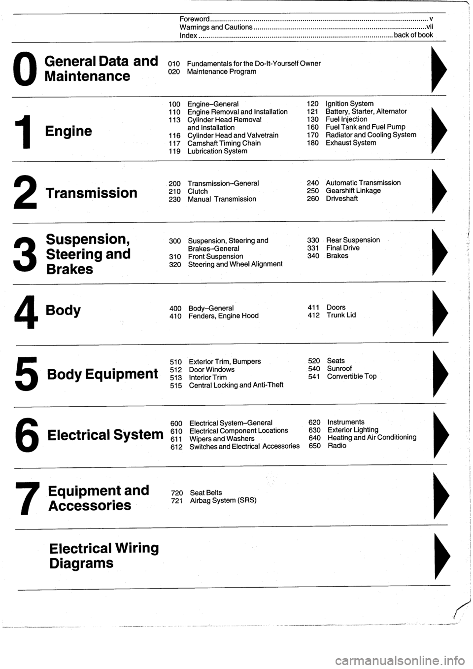
General
Data
and
010
FundamentalsfortheDo-lt-YourselfOwner
Maintenance
020
Maintenance
Program
Engine
Transmission
Suspension,
Steering
and
Brakes
4
Body
100
Engine-General
110
Engine
Removal
and
Installation
113
Cylinder
Head
Removal
and
Installation
116
Cylinder
Head
and
Valvetrain
117
Camshaft
Timing
Chain
119
Lubrication
System
200
Transmission-General
210
Clutch
230
Manual
Transmission
510
Exterior
Trim,
Bumpers
520
Seats
Bo
y
Equipment
512
DoorWTdws
540
nr
t
513
InteriorTrim
541
Convertible
Top
515
Central
Locking
and
Anti-Theft
600
Electrical
System-General
620
Instruments
Electrical
S
stem
610
Electrical
Component
Locations
630
Exterior
Lighting
611
Wipers
and
Washers
640
Heating
and
Air
Conditioning
6
612
Switches
and
Electrical
Accessories
650
Radio
Equipment
and
720
SeatBelts
Accessories
721
Airbag
System
(SRS)
Electrical
Wiring
Diagrams
Foreword
.
...
.
.
.
..................
.
.
.
.....
.
............
.
...
.
.
.
.
.
................
.
.
.
.....
.
......
.
................
.
.
.
.....
v
Warnings
and
Cautions
.....
.
...
.
.
.
.
.
..........
.
...
.
.
.
.
.
......
.
.........
.
.
.
...
.
.
.
......
.
.
.
.
.
............
.
.
.
.
.
.
.vii
Index
..............
.
.
.
.....
.
............
.
...
.
.
.
.
.
........
.
...
.
.
.
.
.
.......
.
......
.
...
.
.
.
.
.
.
.
........
.
.
.
..
back
of
book
300
Suspension,
Steering
and
330
RearSuspension
Brakes-General
331
Final
Drive
310
Front
Suspension
340
Brakes
320
Steering
and
Wheel
Alignment
400
Body-General
411
Doors
410
Fenders,
Engine
Hood
412
Trunk
Lid
120
Ignition
System
121
Battery,Starter,
Alternator
130
Fue¡
Injection
160
Fuel
Tank
and
Fuel
Pump
170
Radiator
and
Cooling
System180
Exhaust
System
240
Automatic
Transmission
250
Gearshift
Linkage
260
Driveshaft
Page 10 of 759

010-2
FUNDAMENTALS
FOR
THE
DO-ITYOURSELF
OWNER
HOW
TO
USE
THIS
MANUAL
A
note
contains
helpfulinformation,
tipsthat
will
hefp
in
The
manual
is
divided
into
ninesections
:
doinga
better
job
and
completing
!t
more
easíly
.
0
GENERAL
DATA
AND
MAINTENANCE
1
ENGINE
2
TRANSMISSION
3
SUSPENSION,
STEERING
AND
BRAKES
4
BODY
5
BODY
EQUIPMENT
6
ELECTRICAL
SYSTEM
7
EQUIPMENTANDACCESSORIES
ELECTRICAL
WIRING
DIAGRAMS
0
GENERAL
DATA
AND
MAINTENANCE
coversthe
rec-
ommended
maintenance
schedules
and
service
procedures
needed
to
perform
BMW
scheduled
maintenance
work
.
Also
within
this
section
is
the
010
Fundamentals
for
the
Do-It-
Yourself
Owner
section,
which
contains
basic
instructions,
tips
and
helpful
hints
for
do-it-yourself
maintenance
and
repair
.
The
next
seven
sections
(1
through
7)
are
repair
based
and
are
further
broken
down
into
three
digit
repair
groups
.
Each
ma-
jor
section
begins
with
a
General
repair
group,
e
.g
.
100En-
gine-General
.
These
"00"
(doublezero)
groups
aremostly
descriptive
in
nature,
covering
topics
suchas
theory
of
opera-
tion
and
troubleshooting
.
The
remainder
of
the
repair
groups
contain
the
more
involved
repair
information
.
The
last
major
section
contains
detailed
electrical
wiring
diagram
schematics
.
A
master
listing
of
the
9major
sections
and
the
correspond-
ing
individual
repair
groups
can
befoundon
the
inside
front
cover
.
Each
repair
group
begins
with
a
Table
of
Contents
listing
the
majos
subject
headings
within
the
group
.
Page
numbers
throughout
the
manual
are
organizedaccording
to
the
repair
groupsystem
.
For
example,
youcan
expect
tofind
repair
infor-
mation
on
brakes
(Repair
Group
340)
beginning
on
page
340-
1
.
A
comprehensive
index
can
be
found
at
the
back
of
the
man-
ual
.
Warnings,
Cautions
and
Notes
Throughout
this
manualare
many
passages
with
the
head-
ings
WARNING,
CAUTION,
or
NOTE
.
These
very
important
headings
have
diflerent
meanings
.
WARNING
-
The
text
under
this
heading
warns
of
unsafe
practic-
es
thatare
very
likelyto
cause
ínjury,
eitherby
dírect
threat
to
the
person(s)
pertorming
the
work
or
by
in-
creased
risk
of
accident
or
mechanfcal
fallure
whíle
driving
.
CAUTION-
A
caution
calls
attention
to
important
precautions
to
beobserved
during
the
repair
work
that
will
helo
prevent
accidentally
damaging
the
caror
its
parts
.
GETTING
STARTED
Safety
NOTE-
Please
read
every
WARNING,
CAUTION,
and
NOTE
at
the
front
of
the
manual
and
as
they
appear
in
repair
procedures
.
They
are
very
important
.
Read
them
before
you
begin
any
maintenance
or
repair
job
.
Some
WARNINGs
and
CAUTIONs
are
repeated
wherever
they
apply
.
Read
them
all
.
Do
not
skip
any
.
These
messages
are
important,
even
to
the
owner
who
never
intends
to
workon
thecar
.
GETTING
STARTED
Most
of
the
necessary
maintenance
and
minor
repair
that
an
automobile
will
need
canbe
done
with
ordinary
tools,
evenby
owners
with
little
or
no
experience
in
car
repair
.
Below
is
some
important
information
on
how
to
work
safely,
a
discussion
of
what
tools
will
be
needed
and
how
to
use
them
.
Although
an
automobile
presents
many
hazards,
common
sense
and
good
equipment
can
helo
ensure
safety
.
Many
acci-
dents
happen
because
of
carelessness
.
Pay
attention
and
stick
to
these
few
important
safety
rules
.
WARNING
-
"
Never
run
the
engine
in
the
work
area
unless
it
is
well-ventflated
.
Theexhaustshouldbe
vented
to
the
outside
.
Carbon
monoxide
(CO)
in
theex-
haust
kilts
.
"
Remove
all
neckties,
scarts,
loose
clothing,
or
jewelry
when
working
near
running
engines
or
power
tools
.
Tuck
in
shirts
.
Tie
long
haír
and
se-
cure
it
under
a
cap
.
Severe
injury
can
result
from
these
things
beíngcaught
in
rotating
parts
.
"
Remove
ríngs,
watches,
and
bracelets
.
Asíde
from
the
dangersof
moving
parts,
metallic
jew-
elry
conducts
electricity
and
may
cause
shorts,
sparks,
bums,
or
damage
to
the
electrical
sys-
tem
when
accidentally
contacting
the
battery
or
other
electrical
terminals
.
"
Disconnect
the
battery
negative
()
cable
when-
ever
working
on
ornear
the
fuel
system
or
any-
thlng
that
is
electrically
powered
.
Accidental
electrícal
contact
may
damage
the
electrical
system
or
cause
a
fire
.
Page 20 of 759
010-12
FUNDAMENTALSFOR
THE
DO-IT
YOURSELF
OWNER
Jump
Starting
Car
Cars
with
discharged
or
dead
batteries
can
be
jump-started
using
the
good
battery
from
another
car
.
When
jump-starting
the
engine,
always
note
the
following
warnings
.
WARNING
-
"
Battery
acid
(electrolyte)
can
cause
severe
burns,
and
will
damage
the
car
and
clothing
.
lf
electrolyte
is
spilled,
wash
the
surface
with
large
quantities
of
water
.
lfit
gets
finto
eyes,
flush
them
with
water
for
severa¡
minutes
and
cal¡
a
doctor
.
"
Batteries
produce
explosive
and
noxious
gas-
ses
.
Keep
sparks
and
flames
away
.
Do
not
smoke
near
batteries
.
"
Do
not
jump-start
the
engine
if
you
suspect
that
the
battery
is
frozen
.
Trapped
gas
may
explode
.
Allow
the
battery
to
thaw
first
.
"
Do
not
quick-charge
the
battery
(for
boost
start-
ing)for
longer
than
one
minute,
and
donot
ex-
ceed
15
volts
at
the
battery
with
the
boosting
cables
attached
.
Wait
at
least
one
minutebefore
boosting
the
battery
a
second
time
.
"
Some
electrical
system
'comfort"
features
may
not
function
correctly
once
battery
power
is
restored
.
For
example,
the
front
window
one-touch-up
func-
tion
may
be
disabled
.
Some
electrical
systems
will
need
to
be
reinitialized
Consult
the
appropriate
re-
pairgroup
formore
specific
information
.
1
.
Place
cars
close
together,
but
do
not
allow
them
to'touch
each
other
.
Turn
off
the
engine
of
thecar
with
the
good
battery
.
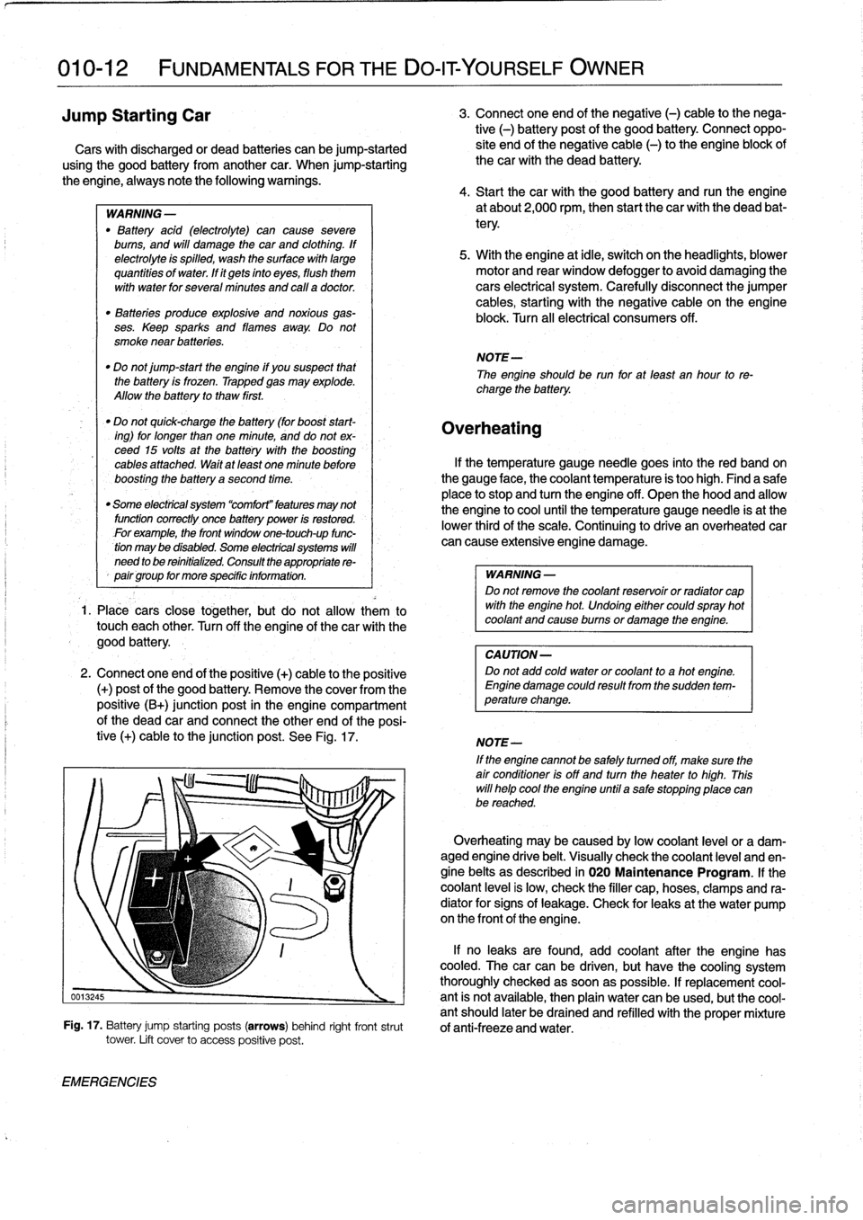
2
.
Connect
oneend
of
the
positive
(+)
cable
to
the
positive
(+)
post
of
the
good
battery
.
Remove
the
coverfromthe
positive
(B+)
junction
post
in
the
engine
compartment
of
the
dead
car
and
connect
the
other
end
of
the
posi-
tive
(+)
cable
to
the
junction
post
.
See
Fig
.
17
.
EMERGENCIES
3
.
Connect
one
end
of
the
negative
(-)
cable
to
the
nega-
tive
(-)
battery
post
of
the
good
battery
.
Connect
oppo-
site
end
of
the
negative
cable
(-)
to
the
engine
block
of
thecar
with
the
dead
battery
.
4
.
Start
thecar
with
the
good
battery
and
runthe
engine
at
about2,000
rpm,
then
start
the
car
with
the
dead
bat-
tery
.
5
.
With
the
engine
at
¡dle,
switch
on
the
headlights,
blower
motor
and
rear
window
defogger
to
avoid
damaging
the
cars
electrical
system
.
Carefully
disconnect
the
jumper
cables,
starting
with
the
negative
cable
on
the
engine
block
.
Turn
all
electrical
consumers
off
.
NOTE-
The
engineshould
be
run
for
at
least
an
hour
to
re-
charge
the
battery
.
Overheating
lf
the
temperature
gauge
needle
goes
into
the
red
band
on
the
gauge
face,
the
coolant
temperature
is
too
high
.
Find
a
safe
place
to
stop
and
turn
the
engine
off
.
Open
the
hood
and
allow
the
engine
to
cool
until
the
temperature
gauge
needle
is
at
the
lower
thirdof
the
scale
.
Continuing
to
drive
an
overheated
car
can
cause
extensive
engine
damage
.
WARNING
-
Do
not
remove
the
coolant
reservoir
or
radíator
cap
with
the
engine
hot
.
Undoing
either
couldspray
hot
coolant
and
cause
burns
or
damage
the
engine
.
CAUTION-
Do
not
add
cold
water
or
coolant
to
a
hot
engine
.
Engine
damage
could
result
from
the
sudden
tem-
perature
change
.
NOTE-
If
the
enginecannot
be
safely
tumed
off,
make
sure
the
air
condifioner
isoff
and
turn
the
heater
to
high
.
This
will
helo
cool
the
engine
until
a
salestopping
place
canbe
reached
.
Overheating
may
be
caused
bylow
coolant
leve¡
or
a
dam-aged
engine
drive
belt
.
Visually
check
the
coolant
leve¡
and
en-
gine
belts
as
described
in
020
Maintenance
Program
.
lf
the
coolant
leve¡
is
low,
check
the
filler
cap,hoses,
clamps
and
ra-
diator
for
signs
of
leakage
.
Check
for
leaks
at
the
water
pump
on
the
frontof
theengine
.
lf
no
leaks
are
found,
add
coolant
after
the
engine
has
cooled
.
The
carcan
be
driven,
but
have
the
cooling
system
thoroughly
checked
assoonas
possible
.
lf
replacement
cool
0013245
-
ant
is
not
available,
then
plain
water
canbe
used,
butthe
cool-
antshould
later
be
drained
and
refilled
with
theproper
mixture
Fig
.
17
.
Battery
jump
starting
posts
(arrows)
behind
right
frontstrut
of
anti-freeze
and
water
.
tower
.
Lift
cover
to
access
positive
post
.
Page 23 of 759
020
Maintenance
Program
GENERAL
.
.
...
.
.
.
...
.
.
.
.
.
.
.
.
.
.
.
...
.
..
020-2
BMW
Service
Indicator
......
..
....
..
...
..
.
020-2
Oil
Service
.....
.
..........
..
...
...
...
..
.
020-2
Inspection
I
and
Inspection
II
.
..
....
..
...
..
.
020-2
Resetting
Service
Indicator
....
.
....
..
...
..
.
020-3
MAINTENANCE
TABLES
..
.
.
.
.
.
........
020-3
FLUID
AND
LUBRICANT
SPECIFICATIONS
.
.
.
.
.
.
.
...
.
.
.
....
.
...
020-8
Manual
Transmission
Fluid
..
.
.
.
.
.
....
.
.
.
.
020-8
Automatic
Transmission
Fluid
.
.
.
.
.
....
.
.
.
.
020-8
Final
Drive
Gear
Oil
................
.
.
.
.
020-9
Brake
Fluid
.
.
.
.
.
................
.
.
.
.
020-9
Engine
Coolant
(Anti-freeze)
.
.
...
.
....
.
.
.
.
020-9
Power
Steering
Fluid
........
..
......
.
.
.
.
020-9
ENGINE
OIL
SERVICE
.
.
...
.
.
.
...
.
.
.
.
.
.
020-9
Engine
oil,
checking
leve¡
..
...
...
..
........
020-9
Engine
oil
and
filter,
changing
....
.
......
.
..
020-9
ENGINE
COMPARTMENT
MAINTENANCE
...
.
.
.
.
.
.
.
.
.
.
.
.
.
......
020-10
Air
filter,
replacing
.
...
...
.
.....
.
.....
.
...
020-11
Spark
plugs,
replacing
...
.
......
.
...
..
...
020-11
¡dle
Speed
.
..
...
...
....
.
......
.
...
..
...
020-12
Battery,
checking
and
cleaning
.......
..
...
020-12
Battery,
replacing
.
.....
.
.....
.
.....
..
...
020-12
Accelerator
and
Throttle
Linkage
.
.....
..
...
020-13
Engine
DriveBelts
.....
.
....
..
...
...
...
.
020-13
V-belt,
replacing
(4-cylinder
engines
built
up
to
1/94)
..
....
.
020-13
Poly-ribbed
belt,
replacing
(4-cylinder
engines
built
from
1194
and
all
6-cylinder
engines)
.
.
....
..
......
020-13
Cooling
System
Service
.
...
..
....
..
....
..
020-14
Power
steering
fluid,
checking
leve¡
.
..
....
.
.
020-14
Oxygen
Sensors
....
...
..
..
....
.
.....
.
.
020-15
MAINTENANCE
PROGRAM
020-1
UNDER-CAR
MAINTENANCE
.
..
.
...
.
.
.020-16
'
Fuel
filter,
replacing
...
.
.....
..
.....
..
..
.020-16
Tires,
checking
inflation
pressure
.
.....
.
....
020-17
Tires,
rotating
...
..
.....
..
....
..
....
.
....
020-17
Wheels,
aligning
..
.....
.
...........
.
....
'020-17
Brake
system,
inspecting
.
.
....
.
.....
..
...
020-17
Brake
pad/rotor
wear,checking
.
......
.
....
020-17
Brake
fluid,
replacing
.........
..
.
..
..
.
020-17
Parking
brake,
checking
......
.
.....
..
....
020-17
Exhaust
system,
inspecting
....
..
.....
.
...
.020-18
Manual
Transmission
Senrice
..
..
.....
.
....
020-18
Manual
transmission
fluida
checking
and
filling
..
.
....
..
.
.
..
..
....
020-18
AutomaticTransmission
Service
.
....
...
....
020-18
Front
suspension
and
steeringlinkages,
inspecting
..
.
:.....
.
....
..
.....
..
...
.
.020-18
Rear
suspension,
inspecting
.
..
...
...
....
..
020-18
Final
drive
oil
leve¡,
checking
.
.
.
...
....
...
..
020-18
Fuel
tank
and
fuel
lines,
inspecting
.
.....
....
020-19
Clutch
fluid,
checking
...
...
...
...
....
.....
020-19
Drive
axle
joint
boots,
inspecting
...
..
.....
..
020-19
BODY
AND
INTERIOR
MAINTENANCE
.
.
.
.
.
.
.
.
.
.
.
.
.
.
.
.
.
.
...
.
.020-19
Windshield
Wiper
Blade
Maintenance
....
.
.
020-19
Body
and
hinges,
lubricating
.
.....
..
......
.
020-19
Seat
Belts
...
..
...
...
...
..
.....
..
.....
.
.
020-20
Exterior
Washing
..
...
...
..
.
.
...
..
......
.020-20
Waxing
.....
..
...
...
...
..
.....
..
.......
020-20
Polishing
..
...
...
...
....
..
..........
..
.
.'020-20
Washing
Chassis
.
...
....
.
....
..
.....
.
...
020-20
Special
Cleaning
.
.
.....
..
...
.
.....
..
..
.020-20
Interior
Care
.
....
..
....
..
..
.
.
......
.
...
020-20
Leather
Upholstery
and
Trim
...
..
....
...
...
020-20
TABLES
a
.
Oil
Service
......
...
.
..
.............
...
---
020-4
b
.
Inspection
1
Service
..
.
.
.............
....
...
020-5
c
.
Inspection
11
Service
.
.
...
...........
..
.
..
..
020-6
d
.
Scheduled
Maintenance-Time/Mileage
Intervals
..
020-7
e
.
Fluids
and
Lubricants
..
...
...........
.....
..
020-8
Page 27 of 759
Table
b
.
Inspection
I
Service
MAINTENANCE
PROGRAM
020-5
ad
d
d
ID
a
r
c
d
a~
;v
a
:
Q~
wE
y
a
r
E
R
:
L-
0
Maintenance
ítem
1
z
3
~
c
d
Engine
compartment
maintenance
Change
oil
and
oil
filter
.
Check
brake/clutch
fluid
leve¡
Check
battery
acid
leve¡
and
correct
asnecessary
.
Repair
Group
121
Check
engine
coolant
level
and
anti-freeze
protection
and
addasnecessary
.
Inspect
for
cooling
system
leaks
.
Repair
Group
170
Lubricate
throttie
linkage
Under
car
maintenance
Check
transmission
for
externa¡
leaks
.
Check
manual
transmission
oil
leve¡
andadd
asnecessary
.
Repair
Group
230
Check
final
drive
lubricant
and
addasnecessary
.
Check
fue¡
tank,
fuel
lines,
and
all
connections
for
leaks
.
Inspect
exhaust
system
.
Repair
Group
180
Check
steeringrack
and
steeringlinkages
.
Check
power
steering
system
for
leaks
.
Check
(luid
leve¡
.
Repair
Group
320
Inspect
brake
system
for
damaged
hoses
and
fines,
leaks
or
damage
.
Remove
calipers
and
check
brake
pad
wear
.
Check
brake
rotors
for
scoring
damage
.
Repair
Group
340
Check
parking
brake
operation,
adjust
cable
if
necessary
Repair
Group
340
Inspect
front
and
rear
suspension,
including
wheel
bearings,
for
play
.
Repair
Group
320/330
Inspect
wheelsand
tires,
including
spare,
check
tire
pressure
and
condition
Body
and
Interior
Maintenance
Lubricate
door
hinges
and
hood
latch,
hood
hinges
Check
headlight
and
driving
light
aiming
and
adjust
as
necessary
.
Check
operation
of
headlights,
parking
lights,
back-up
fights,
licenseplate
lights,
interior
lights,
glove
box
light,
engine
compartment
light,
trunk
light,
instrument
panel
lights,
turnsignals,
emer-gency
flashers,
stop
fights,
horas,
headlight
flasher
and
dimmer
switch
Replace
ventilation/A/C
micro-filter
.
Check
functionof
air
conditioning
.
Repair
Group
640
Check
function
of
seat
belts
.
Repair
Group
720
Check
tightness
of
mountfng
screws
on
airbag
front
crash
sensors
(Airbag
I)
.
Repair
Group
721
Check
windshield
washer
fluid
leve¡
and
concentration,
add
as
necessary
Check
operation
of
washer
system
.
Check
condition
of
wiperblades
.
Repair
Group
611
Tighten
nuts
and
bolts
for
door
locks
and
striker
plates
Replace
batteries
for
alarm/remote
control
in
masterkey(where
applicable)
.
Road
Test
Check
braking
performance,
steering,
HVAC,
manual
or
automatic
transmission,
and
mirrors
Service
Interval
Reset
Reset
service
indicator
using
specialreset
tool
.
MAINTENANCE
TALES
Page 28 of 759
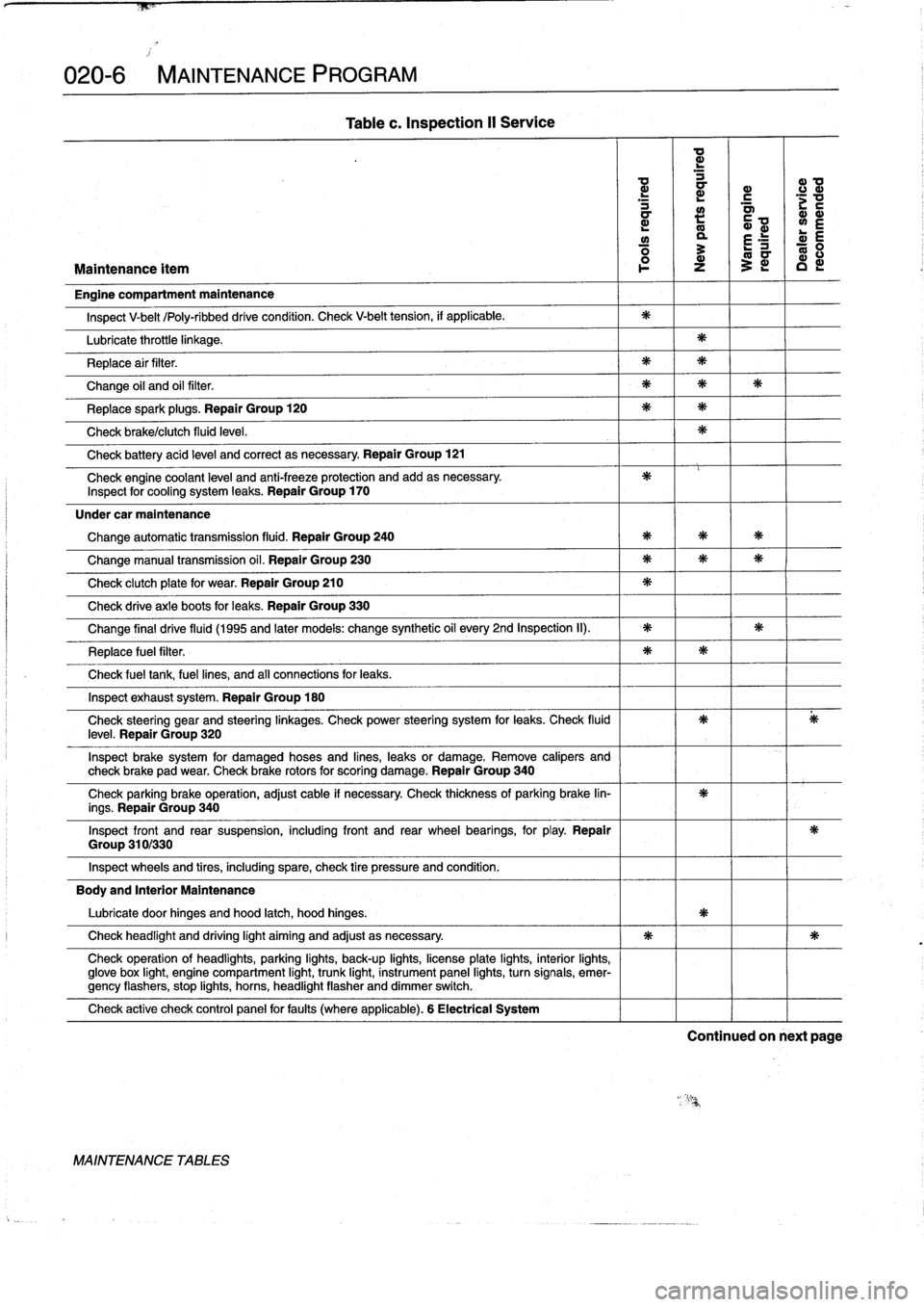
020-6
MAINTENANCE
PROGRAM
Group
310/330
Table
c
.
Inspection
II
Service
a
d
d
a
a>
0
d
a
r
.c
mm
L
m
y
L
E
ó
3
E
ó
Maintenance
ítem
l
o-
z
~
c
Engine
compartment
maintenance
Inspect
V-belt
/Poly-ribbeddrive
condition
.
Check
V-belt
tension,
if
applicable
.
Lubricate
throttle
linkage
.
Replace
air
filter
.
Change
oil
and
oil
filter
.
Replacespark
plugs
.
Repair
Group
120
Check
brake/clutch
fluid
leve¡
.
Check
battery
acid
leve¡
and
correct
asnecessary
.
Repair
Group
121
Check
engine
coolant
leve¡
and
anti-freeze
protection
and
add
asnecessary
.
Inspect
for
cooling
system
leaks
.
Repair
Group
170
Under
car
maintenance
Change
automatic
transmission
fluid
.
Repair
Group
240
Change
manual
transmission
oil
.
Repair
Group
230
Check
clutch
plate
for
wear
.
Repair
Group
210
Check
drive
axle
boots
for
leaks
.
Repair
Group
330
Change
final
drive
fluid
(1995
and
later
models
:
change
synthetic
oil
every
2nd
Inspection
II)
.
Replace
fuel
filter
.
Check
fuel
tank,
fuel
lines,
and
af
connections
for
leaks
.
Inspect
exhaust
system
.
Repair
Group
180
Check
steering
gear
and
steering
¡inkages
.
Check
power
steering
system
for
leaks
.
Check
fluidleve¡
.
Repair
Group
320
Inspect
brake
system
for
damaged
hoses
and
lines,
leaks
or
damage
.
Remove
calipers
and
check
brake
pad
wear
.
Check
brake
rotors
for
scoring
damage
.
Repair
Group
340
Check
parking
brake
operation,
adjust
cable
if
necessary
.
Check
thickness
of
parking
brake
lin-
ings
.
Repair
Group
340
Inspect
front
and
rear
suspension,
including
front
and
rear
wheel
bearings,
for
play
.
Repair
Inspect
wheels
and
tires,
including
spare,
check
tire
pressure
and
condition
.
Body
and
Interior
Maintenance
Lubricate
door
hinges
and
hood
latch,
hood
hinges
.
Check
headlight
and
driving
light
aiming
and
adjust
asnecessary
.
Check
operation
of
headlights,
parking
lights,
back-up
lights,
licenseplate
lights,
interior
lights,
glove
box
light,
engine
compartment
light,
trunk
light,
instrument
panel
lights,
turn
signals,
emer-gency
flashers,
stop
lights,
horns,
headlight
flasher
anddimmer
switch
.
Check
active
check
control
panel
forfauits
(where
applicable)
.
6
Electrical
System
MAINTENANCE
TABLES
Continued
on
next
page
Page 39 of 759
Tires,
checking
inflation
pressure
Brake
pad/rotor
wear,
checking
Correct
tire
pressuresare
important
to
handling
and
stability,
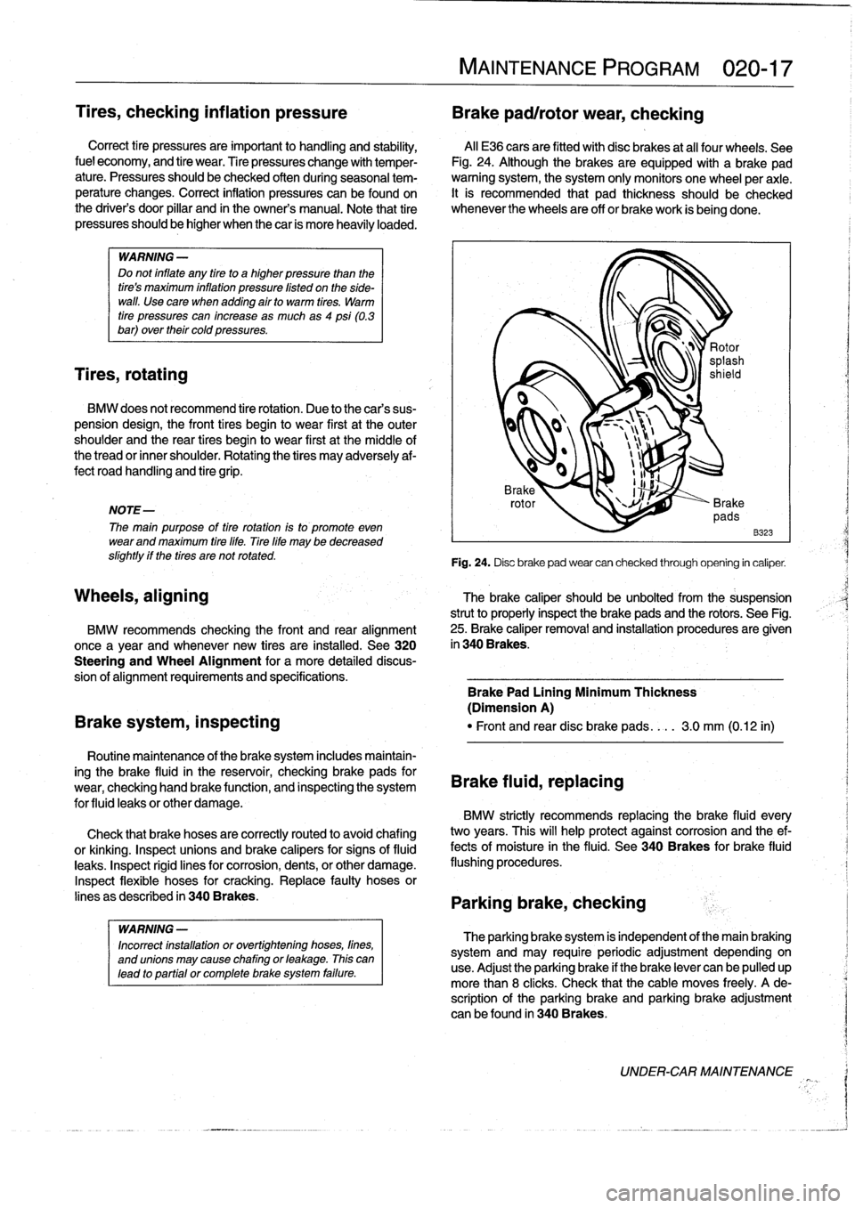
Al¡
E36
cars
are
fitted
withdisc
brakes
at
al¡
four
wheels
.
See
fuel
economy,
and
tire
wear
.
Tire
pressures
change
with
temper-
Fig
.
24
.
Although
thebrakesare
equipped
with
a
brake
pad
ature
.
Pressures
should
be
checked
often
during
seasonal
tem-
warning
system,
the
system
only
monitors
one
wheel
per
axle
.
perature
changes
.
Correct
inflation
pressures
canbe
found
on
It
is
recommended
that
pad
thickness
should
be
checked
the
driver's
door
pillar
and
in
the
owner's
manual
.
Note
that
tire
whenever
the
wheels
are
off
or
brakework
is
beggg
done
.
pressuresshould
be
higher
when
thecar
is
more
heavily
loaded
.
WARNING
-
Do
not
inflate
any
tire
to
a
higher
pressure
than
the
tiress
maximum
ínflation
pressure
listed
on
the
side-
wall
.
Use
cara
when
addlng
air
to
warm
tires
.
Warm
tire
pressures
can
increase
as
much
as4
psi
(0.3
bar)
over
their
cold
pressures
.
Tires,
rotating
BMW
does
not
recommend
tire
rotation
.
Due
to
the
cars
sus-
pension
design,
the
fronttires
begin
to
wear
first
at
the
outer
shoulder
and
the
rear
tires
begin
to
wear
first
at
themiddle
of
the
tread
or
inner
shoulder
.
Rotating
the
tires
may
adversely
af-
fect
roadhandling
and
tire
grip
.
NOTE-
The
main
purpose
of
tire
rotation
isto
promote
even
wear
and
maximum
tire
life
.
Tire
life
may
be
decreased
slightly
if
the
tires
are
not
rotated
.
Wheels,
aligning
Routine
maintenance
of
the
brake
system
includes
maintain-
ing
the
brake
fluid
in
the
reservoir,
checking
brakepads
for
wear,
checking
hand
brake
functíon,
and
inspecting
the
system
for
fluid
leaks
or
other
damage
.
Check
that
brake
hoses
are
correctly
routed
to
avoidchafing
or
kinkíng
.
Inspect
unions
and
brake
calipers
for
signs
of
fluid
leaks
.
Inspect
rigid
fines
for
corrosion,
dents,
or
other
damage
.
Inspect
flexible
hoses
for
cracking
.
Replace
faulty
hoses
or
lines
as
described
in
340Brakes
.
WARNING
-
Incorrect
installation
or
overtightening
hoses,
fines,
and
unions
may
cause
chafing
or
leakage
.
This
can
lead
to
partíal
or
completebrake
system
failure
.
MAINTENANCE
PROGRAM
020-
1
7
B323
Fig
.
24
.
Disc
brake
pad
wear
can
checked
through
opening
in
caliper
.
The
brake
caliper
should
be
unbolted
from
the
suspension
strut
to
properly
inspect
the
brake
pads
and
the
rotors
.
See
Fig
.
25
.
Brake
caliper
removal
and
installation
procedures
are
given
in
340
Brakes
.
BMW
recommends
checking
the
front
and
rear
alignment
once
a
year
and
whenever
new
tires
are
installed
.
See320
Steering
and
Wheel
Alignment
for
a
more
detailed
discus-
sion
of
alignment
requirements
and
specifications
.
Brake
Pad
Lining
Minimum
Thickness
(Dimension
A)
Brake
system,
inspecting
"
Front
and
reardisc
brake
pads
....
3
.0
mm
(0
.12
in)
Brake
fluid,
replacing
BMW
strictly
recommends
replacing
the
brake
fluid
every
two
years
.
This
will
help
protect
against
corrosion
and
the
ef-
fects
of
moisture
in
the
(luid
.
See340
Brakes
for
brake
fluid
flushing
procedures
.
Parking
brake,
checking
The
parking
brakesystem
is
independent
of
the
main
braking
system
and
may
requireperiodic
adjustment
dependingon
use
.
Adjust
the
parking
brake
if
the
brake
lever
can
be
pulled
up
more
than
8
clicks
.
Check
that
the
cable
moves
freely
.
A
de-
scription
of
the
parking
brake
and
parking
brake
adjustment
can
be
found
in
340Brakes
.
UNDER-CARMAINTENANCE
Page 40 of 759
020-
1
8
MAINTENANCE
PROGRAM
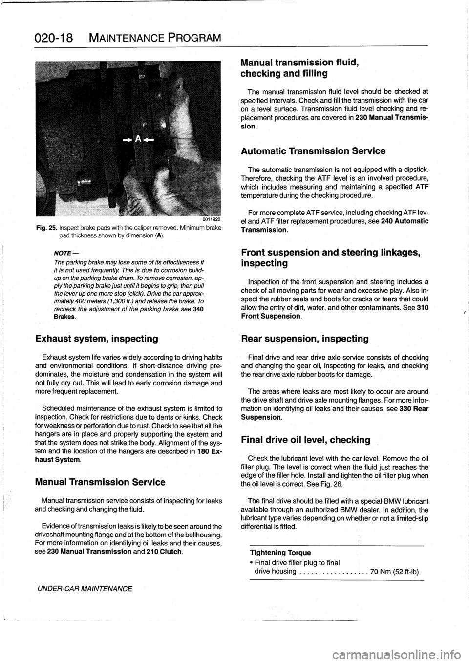
Fig
.
25
.
Inspect
brake
pads
with
the
caliper
removed
.
Minimum
brake
pad
thickness
shown
by
dimension
(A)
.
NOTE-
The
parking
brake
may
lose
some
of
its
effectiveness
if
it
is
not
used
frequently
.
This
is
due
to
corrosion
build-
up
on
the
parking
brake
drum
.
To
remove
corrosion,
ap-
plythe
parking
brake
just
until
it
begins
togrip,
then
pulí
the
lever
up
one
more
stop
(click)
.
Drive
thecar
approx-
imately
400
meters
(1,300
ft
.)
and
release
the
brake
.
To
recheck
the
adjustment
of
the
parking
brake
see340
Brakes
.
UNDER-CAR
MAINTENANCE
0011920
Manual
transmission
fluid,
checking
and
filling
The
manual
transmission
fluid
leve¡
should
be
checked
at
specified
intervals
.
Check
and
fill
the
transmission
with
the
car
ona
leve¡
surface
.
Transmission
(luid
leve¡
checking
and
re-
placement
procedures
are
covered
in
230
Manual
Transmis-
sion
.
Automatic
Transmission
Service
The
automatic
transmission
is
not
equipped
with
a
dipstíck
.
Therefore,
checking
the
ATF
level
is
an
ínvolved
procedure,
which
includes
measuring
and
maintaining
a
specified
ATF
temperature
during
the
checking
procedure
.
For
more
complete
ATF
service,
including
checking
ATF
lev-
e¡
and
ATF
filter
replacement
procedures,
see
240
Automatic
Transmission
.
Front
suspension
and
steering
linkages,
inspecting
Inspection
of
the
front
suspension'and
steering
includes
a
check
of
all
moving
parts
for
wear
and
excessive
play
.
Also
in-
spect
the
rubber
seals
and
boots
for
cracks
or
tears
that
could
allow
the
entry
of
dirt,
water,
and
other
contaminants
.
See
310
Front
Suspension
.
Exhaust
system,
inspecting
Rear
suspension,
inspecting
Exhaust
system
life
varies
widely
according
to
driving
habits
Final
drive
and
rear
drive
axle
service
consists
of
checking
and
environmental
conditions
.
If
short-distance
driving
pre-
and
changing
the
gear
oil,
inspecting
for
leaks,
and
checking
dominates,
the
moisture
and
condensation
in
the
system
will
the
rear
drive
axle
rubber
boots
for
damage
.
not
fully
dryout
.
This
will
lead
to
early
corrosion
damage
and
more
frequent
replacement
.
The
areas
where
leaks
are
most
likely
to
occur
are
around
the
driveshaft
and
drive
axle
mounting
flanges
.
For
more
infor
Scheduled
maintenance
of
the
exhaust
system
is
limitedlo
mation
on
ídentifying
oil
leaks
and
their
causes,
see330
Rear
inspection
.
Check
for
restrictions
due
to
dents
or
kinks
.
Check
Suspension
.
for
weakness
or
perforation
due
to
rust
.
Check
lo
see
that
all
the
hangers
are
in
place
and
properly
supporting
the
system
and
that
the
system
does
not
strike
the
body
.
Alignment
of
the
sys-
Final
drive
oil
leve¡,
checking
temand
the
location
of
the
hangers
aredescribed
in
180
Ex-
haust
System
.
Check
the
lubricant
leve¡
with
thecar
level
.
Remove
the
oil
filler
plug
.
The
leve¡
is
correct
when
the
fluidjust
reaches
the
edge
of
the
filler
hole
.
Install
and
tighten
the
oil
filler
plug
when
Manual
Transmission
Service
the
oil
level
is
correct
.
See
Fig
.
26
.
Manual
transmissionservice
consists
of
inspectingfor
leaks
The
final
drive
should
be
filled
with
a
special
BMW
lubricant
and
checking
and
changing
the
fluid
.
available
through
an
authorized
BMW
dealer
.
In
addition,
the
lubricant
type
varies
depending
onwhether
or
nota
limited-slip
Evidence
of
transmissionleaks
is
fkely
to
beseenaround
the
differential
is
fitted
.
driveshaft
mounting
flange
and
at
the
bottom
of
the
bellhousing
.
For
more
information
on
identifying
oil
leaks
and
their
causes,
see230ManualTransmissionand210
Clutch
.
Tightening
Torque
"
Finaldrive
filler
plug
to
final
drive
housing
..................
70
Nm
(52
ft-Ib)
Page 56 of 759
100-
1
4
ENGINE-GENERAL
0013131
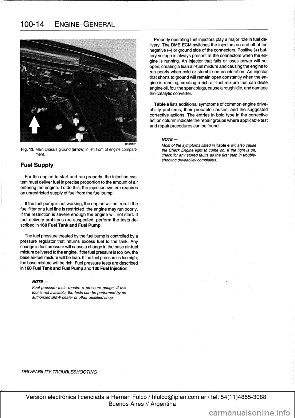
Fig
.
13
.
Main
chassis
ground
(arrow)
inleft
front
of
engine
compart-
ment
.
Fuel
Supply
For
the
engine
tostart
and
run
properly,
the
injection
sys-
tem
must
deliver
fuel
in
precise
proportion
to
the
amount
of
air
entering
the
engine
.
Todo
this,
the
injection
system
requires
an
unrestricted
supply
of
fuel
from
the
fuel
pump
.
If
the
fuel
pump
is
not
working,
the
engine
will
notrun
.
If
the
fuel
filter
or
a
fuel
line
is
restricted,
the
engine
may
run
poorly
.
If
the
restriction
is
severe
enough
the
engine
will
not
start
.
lf
fuel
delivery
problemsare
suspected,
perform
the
tests
de-
scribed
in
160
Fuel
Tank
and
Fuel
Pump
.
The
fuel
pressure
created
by
the
fuel
pump
is
controlled
by
a
pressure
regulator
thatreturns
excess
fuelto
the
tank
.
Any
change
in
fuel
pressure
will
cause
a
change
in
the
base
air-fuel
mixture
delivered
to
the
engine
.
If
the
fuel
pressure
is
too
low,
the
base
air-fuel
mixture
will
be
lean
.
lf
the
fuel
pressure
is
too
high,
the
base
mixture
will
be
rich
.
Fuel
pressure
tests
aredescribed
in
160
Fuel
Tank
and
Fuel
Pump
and130
Fuel
Injection
.
NOTE-
Fuel
pressure
tests
require
a
pressure
gauge
.
If
thistoolís
not
avaílable,
the
tests
can
be
performed
byan
authorized
BMW
dealer
or
other
qualified
shop
.
DRIVEABILITY
TROUBLESHOOTING
Properly
operating
fuel
injectors
play
amajor
role
in
fuel
de-
livery
.
The
DMEECM
switches
the
injectors
on
and
off
at
the
negative
(-)
or
ground
side
of
the
connectors
.
Posítíve
(+)
bat-
tery
voltage
is
always
present
at
the
connectors
when
theen-
gine
is
running
.
An
injector
that
fails
or
loses
power
will
not
open,
creating
a
lean
air-fuel
mixture
and
causing
the
engine
to
run
poorly
when
coldor
stumble
on
acceleration
.
An
injector
that
shorts
to
ground
will
remain
open
constantly
when
the
en-
gine
is
running,
creating
a
richair-fuel
mixture
that
can
dilute
engine
oil,
foul
the
spark
plugs,
cause
a
rough
idle,
and
damage
the
catalytic
converter
.
Table
e
lists
additional
symptoms
of
common
engine
drive-
ability
problems,
their
probable
causes,
and
the
suggested
corrective
actions
.
The
entries
in
boldtype
in
the
corrective
action
column
indicate
the
repair
groups
where
applicable
test
and
repair
procedures
can
befound
.
NOTE-
Most
of
the
symptoms
fisted
in
Table
e
will
also
cause
the
Check
Engine
light
to
come
on
.
If
the
light
is
on,
check
for
any
stored
faults
as
the
first
step
ín
trouble-
shooting
driveability
complaints
.
Page 67 of 759
113
Cylinder
Head
Removal
and
Installation
GENERAL
.
...............
.
.
.
.
.
.......
113-1
CYLINDER
HEAD,
6-CYLINDER
.
.
.
.
.
.
.
113-10
Cylinder
head,
removing
(6-cylinder
engine)
..
113-10
CYLINDER
HEAD,
4-CYLINDER
..
.
...
.
.
113-1
Cylinder
head,
installing
(6-cylinder
engine)
...
113-15
Cylinder
head,
removing
(4-cylinder
engine)
...
113-1
E
Cylinder
head,
installing
(4-cylinder
engine)
...
113-6
GENERAL
CYLINDER
HEAD,
4-CYLINDER
The
information
given
inthis
repair
group
assumes
that
the
engine
is
installed
in
the
engine
bay
.
For
cylinder
head,
cam-
Cylinder
head,
removing
shaft,
and
valvetrain
disassembly
and
reconditioning
informa-
(4-cylinder
engine)
tion,
see116
Cylinder
Head
and
Valvetrain
.
For
ease
of
use
this
removal
procedure
is
broken
into
sub-
In
the
procedures
given
below,
engines
are
referred
to
by
sections,
as
follows
:
engine
code
.
If
necessary,
see100
Engine-General
for
en-
gine
code
and
application
information
.
NOTE-
If
a
head
gasket
problem
is
suspected,
acompression
test
will
usually
detectthe
fault
.
See
100
Engine-Gen-
eral
for
compression
testing
information
.
Special
BMW
service
tools
are
required
to
properly
remove
and
install
the
cylinder
head
on
both
the
4-cylinder
and
6-cyl-
inder
engines
.
The
special
tools
are
used
to
time
the
val-
vetrain
to
the
crankshaft
and
to
remove
the
Torx
(El
2)
head
bolts
.
Read
the
procedure
through
before
beginning
thejob
.
Cover
al¡
painted
surfaces
before
beginning
the
removal
procedure
.
As
an
aid
to
installation,
label
all
components,
wires,
and
hoses
before
removing
them
.
Do
not
reuse
gas-
kets,
O-rings
or
seals
during
reassembly
.
WARNING
-
Due
to
risk
of
personal
injury,
be
sure
the
engine
is
cold
before
beginning
the
removalprocedure
.
CYLINDER
HEAD
REMOVAL
AND
INSTALLATION
113-1
General
Coolingsystem,
draining
Cylinder
head
cover,
removing
Intake
manifold,
removing
Timing
chains,
uncoupling
Cylinder
head
assembly,
removing
WARNING
-
Allow
engine
to
cool
before
beginning
this
proce-
dure
.
General
1
.
Disconnect
negative
(-)
cable
from
battery
.
CAUTION
-
"
Prior
to
disconnectiog
the
battery,
read
the
bat-
tery
disconnection
cautions
given
at
the
front
of
this
manual
on
page
viii
.
"
Disconnecting
the
battery
may
erase
fault
codees)
stored
in
control
module
memory
.
Check
for
fault
codes
using
special
BMW
diagnostic
equipment
.
NOTE-
The
battery
is
mounted
in
the
luggage
compartment
behind
the
right
side
trim
panel
.
2
.
Working
underneath
vehicle,
remove
front
exhaust
pipe
from
exhaust
manifold
.
See
Fig
.
1
.
3
.
Disconnect
vacuum
hose
fitting
from
brake
booster
on
rear
bulkhead
.
Plug
opening
in
booster
and
hose
end
.
CYLINDER
HEAD,
4-CYLINDER