front susp BMW M3 1993 E36 User Guide
[x] Cancel search | Manufacturer: BMW, Model Year: 1993, Model line: M3, Model: BMW M3 1993 E36Pages: 759
Page 80 of 759
113-14
CYLINDER
HEAD
REMOVAL
AND
INSTALLATION
29
.
Remove
mounting
nuts
from
front
of
exhaustcamshaft
sprocket
.
Remove
secondary
sprockets
together
with
timing
chain
from
front
of
camshafts
.
CAUTION-
The
crankshaft
must
not
be
allowed
to
rotate
once
the
camshaft
timing
chain
is
removed
.
The
pistons
can
contact
thevalves
.
NOTE-
Do
not
remove
the
sprockets
from
the
chain
unless
these
parts
are
being
replaced
.
Wire
tie
each
sprocket
to
the
chain
to
keep
the
sprockets
timed
to
each
other
.
30
.
Unbolt
secondary
timing
chain
tensioner
from
top
of
cylinder
head
.
31
.
Remove
primary
timing
chaintensioner
from
side
of
cylinder
head
.
See
Fig
.
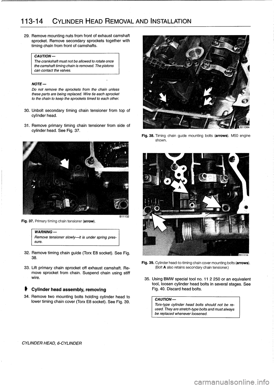
37
.
Fig
.
37
.
Primary
timing
chain
tensioner
(arrow)
.
WARNING
-
Remove
tensioner
slowly-¡t
ís
under
spring
pres-
sure
.
32
.
Remove
timing
chainguíde
(Tono
E8
socket)
.
See
Fig
.
38
.
33
.
Lift
primary
chain
sprocket
off
exhaust
camshaft
.
Re-
move
sprocket
from
chain
.
Suspend
chainusing
stiff
wire
.
Cylinder
head
assembly,
removing
34
.
Remove
two
mounting
bolts
holding
cylinder
head
to
lower
timing
chaincover
(Torx
E8
socket)
.
See
Fig
.
39
.
CYLINDER
HEAD,
6-CYLINDER
Fig
.
38
.
Timing
chain
guide
mounting
bolts
(arrows)
.
M50
engine
shown
.
Fig
.
39
.
Cylinder
head-to-timing
chain
covermounting
boits(arrows)
.
(Bolt
A
also
retains
secondary
chain
tensioner
.)
35
.
Using
BMMI
special
tool
no
.
11
2
250
or
an
equivalent
tool,
loosen
cylinder
head
bolts
in
several
stages
.
See
Fig
.
40
.
Discard
head
boits
.
CAUTION-
Torx-type
cylinder
head
bolts
should
not
be
re-
used
.
Theyare
stretch-type
bolts
and
must
atwaysbe
replaced
whenever
loosened
.
Page 91 of 759
CYLINDER
HEAD
AND
VALVETRAIN,
RECONDITIONING
Thís
section
provides
the
specifications
and
special
recon-
ditioning
information
necessary
to
repair
the
cylinder
heads
covered
by
this
manual
.
If
machine
shop
services
are
not
readily
available,
one
al-
ternative
is
to
install
a
remanufactured
cylinder
head
froman
authorized
BMW
dealer
.
Cylinder
head
NOTE-
When
replacing
the
cylinder
headon
engines
with
re-
movablecamshaft
carriers,
be
sure
to
check
the
cam-
shaft
carrier
bearing
surfaces
for
warpage
.
4-cylinder
1
140
.0
mm
(5
.512
in)
1
139
.55
mm
(5
.494
in)
6-cylinder
1
140
.0
mm
(5
.512
in)
1
139
.7
mm
(5
.500
in)
CYLINDER
HEAD
AND
VALVETRAIN
116-
7
A
The
disassembled
cylinder
head
should
be
inspected
for
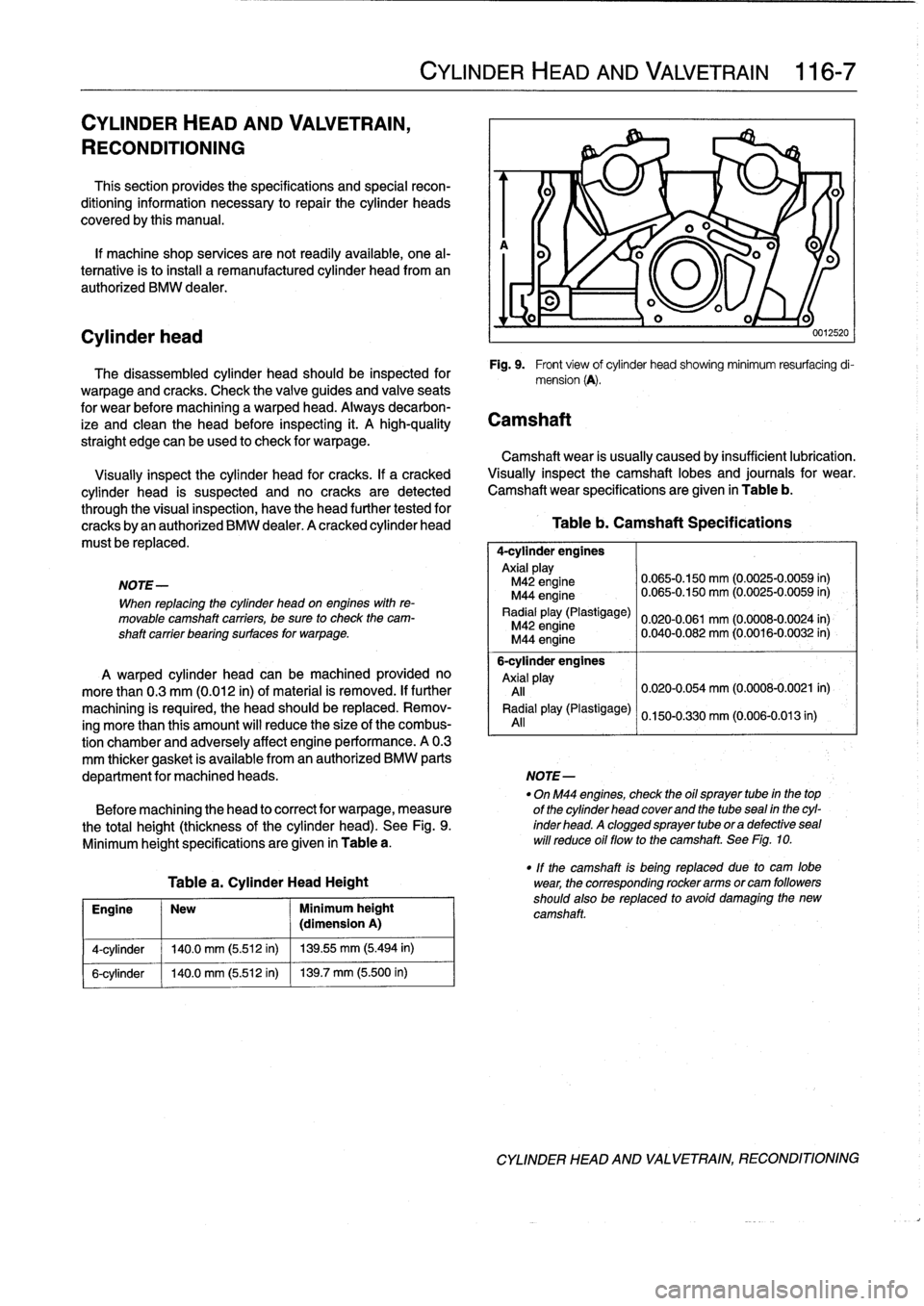
Fig
.
9
.
Front
víew
of
cylinder
head
showing
minimum
resurfacing
di-
warpage
and
cracks
.
Check
the
valve
guides
and
valveseats
mension
(A)
.
for
wear
before
machining
a
warped
head
.
Always
decarbon-
ize
and
clean
the
head
before
inspectiog
it
.
A
high-quality
Camshaft
straíght
edge
can
be
used
to
check
for
warpage
.
Camshaft
wear
is
usually
caused
by
insufficient
lubrication
.
Visually
inspect
the
cylinder
head
for
cracks
.
If
acracked
Visually
inspect
the
camshaft
lobes
and
journals
for
wear
.
cylinder
head
is
suspected
and
no
cracks
are
detected
Camshaftwear
specifications
are
given
in
Table
b
.
through
the
visual
inspection,
have
the
head
further
tested
for
cracks
byan
authorized
BMW
dealer
.
A
cracked
cylinder
head
Table
b
.
Camshaft
Specifications
must
be
replaced
.
4-cylinder
engines
Axialplay
M42
engine
0
.065-0
.150
mm
(0
.0025-0
.0059
in)
M44
engine
0
.065-0
.150
mm
(0
.0025-0
.0059
in)
Radial
play(Plastigage)
0
.020-0.061
mm
(0
.0008-0
.0024
in)
M42
engine
M44
engine
0
.040-0
.082
mm
(0
.0016-0
.0032
in)
6-cylinder
engines
A
warped
cylinder
head
can
be
machined
provided
no
Axial
pla
y
more
than
0
.3
mm
(0
.012
in)
of
material
is
removed
.
If
further
All
0
.020-0.054
mm
(0
.0008-0
.0021
in)
machining
is
required,
the
head
should
be
replaced
.
Remov-
Radial
play(Plastigage)
0
.150-0.330
mm
(0
.006-0.013
in)
ing
more
than
this
amount
will
reduce
the
size
of
the
combus-
All
tion
chamber
and
adversely
affect
engine
performance
.
A
0
.3
mm
thicker
gasket
is
available
from
an
authorized
BMW
parts
department
for
machined
heads
.
NOTE-
-
On
M44
engines,
check
the
oil
sprayer
tube
in
the
top
Before
machining
the
head
to
correct
for
warpage,
measure
of
the
cylinder
head
coverand
the
tubesea¡
in
the
cyl-
the
total
height(thicknessof
the
cylinder
head)
.
See
Fig
.
9
.
inderhead
.Acloggedsprayertubeoradefectiveseal
Minimum
height
specifications
are
given
in
Table
a
.
will
reduce
oil
flowto
the
camshaft
.
See
Fig
.
10
.
-
If
the
camshaft
is
being
replaced
due
to
cam
lobe
Table
a
.
Cylinder
Head
Height
wear,
the
corresponding
rockerarms
orcam
followers
Engine
New
Minimum
height
shouId
also
be
replaced
to
avofd
damaglng
the
new
(dimension
A)
camshaft
.
CYLINDER
HEAD
AND
VALVETRAIN,
RECONDITIONING
Page 102 of 759
117-
6
CAMSHAFT
TIMING
CHAIN
15
.
Insta¡¡
upper
timing
chaincover
:
17
.
Remove
crankshaft
locking
tool
from
transmission
bell-
"
Thoroughly
clean
profile
gasketgroove
and
all
sealing
housing
and
camshaft
locking
tool
from
rear
of
cylinder
surfaces
.
head
.
"
Applya
small
bead
ofsilicon
sealer
(3-Bond
1209®
or
equivalent)
to
upper
and
lower
joint
comers
where
18
.
Turn
engine
over
by
hand
in
direction
of
rotation
at
least
chaincover
meets
cylinder
head
.
two
full
rotations
.
Reinstall
camshaft
and
crankshaft
"
Insta¡¡
new
profile
gasket
to
groove
in
lowerchain
cover
.
locking
tools
to
check
engine
timing
.
Repeat
cam
timing
"
Protect
top
of
profile
gasket
using
thin
sheetmetal
procedure
if
tools
do
not
fit
easily
into
position
.
Remove
(BMW
special
tool
no
.
11
2
330
or
equivalent)
.
See
locking
tools
.
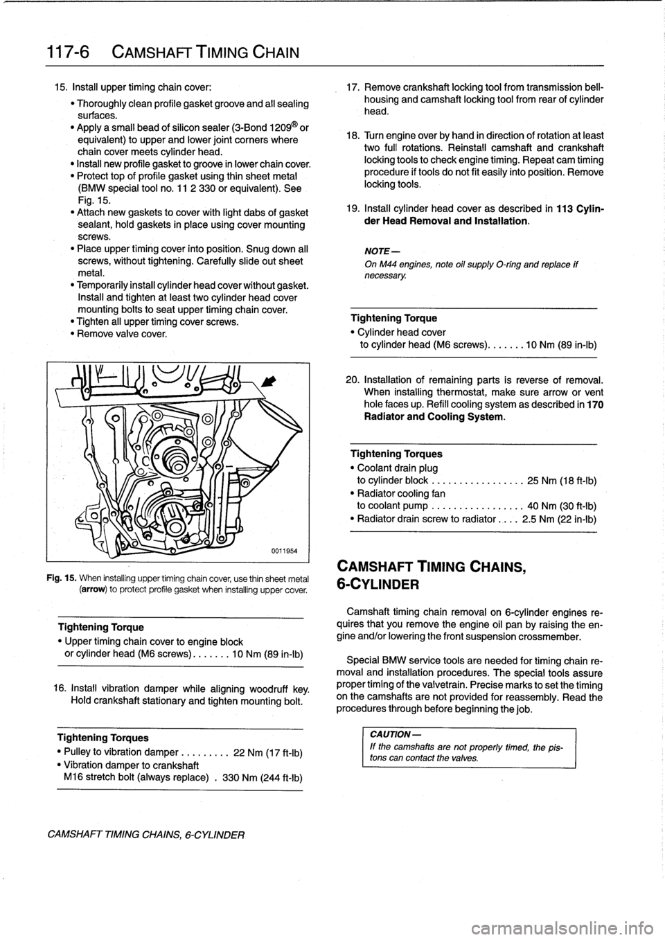
Fig
.
15
.
"
Attach
new
gaskets
to
cover
with
light
dabs
of
gasket
19
.
Install
cylinder
head
cover
as
described
in
113
Cylin-
sealant,
hold
gaskets
in
placeusing
cover
mounting
der
HeadRemoval
and
Installation
.
screws
.
"
Place
upper
timing
cover
into
position
.
Snug
down
al¡
NOTE-
screws,
without
tightening
.
Carefully
slide
out
sheet
OnM44
engines,
note
oil
supply
O-ring
and
replace
ff
metal
.
necessary
.
"
Temporarily
install
cylinder
head
cover
without
gasket
.
Insta¡¡
and
tighten
at
least
two
cylinder
head
cover
mounting
bolts
to
seat
upper
timing
chaincover
.
"
Tighten
all
upper
timing
cover
screws
.
Tightening
Torque
"
Remove
valve
cover
.
"
Cylinder
head
cover
to
cylinder
head
(M6
screws)
...
..
.
.
10
Nm
(89
ín-Ib)
-
CAMSHAFT
TIMING
CHAINS,
Fig
.
15
.
When
installing
upper
timing
chain
cover,
use
thin
sheetmetal
6-CYLINDER
(arrow)
to
protect
profile
gasket
when
installing
uppercover
.
Tightening
Torque
"
Upper
timing
chaincover
to
engine
block
or
cylinder
head
(M6
screws)
....
.
..
10
Nm
(89
in-lb)
16
.
Install
vibration
damper
while
aligning
woodruff
key
.
Hold
crankshaft
stationary
and
tighten
mounting
bolt
.
Tightening
Torques
I
CAUTION-
"
Pulley
to
vibration
damper
..
.
.
.
....
22
Nm
(17
ft-Ib)
lf
the
camshaftsare
not
properly
timed,
the
1
pis-
tons
can
contact
thevalves
.
"
Vibration
damper
tocrankshaft
M16
stretch
bolt
(always
replace)
.
330
Nm
(244
ft-Ib)
CAMSHAFT
TIMINGCHAINS,
6-CYLINDER
20
.
Installation
of
remaining
parts
is
reverse
of
removal
.
When
installing
thermostat,
make
sure
arrow
or
vent
hole
faces
up
.
Refill
cooling
system
as
described
in
170
Radiator
and
Cooling
System
.
Tighteníng
Torques
"
Coolant
drain
plug
to
cylinder
block
.
..
.
.
.
...
.
..
.....
25
Nm
(18
ft-Ib)
"
Radiator
cooling
fan
to
coolant
pump
.
..
.
...
...
..
.....
40
Nm
(30
ft-Ib)
"
Radiator
drain
screw
to
radiator
....
2
.5
Nm
(22
in-lb)
Camshaft
timing
chainremovalon
6-cylinder
engines
re-
quires
that
you
Rmove
the
engine
oil
pan
by
raising
the
en-
gine
and/or
lowering
the
front
suspension
crossmember
.
Special
BMW
service
tools
are
needed
for
timing
chain
re-
moval
and
installation
procedures
.
The
special
tools
assure
proper
timing
of
the
valvetrain
.
Precise
marks
to
setthe
timing
on
the
camshafts
arenot
provided
for
reassembly
.
Read
the
procedures
through
before
beginning
thejob
.
Page 117 of 759
NOTE
-
The
guide
tube
is
sealed
in
the
pan
with
an
O-ring
.
Check
that
theO-ring
comes
out
with
the
tube
.
Use
a
new
O-ring
when
installing
the
tube
.
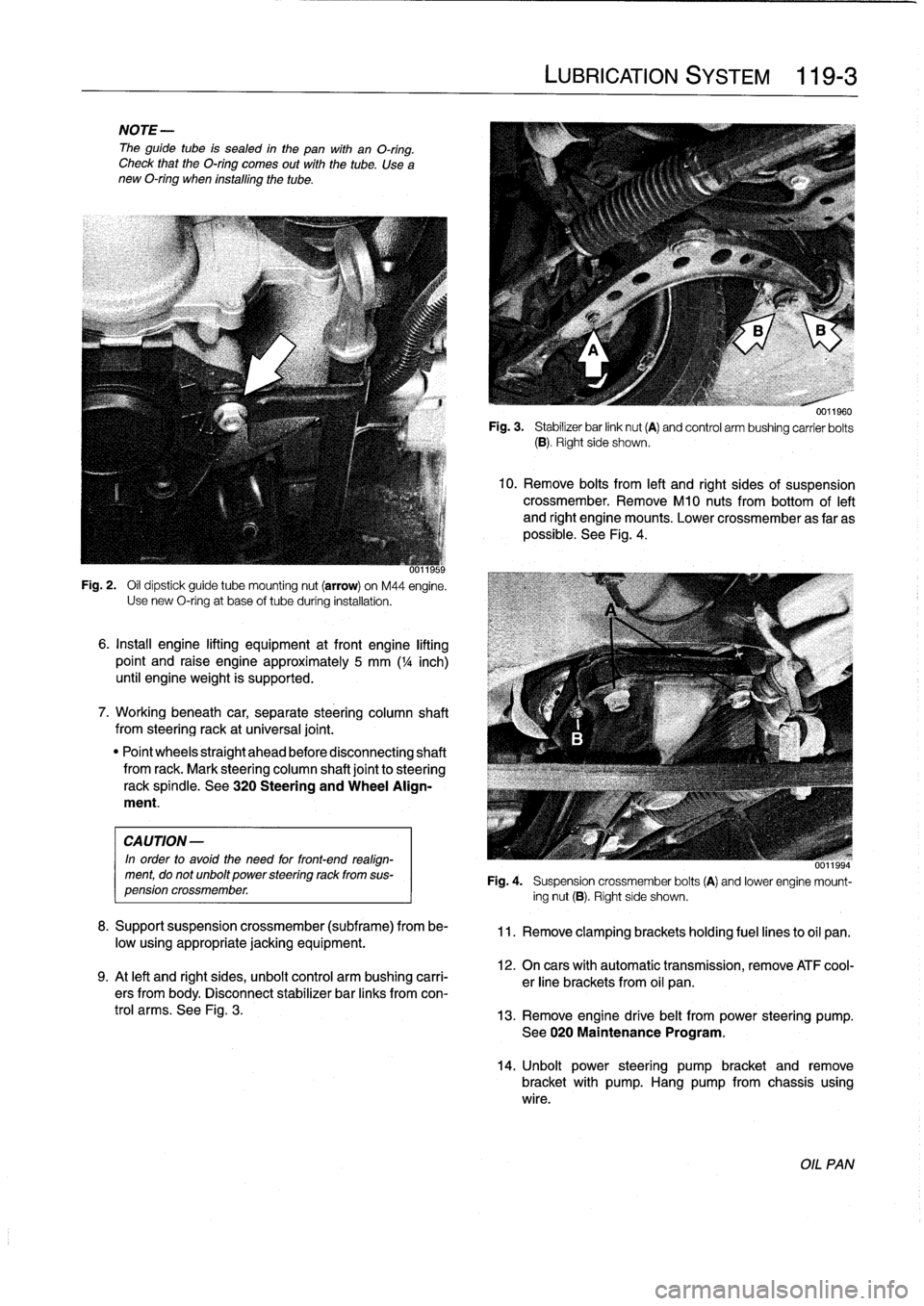
Fig
.
2
.
Oil
dipstick
guide
tube
mounting
nut
(arrow)
on
M44
engine
.
Use
new
O-ring
at
base
of
tube
during
installatidn
.
6
.
Install
engine
lifting
equipment
at
front
engine
lifting
point
and
raise
engine
approximately
5
mm
(
1
/4
inch)
until
engineweight
is
supported
.
7
.
Workingbeneath
car,
separate
steering
column
shaft
from
steeringrack
at
universal
joint
.
"
Point
wheels
straight
ahead
before
disconnecting
shaft
from
rack
.
Mark
steering
column
shaft
joint
to
steering
rackspíndle
.
See
320
Steering
and
Wheel
Align-
ment
.
CAUTION
-
In
order
to
avoíd
the
need
for
front-end
realign-
ment,
do
notunbolt
power
steering
rack
from
sus-
pension
crossmember
.
8
.
Supportsuspension
crossmember
(subframe)
from
be-
low
usingappropriate
jacking
equipment
.
9
.
At
left
and
right
sides,
unbolt
control
arm
bushing
carri-
ers
from
body
.
Disconnect
stabilizer
bar
links
fromcon-
trol
arms
.
See
Fig
.
3
.
LUBRICATION
SYSTEM
119-
3
0011960
Fig
.
3
.
Stabilizer
bar
link
nut
(A)
and
control
arm
bushing
carrier
bolts
(B)
.
Right
side
shows
.
10
.
Remove
bolts
from
left
and
right
sides
of
suspension
crossmember
.
RemoveM10
nuts
from
bottom
of
left
and
right
engine
mounts
.
Lower
crossmember
as
far
as
possible
.
See
Fig
.
4
.
uu1ibb4
Fig
.
4
.
Suspension
crossmember
bolts
(A)
and
lower
engine
mount-
ing
nut
(B)
.
Right
side
shows
.
11
.
Remove
clamping
brackets
holding
fuel
lines
to
oil
pan
.
12
.
On
cars
with
automatic
transmission,
remove
ATF
cool-
er
line
brackets
from
oil
pan
.
13
.
Remove
engine
drive
belt
from
power
steering
pump
.
See020
Maintenance
Program
.
14
.
Unbolt
power
steering
pumpbracket
andremove
bracket
with
pump
.
Hang
pump
from
chassis
using
wire
.
OIL
PAN
Page 118 of 759
119-
4
LUBRICATION
SYSTEM
15
.
Remove
oil
pan
screws
.
Lower
andremove
oil
pan
to-
ward
rear
.
Tightening
Torques
"
Control
arm
bushing
carrier
CAUTION-
to
body(M10
bolt)
...............
42
Nm
(31
ft-Ib)
'
lf
the
oil
pan
does
not
separate
easily
from
the
en-
"
Engine
mount
to
gine
cylinder
block,
make
sure
all
mounting
bolis
suspension
crossmember
(M10
nut)
.
42
Nm
(31
ft-Ib)
have
been
removed
.
If
necessary,
a
few
tapswith
"
Front
suspension
crossmember
a
rubber
mallet
shouldbreak
it
free
.
Never
pry
the
to
body
.
.
..
...
..
.
....
See
310
Front
SusPension
oil
pan
loose
.
"
Oil
pan
to
engine
block
(M6
bolt)
8
.8
grade
..
....
.
...
...
.
........
10
Nm
(89
in-lb)
16
.
Installation
is
reverse
of
removal
.
10
.9
grade
...
..
.
....
..
.
.
.
.......
12
Nm
(9
ft-Ib)
"
Thoroughly
clean
all
old
gasket
material
from
mating
"
Power
steering
pump
to
bracket
surfaces
anduse
a
new
gasket
.
(self-locking
nuts)
....
..
.
....
..
.
..
22
Nm
(16
ft-Ib)
"
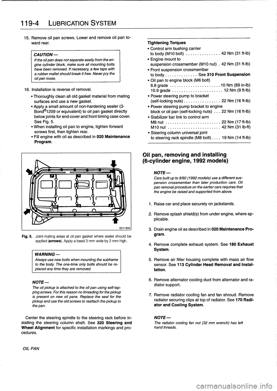
Applya
small
amount
of
non-hardening
sealer
(3-
"
Power
steering
pump
bracket
to
engine
Bond
O
l209
or
equivalent)
to
oil
pan
gasket
directly
block
or
oil
pan
(self-locking
nuts)
..
.
22
Nm
(16
ft-Ib)
below
joints
for
end
cover
and
front
timing
case
cover
.
"
Stabilizer
bar
link
to
control
arm
See
Fig
.
5
.
M8
nut
.................
...
.
...
22
Nm
(17
ft-Ib)
"
When
installing
oil
pan
to
engine,
tighten
forward
M10
nut
.....................
..
42
Nm
(31
Ib-ft)
screws
first,
then
tightenrear
.
"
Steering
column
universal
joint
"
Fill
engine
with
oil
as
described
in
020
Maintenance
to
steering
rack
spindle
(M8
bolt)
....
19
Nm
(14
ft-ib)
Program
.
0011950
Fig
.
5
.
Joint-mating
areas
at
oil
pan
gasket
where
sealer
should
be
applied
(arrows)
.
Apply
a
bead
3
mm
wideby
2
mm
high
.
OIL
PAN
WARNING
-
Always
use
new
bolis
when
mounting
the
subframe
to
the
body
.
The
one-timeonly
bolis
shouldbe
re-
placed
any
timethey
are
removed
.
NOTE-
The
oil
pickup
is
attached
to
the
oil
pan
using
self-tap-
ping
screws
.
For
this
reasonno
threading
for
the
pickup
is
present
on
new
oil
pans
.
Replace
the
seal
for
the
pickup
and
use
the
oíd
screws
to
rea
ttach
the
pickup
to
the
pan
.
Oil
pan,
removing
and
installing
(6-cylinder
engine,
1992models)
NOTE-
Cars
built
up
to
9/92
(1992models)usea
different
sus-
pension
crossmember
than
later
production
cars
.
Oil
pan
removalprocedureon
the
earlier
cars
requires
that
the
engine
be
raised
and
supportedfrom
above
.
1
.
Raise
car
and
place
securely
on
jackstands
.
2
.
Remove
splash
shield(s)
from
under
engine,
where
ap-
plicable
.
3
.
Drain
engine
oil
as
described
in
020
Maintenance
Pro-
gram
.
4
.
Remove
complete
exhaust
system
.
See180
Exhaust
System
.
5
.
Remove
air
filter
housing
complete
with
mass
air
flow
sensor
.
See
113
Cylinder
Head
Removal
and
Instal-
lation
.
6
.
Remove
alternator
cooling
duct
from
alternator
and
ra-
diator
support
.
7
.
Remove
radiator
cooling
fan
and
fan
shroud
.
Remove
radiator
securing
clips
at
top
of
radiator
.
See
170
Radi-
ator
and
Cooling
System
.
Center
the
steering
spindle
to
the
steering
rack
before
in-
NOTE-
stalling
the
steering
column
shaft
.
See
320
Steering
and
The
radiator
cooling
fan
nut(32
mm
wrench)
has
left
Wheel
Alignment
for
specific
installation
markings
and
pro-
hand
threads
.
cedures
.
Page 120 of 759
119-
6
LUBRICATION
SYSTEM
17
.
Raise
engine
as
much
as
possible
.
Check
carefully
for
22
.
Installation
is
reverse
of
removal
.
obstructions,
wiring
harness
clearance
and
pinched
hoses
or
lines
as
engine
is
raised
.
"
When
installing
oil
pan,
apply
a
b
d
of
non-hardening
sealing
compound
(3-Bond
1209
0
or
equivalent)
to
18
.
Remove
oil
pan
mounting
bolts
and
lower
oil
pan
to
front
and
rear
end
cover
seam
areas
on
block
.
subframe
crossmember
.
"
Position
oil
pump
pickup
tube
and
oil
pan
onto
block
and
install
pickup
tube
using
a
new
gasket
.
"
Be
sure
tab
on
gasket
faces
down
towards
intake
of
NOTE-
pickup
tube
.
If
the
oil
pan
does
not
separate
easily
from
the
engine
"
Tightenforward
oil
pan
screws
first,
then
tighten
rear
.
cylinder
block,
afew
taps
with
arubber
mallet
should
"
Fill
engine
with
oil
as
described
in
020
Maintenance
break
it
free
.
Do
not
pry
the
oil
pan
loose
.
Program
.
"
After
adding
engine
oil,
start
and
run
engine
.
Raise
en-
19
.
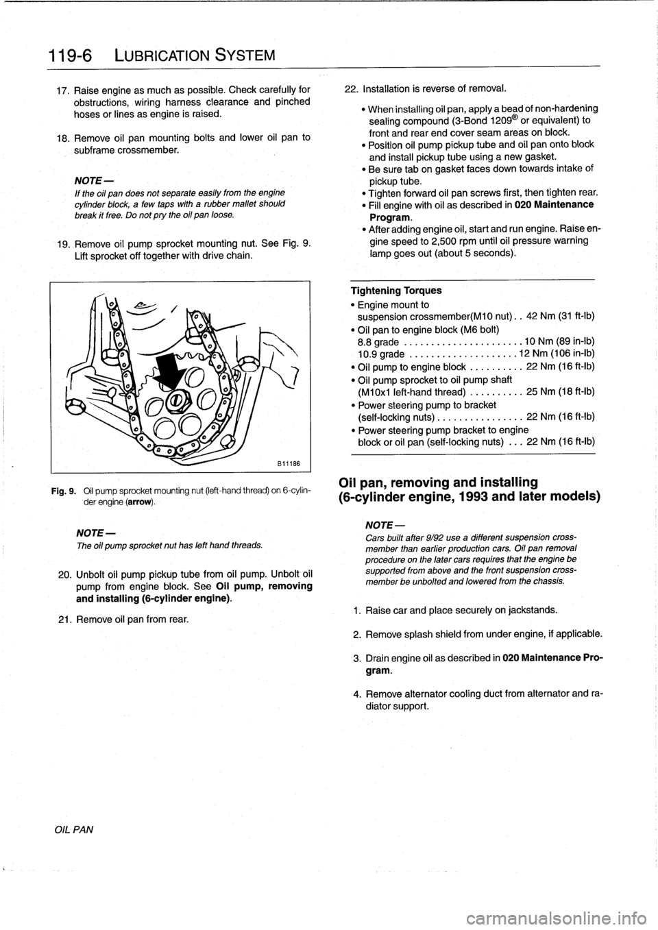
Remove
oil
pump
sprocket
mounting
nut
.
See
Fig
.
9
.
gine
speed
to
2,500
rpm
until
oil
pressure
warning
Lift
sprocket
off
together
with
drive
chain
.
lampgoes
out(about
5seconds)
.
Fig
.
9
.
Oil
pump
sprocket
mounting
nut
(left-hand
thread)
on
6-cylin-
OII
pan,
removing
and
installing
derengine(arrow)
.
(6-cylinder
engine,
1993
and
later
modeis)
NOTE-
The
oíl
pump
sprocket
nut
has
left
hand
threads
.
20
.
Unbolt
oil
pump
pickup
tubefrom
oil
pump
.
Unbolt
oil
pump
from
engine
block
.
See
Oil
pump,
removing
and
installing
(6-cylinder
engine)
.
21
.
Remove
oil
pan
from
rear
.
Tightening
Torques
"
Engine
mount
to
suspension
crossmember(M10
nut)
..
42
Nm
(31
ft-Ib)
"
Oil
pan
to
engine
block
(M6
bolt)
8
.8
grade
....
..
.
...
...
.
........
10
Nm
(89
in-lb)
10
.9
grade
.
.
..
.
..
...
.
.
.
.
.
.....
12
Nm
(106
in-lb)
"
Oil
pump
to
engine
block
.
...
...
.
..
22
Nm
(16
ft-Ib)
"
Oil
pump
sprocket
to
oil
pump
shaft
(M1
0x1
left-hand
thread)
...
..
.
.
..
.
25
Nm
(18
ft-Ib)
"
Power
steering
pump
to
bracket
(self-locking
nuts)
.....
.
....
..
.
...
22
Nm
(16
ft-lb)
"
Power
steering
pump
bracket
to
engine
block
or
oil
pan
(self-locking
nuts)
.
..
22
Nm
(16
ft-Ib)
NOTE-
Cars
built
after
9/92
use
a
different
suspension
cross-
member
¡han
earfier
productíon
cars
.
Oil
pan
removal
procedure
on
the
later
cars
requíres
that
the
engine
be
supported
from
aboye
and
the
front
suspension
cross-
member
be
unbolted
and
loweredfrom
the
chassis
.
1
.
Raisecar
and
place
securely
on
jackstands
.
2
.
Remove
splash
shield
fromunder
engine,
if
applicable
.
3
.
Drain
engine
oil
as
descríbed
in
020
Maintenance
Pro-
gram
.
4
.
Remove
alternator
cooling
duct
from
alternator
and
ra-
diator
support
.
Page 121 of 759
5
.
Remove
air
filter
housingcomplete
with
mass
air
flow
sensor
.
See113
Cylinder
HeadRemoval
and
Instal-
lation
.
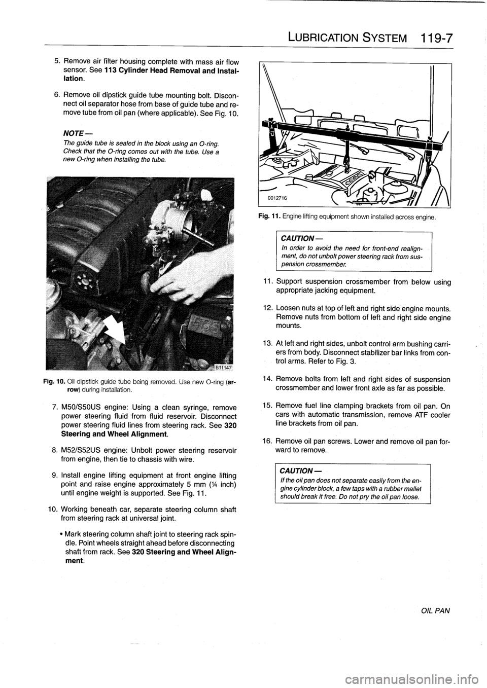
6
.
Remove
oil
dipstick
guide
tube
mounting
bolt
.
Discon-
nect
oil
separator
hose
frombase
of
guide
tube
and
re-
move
tubefrom
oil
pan
(where
applicable)
.
See
Fig
.
10
.
NOTE-
The
guide
tube
is
sealed
in
the
blockusing
an
O-ring
.
Check
that
the
O-ring
comes
out
with
the
tube
.
Use
a
new
O-ring
when
installing
the
tube
.
Fig
.
10
.
Oil
dipstick
guide
tube
being
removed
.
Use
new
O-ring
(ar-
row)
during
installation
.
7
.
M50/S50US
engine
:
Using
a
clean
syringe,
remove
power
steering
fluid
from
fluid
reservoir
.
Disconnect
power
steering
fluid
lines
from
steering
rack
.
See
320
Steering
and
Wheel
Alignment
.
8
.
M52/S52US
engine
:
Unbolt
power
steering
reservoir
from
engíne,
then
tie
to
chassis
with
wire
.
9
.
Insta¡¡
engine
lifting
equipment
atfront
engine
lifting
point
and
raise
engine
approximately
5
mm
('/a
inch)
until
engineweight
is
supported
.
See
Fig
.
11
.
10
.
Workingbeneath
car,
separate
steering
column
shaft
from
steeringrack
at
universal
joint
.
"
Mark
steering
column
shaft
jointto
steering
rack
spin-
dle
.
Point
wheels
straight
ahead
before
disconnecting
shaft
from
rack
.
See
320
Steering
and
Wheel
Align-
ment
.
LUBRICATION
SYSTEM
119
Fig
.
11
.
Engine
lifting
equipment
shown
installed
acrossengíne
.
CA
UTION-
In
order
to
avoid
the
need
for
front-end
realign-
ment,
donot
unbolt
power
steering
rack
from
sus-
pension
crossmember
.
11
.
Support
suspension
crossmember
from
below
using
appropriate
jacking
equipment
.
12
.
Loosen
nuts
at
top
of
left
and
right
side
engine
mounts
.
Remove
nuts
from
bottom
of
left
and
right
side
engine
mounts
.
13
.
At
left
and
right
sides,
unbolt
control
arm
bushíng
carri-
ers
from
body
.
Disconnect
stabilizer
bar
links
fromcon-
trol
arms
.
Refer
to
Fig
.
3
.
14
.
Remove
bolts
from
left
and
right
sides
of
suspension
crossmember
and
lower
front
axle
as
far
as
possible
.
15
.
Remove
fuelline
clamping
brackets
from
oil
pan
.
On
cars
with
automatic
transmission,
remove
ATF
cooler
line
brackets
from
oil
pan
.
16
.
Remove
oil
pan
screws
.
Lower
and
remove
oil
pan
for-
ward
to
remove
.
CA
UTION-
If
the
oil
pan
does
not
separate
easily
from
the
en-
gine
cylinder
block,
a
few
taps
with
a
rubber
mallet
shouldbreak
it
free
.
Do
notpry
the
oil
pan
loose
.
OIL
PAN
Page 122 of 759
119-
8
LUBRICATION
SYSTEM
17
.
Installation
is
reverse
of
removal
.
"
Thoroughly
clean
all
old
gasket
material
from
mating
surtaces
anduse
a
new
gasket
.
"
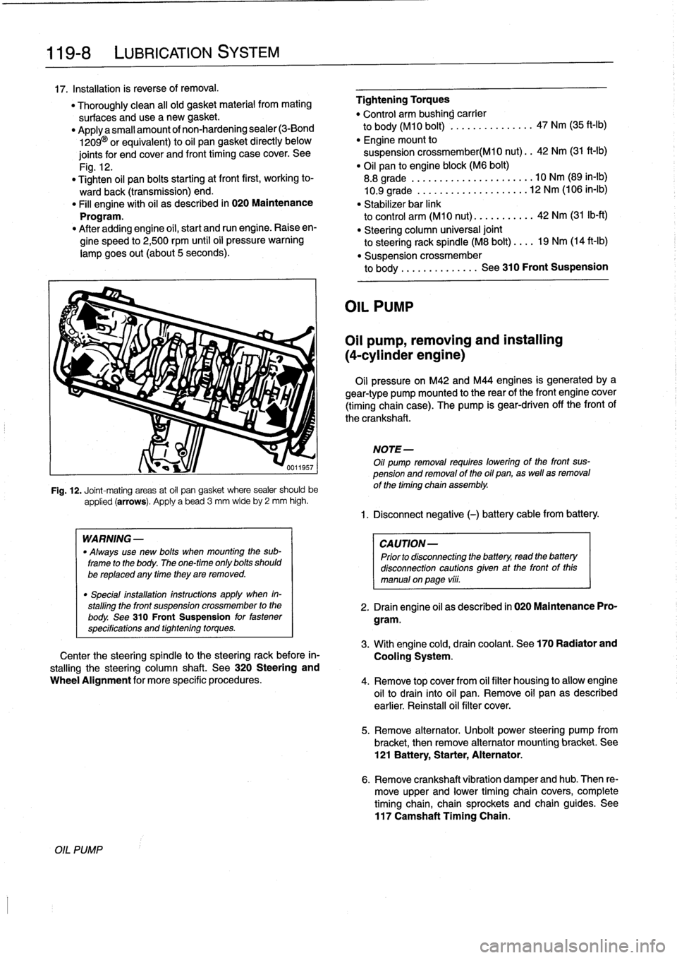
Applya
small
amount
of
non-hardening
sealer
(3-Bond
1209
0
or
equivalent)
to
oil
pan
gasket
directly
below
joints
for
and
cover
and
front
timing
case
cover
.
See
Fig
.
12
.
"
Tighten
oil
pan
bolts
starting
at
front
first,
working
to-
wardback
(transmission)
end
.
"
Fill
engine
with
oil
as
described
in
020
Maintenance
Program
.
"
After
addingengine
oil,
start
and
run
engine
.
Raiseen-
gine
speed
to
2,500
rpm
until
oíl
pressure
warning
lampgoes
out
(about
5seconds)
.
OIL
PUMP
applied
(arrows)
.
Apply
a
bead
3
mm
wideby
2
mm
high
.
WARNING
-
"
Always
use
new
bolts
when
mounting
the
sub-
frame
to
the
body
.
The
one-time
only
bolts
should
be
replaced
any
timethey
are
removed
.
"
Special
installation
instructions
apply
when
in-
stalling
the
front
suspension
crossmember
to
the
body
.
See
310
Front
Suspension
for
fastener
specifications
and
tightening
torques
.
Fig
.
12
.
Joint-mating
areas
at
oil
pan
gasket
where
sealer
should
be
Center
the
steering
spindle
to
the
steering
rack
before
in-
stalling
the
steering
column
shaft
.
See
320
Steering
and
Wheel
Alignment
for
more
specific
procedures
.
Tightening
Torques
"
Control
arm
bushing
carrier
to
body
(M10
bolt)
...............
47
Nm
(35
ft-Ib)
"
Engine
mount
to
suspension
crossmember(M10
nut)
..
42
Nm
(31
ft-Ib)
"
Oil
pan
to
engine
block
(M6
bolt)
8
.8
grade
...........
.......
....
10
Nm
(89
in-lb)
10
.9
grade
...........
..
...
...
.
12
Nm
(106
in-lb)
"
Stabilizer
bar
link
to
control
arm
(M10
nut)
.......
....
42
Nm
(31
Ib-ft)
"
Steering
column
universal
joint
to
steering
rack
spindle
(M8
bolt)
....
19
Nm
(14
ft-Ib)
"
Suspensíon
crossmember
to
body
...
...
.
...
..
.
.
See
310
Front
Suspension
OIL
PUMP
Oil
pump,
removing
and
installing
(4-cylinder
engine)
Oil
pressure
on
M42
and
M44
engines
is
generatedbya
gear-type
pump
mounted
to
the
rear
of
the
front
engine
cover
(timing
chaincase)
.
The
pump
is
gear-driven
off
the
front
of
the
crankshaft
.
NOTE-
Oil
pump
removal
requires
lowering
of
the
front
sus-
pension
and
removal
of
the
oil
pan,
as
well
asremoval
of
the
timing
chain
assembly
.
1
.
Disconnect
negative
(-)
battery
cable
from
battery
.
CAUTION-
Prior
to
disconnectiog
the
battery,
read
the
battery
disconnection
cautions
given
at
the
front
of
this
manual
on
paga
vÍii
.
2
.
Drain
engine
oil
as
described
in
020
Maintenance
Pro-
gram
.
3
.
Withengine
cold,
drain
coolant
.
See
170
Radiator
and
Cooling
System
.
4
.
Remove
top
cover
from
oil
filter
housing
to
allow
engine
oil
to
drain
into
oil
pan
.
Remove
oil
pan
as
described
earlier
.
Reinstall
oil
filter
cover
.
5
.
Remove
alternator
.
Unbolt
power
steering
pump
from
bracket,
then
remove
alternator
mountíng
bracket
.
See
121
Battery,
Starter,
Alternator
.
6
.
Remove
crankshaft
vibration
damper
andhub
.
Then
re-
move
upper
and
lower
timing
chain
covers,
complete
timingchain,
chain
sprockets
and
chain
guides
.
See
117
Camshaft
Tíming
Chain
.
Page 124 of 759
119-
1
0
LUBRICATION
SYSTEM
Oil
pump,
removing
and
installing
(6-cylinder
engine)
Oil
pressure
on
the
6-cylinder
engines
is
generated
by
a
gear-type
pump
bolted
to
the
bottom
of
the
engine
block
.
The
oil
pump
is
chain
driven
off
the
front
of
the
crankshaft
.
NOTE-
Oil
pump
removal
requires
raising
the
engine
(cars
built
up
to
9-92)
or
lowering
the
front
suspension
crossmem-
ber
(cars
built
from
9-92)
to
remove
the
oil
pan
.
1.
Drain
oil
as
described
in
020
Maintenance
Program
.
2
.
Remove
oil
pan
as
described
earlier
.
3
.
Remove
oil
pump
sprocket
mounting
nut
(left-hand
thread)
.
See
Fig
.
16
.
Lift
sprocket
off
together
with
drive
chain
.
Fig
.
16
.
Oil
pump
sprocket
mounting
nut
(left-hand
thread)
on
6-cylin-
der
engine
(arrow)
.
4
.
Remove
mounting
bolts
from
oil
pump
and
oil
pump
pickup
tube
.
Withdraw
pump
.
NOTE-
Note
any
spacers
between
pump
and
engine
block
.
See
Fig
.
17
.
"
Note
position
of
locating
dowels
.
OIL
PUMP
811186
0011952
Fig
.
17
.
Oil
pump
mounting
points
(1)
and
pickup
tube
mountíng
points
(2)
.
5
.
Remove
coverfrom
oil
pump
and
check
for
wear
or
scoring
.
Spin
oil
pump
shaft
and
check
that
gears
turn
smoothly
.
Replace
pump
if
gears
spinwith
difficulty
or
any
wear
is
present
.
6
.
Installation
is
reverse
of
removal,
noting
the
following
:
"
Align
sprocket
splines
to
oil
pump
shaft
splines
before
tightening
sprocket
nut
.
Tightening
Torques
"
Oil
pump
to
engine
block
(M8)
......
22
Nm
(16
ft-Ib)
"
Oil
pan
to
engine
block
(M6
bolt)
8
.8
grade
..
...
.
...
...
.
.........
10
Nm
(89
in-lb)
10
.9
grade
.
...
.
..
....
.
........
12
Nm
(106
in-lb)
"
Oil
pump
sprocket
to
oil
pump
shaft
(M1
0x1
left-hand
thread)
..........
25
Nm
(18
ft-Ib)
Page 226 of 759
230-
6
MANUAL
TRANSMISSION
Transmission,
removing
and
installing
1
.
Disconnect
negative
(-)
cable
from
battery
.
CAUTION-
Prior
to
disconnecting
the
battery,
read
the
battery
disconnection
cautions
given
at
the
front
of
this
manual
onpage
viii
.
2
.
Insta¡¡
enginesupportacrossengine
bay
.
Raise
engine
so
that
weight
of
engine
ís
supported
.
See
Fig
.
10
.
Fig
.
10
.
Engine
support
equipment
used
to
support
engine
from
above
before
removing
transmission
.
3
.
Raise
vehicle
to
gain
access
to
underside
of
car
.
4
.
Support
transmission
with
transmission
jack
.
lf
applica-
ble,
remove
reinforcing
cross
brace
from
belowen-
gine/transmission
.
5
.
Disconnect
harnesscon
nector
from
reverse
light
switch
on
transmission
.
6
.
Remove
completeexhaustsystem
and
heat
shield
.
See
180
Exhaust
System
.
NOTE-
Disconnect
oxygensensor
hamess
connector(s)be-
fore
lowering
exhaust
system
.
7
.
Remove
driveshaft
.
See260
Driveshaft
.
8
.
Disconnect
shift
rod
from
transmission
selectorshaft
.
See
Fig
.
11
.
9
.
Disconnect
shift
console
fromtop
of
transmission
.
See
250
Gearshift
Linkage
.
TRANSMISSION
REMOVAL
AND
INSTALLATION
Washers
Shift
Shift
rod
rod
retaining
clip
0
0
,
Fig
.
11
.
Shift
lever
to
transmission
connection
.
Shift
console
0012024
10
.
Unbolt
clutch
slave
cylinder
from
sideof
transmission
.
Do
not
disconnect
fluid
hose
.
Suspend
slavecylinder
from
chassis
using
stiff
wire
.
CAUTION-
Do
not
operate
clutch
pedal
with
slave
cylinder
re-
moved
from
transmission
.
11
.
Support
transmission
from
below
with
jack
.
Remove
rear
support
crossmember
from
transmission
.
See
Fig
.
12
.
Fig
.
12
.
Rear
transmission
crossmember
(arrow)
.
12
.
Lower
transmission/engine
assembly
until
it
rests
on
front
suspension
crossmember
.
CAUTION-
Tilting
the
engine
to
lower
thetransmission
can
lead
to
damage
to
various
componente
due
to
lackof
clearance
at
rear
of
engine
-On
cars
with
AST
remove
throttle
body
before
tilt-
ing
engine
.
-Remove
brace
fluid
reservoir
if
necessary
.
0013135