rear main seal BMW M3 1993 E36 Workshop Manual
[x] Cancel search | Manufacturer: BMW, Model Year: 1993, Model line: M3, Model: BMW M3 1993 E36Pages: 759
Page 40 of 759
020-
1
8
MAINTENANCE
PROGRAM
Fig
.
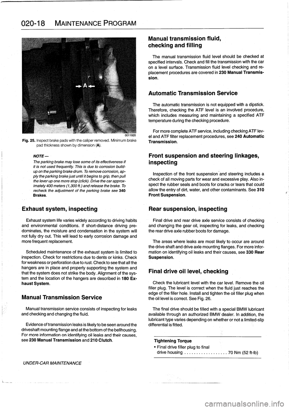
25
.
Inspect
brake
pads
with
the
caliper
removed
.
Minimum
brake
pad
thickness
shown
by
dimension
(A)
.
NOTE-
The
parking
brake
may
lose
some
of
its
effectiveness
if
it
is
not
used
frequently
.
This
is
due
to
corrosion
build-
up
on
the
parking
brake
drum
.
To
remove
corrosion,
ap-
plythe
parking
brake
just
until
it
begins
togrip,
then
pulí
the
lever
up
one
more
stop
(click)
.
Drive
thecar
approx-
imately
400
meters
(1,300
ft
.)
and
release
the
brake
.
To
recheck
the
adjustment
of
the
parking
brake
see340
Brakes
.
UNDER-CAR
MAINTENANCE
0011920
Manual
transmission
fluid,
checking
and
filling
The
manual
transmission
fluid
leve¡
should
be
checked
at
specified
intervals
.
Check
and
fill
the
transmission
with
the
car
ona
leve¡
surface
.
Transmission
(luid
leve¡
checking
and
re-
placement
procedures
are
covered
in
230
Manual
Transmis-
sion
.
Automatic
Transmission
Service
The
automatic
transmission
is
not
equipped
with
a
dipstíck
.
Therefore,
checking
the
ATF
level
is
an
ínvolved
procedure,
which
includes
measuring
and
maintaining
a
specified
ATF
temperature
during
the
checking
procedure
.
For
more
complete
ATF
service,
including
checking
ATF
lev-
e¡
and
ATF
filter
replacement
procedures,
see
240
Automatic
Transmission
.
Front
suspension
and
steering
linkages,
inspecting
Inspection
of
the
front
suspension'and
steering
includes
a
check
of
all
moving
parts
for
wear
and
excessive
play
.
Also
in-
spect
the
rubber
seals
and
boots
for
cracks
or
tears
that
could
allow
the
entry
of
dirt,
water,
and
other
contaminants
.
See
310
Front
Suspension
.
Exhaust
system,
inspecting
Rear
suspension,
inspecting
Exhaust
system
life
varies
widely
according
to
driving
habits
Final
drive
and
rear
drive
axle
service
consists
of
checking
and
environmental
conditions
.
If
short-distance
driving
pre-
and
changing
the
gear
oil,
inspecting
for
leaks,
and
checking
dominates,
the
moisture
and
condensation
in
the
system
will
the
rear
drive
axle
rubber
boots
for
damage
.
not
fully
dryout
.
This
will
lead
to
early
corrosion
damage
and
more
frequent
replacement
.
The
areas
where
leaks
are
most
likely
to
occur
are
around
the
driveshaft
and
drive
axle
mounting
flanges
.
For
more
infor
Scheduled
maintenance
of
the
exhaust
system
is
limitedlo
mation
on
ídentifying
oil
leaks
and
their
causes,
see330
Rear
inspection
.
Check
for
restrictions
due
to
dents
or
kinks
.
Check
Suspension
.
for
weakness
or
perforation
due
to
rust
.
Check
lo
see
that
all
the
hangers
are
in
place
and
properly
supporting
the
system
and
that
the
system
does
not
strike
the
body
.
Alignment
of
the
sys-
Final
drive
oil
leve¡,
checking
temand
the
location
of
the
hangers
aredescribed
in
180
Ex-
haust
System
.
Check
the
lubricant
leve¡
with
thecar
level
.
Remove
the
oil
filler
plug
.
The
leve¡
is
correct
when
the
fluidjust
reaches
the
edge
of
the
filler
hole
.
Install
and
tighten
the
oil
filler
plug
when
Manual
Transmission
Service
the
oil
level
is
correct
.
See
Fig
.
26
.
Manual
transmissionservice
consists
of
inspectingfor
leaks
The
final
drive
should
be
filled
with
a
special
BMW
lubricant
and
checking
and
changing
the
fluid
.
available
through
an
authorized
BMW
dealer
.
In
addition,
the
lubricant
type
varies
depending
onwhether
or
nota
limited-slip
Evidence
of
transmissionleaks
is
fkely
to
beseenaround
the
differential
is
fitted
.
driveshaft
mounting
flange
and
at
the
bottom
of
the
bellhousing
.
For
more
information
on
identifying
oil
leaks
and
their
causes,
see230ManualTransmissionand210
Clutch
.
Tightening
Torque
"
Finaldrive
filler
plug
to
final
drive
housing
..................
70
Nm
(52
ft-Ib)
Page 48 of 759
100-6
ENGINE-GENERAL
Cylinder
compression,
checking
A
compression
tester
is
needed
to
make
a
compression
test
.
To
obtain
accurate
test
results,
the
battery
and
starter
must
be
capable
of
cranking
the
engine
at
250-300
rpm,
and
theen-
gine
should
be
at
normal
operating
temperature
.
Use
com-
pressed
air
to
clean
aroundthe
spark
plugs
before
removal
.
1
.
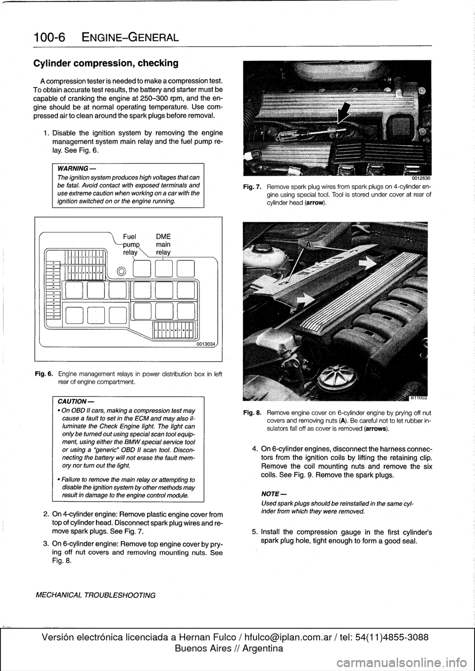
Disable
the
ignítion
system
by
removing
the
engine
management
system
main
relay
and
the
fuel
pump
re-
¡ay
.
See
Fig
.
6
.
WARNING
-
The
ignítion
system
produces
high
voltages
that
canbe
fatal
.
Avoid
contact
with
exposed
termínals
and
useextreme
caution
when
working
on
acar
wíth
the
ignítion
switched
on
or
the
engine
running
.
Fuel
DM
E
pump
main
re
ay
rel
ay
o
oa
ooa
.,
o00
oao
Fig
.
6
.
Engine
management
relays
in
power
distribution
box
inleft
rear
of
engine
compartment
.
CAUTION-
"
On
OBD
11
cars,
making
a
compression
test
may
causea
faultto
set
in
the
ECM
and
may
also
il-
luminate
the
Check
Engine
light
.
The
light
can
only
be
tumed
out
using
special
scan
tool
equip-
ment,using
eíther
the
BMW
specialservíce
tool
or
using
a
"generic"
OBD
11
scan
tool
.
Discon-
necting
the
battery
will
not
erase
the
fault
mem-
orynor
turn
outthe
light
.
0013034,
0012630
Fig
.
7
.
Remove
spark
plug
wires
from
spark
plugs
on
4-cylinder
en-
gine
using
special
tool
.
Tool
is
stored
under
cover
at
rear
of
cylinder
head
(arrow)
.
Fig
.
8
.
Remove
engine
cover
on
6-cylinder
engine
byprying
off
nut
covers
and
removing
nuts
(A)
.
Be
careful
not
to
let
rubber
in-
sulators
fall
off
as
cover
is
removed
(arrows)
.
4
.
On
6-cylinder
engines,
disconnect
the
harness
connec-
tors
from
the
ignítion
coils
by
lifting
the
retaining
clip
.
Remove
the
coil
mounting
nuts
andremove
the
six
coils
.
See
Fig
.
9
.
Remove
the
sparkplugs
.
"
Failure
to
remove
the
main
relay
or
attempting
to
disable
the
ignítion
system
by
other
methods
may
resultin
damage
to
the
engine
control
module
.
NOTE-
Used
sparkplugs
should
be
reinstalled
in
the
same
cyl-
2
.
On
4-cylinder
engine
:
Remove
plastic
engine
cover
from
inder
fromwhich
they
were
removed
.
top
of
cylinder
head
.
Disconnect
spark
plug
wires
and
re-
move
spark
plugs
.
See
Fig
.
7
.
5
.
Insta¡¡
the
compression
gauge
in
the
first
cylinder's
3
.
On
6-cylinder
engine
:
Remove
top
engine
coverby
pry-
spark
plug
hole,
tight
enough
to
form
a
good
seal
.
ing
off
nut
covers
and
removing
mounting
nuts
.
See
Fig
.
8
.
MECHANICAL
TROUBLESHOOTING
Page 61 of 759
14
.
Unbolt
power
steering
fluid
reservoir
from
íts
mounting
bracket
.
Use
stiff
wire
to
hang
reservoir
to
one
side
.
Do
not
disconnect
fluid
lines
.
15
.
Remove
power
steering
pump
drive
belt
and
remove
pump
from
its
mounting
bracket
.
Use
stiff
wire
to
hang
pump
from
body
.
16
.
On
cars
with
automatic
transmission
remove
front
and
rear
brackets
holding
automatic
transmission
cooler
linesto
engine
.
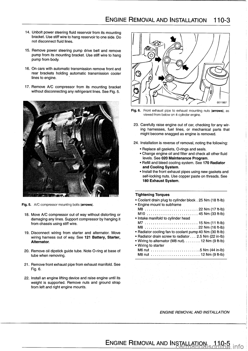
17
.
Remove
A/C
compressor
from
its
mounting
bracket
without
disconnecting
any
refrigerantlines
.
See
Fig
.
5
.
ENGINE
REMOVAL
AND
INSTALLATION
110-
3
21
.
Remove
front
exhaust
pipefrom
exhaust
manifold
.
See
Fig
.
6
.
22
.
Install
an
engine
lifting
device
and
raise
engine
until
its
weight
is
supported
.
Remove
nuts
and
ground
strap
from
left
and
right
engine
mounts
.
0011967
Fig
.
6
.
Front
exhaustpipe
to
exhaust
mounting
nuts
(arrows),
as
viewed
from
below
on
4-cylinder
engine
.
23
.
Carefully
raíse
engine
out
of
car,
checking
for
any
wir-
ing
harnesses,
fuel
lines,
or
mechanical
parts
that
might
become
snagged
as
engine
is
removed
.
24
.
Installation
is
reverse
of
removal,
noting
the
following
:
"
Replace
all
gaskets,
O-rings
and
seals
.
"
Change
engine
oil
and
filter
and
check
al¡
other
fluid
levels
.
See020
Maintenance
Program
.
"
Refill
and
bleed
cooling
system
.
See
170
Radiator
and
Cooling
System
.
"
Insta¡¡
the
front
exhaust
pipes
using
new
gaskets
and
self-locking
nuts
.
Use
copper
pasteon
threads
.
See
180
Exhaust
System
.
Tightening
Torques
"
Coolant
drain
plug
to
cylinder
block
.
25
Nm
(18
ft-Ib)
Fig
.
5
.
A/
C
compressor
mounting
bolts
(arrows)
.
"
Engine
mount
to
subframe
M8
......:...
..
..
..
......,:..
22
Nm
(17
ft
-
1b)
,
18
.
Move
A/C
compressor
out
of
way
without
distorting
or
M10
.
...
.
..
...
.
.
...........
45
Nm
(33
ft'-Ib)
damaging
any
lines
.
Support
compressor
by
hanging
it
"
Intake
manifold
to
cylinder
head
from
chassis
using
stiff
wire
.
M7
.....
.
..
...
..
..
...........
15
Nm
(11
ft-Ib)
M8
...
.
.
.
..
..
...
..
...........
22
Nm
(16
ft-Ib)
19
.
Disconnect
wiring
from
starter
and
alternator
.
Move
`
"
Radiator
cooling
fan
to
coolant
pump40
Nm
(30
ft-Ib)
wiring
harness
out
of
way
.
See
121
Battery,
Starter,
"
Radiator
drain
screw
to
radiator
...
2
.5
Nm
(22
in-lb)
Alternator
.
"
Wiring
to
alternator
(M8
nut)
........
12
Nm
(9
ft-1b)
"
Wiring
to
starter
20
.
Remove
oil
dipstick
guide
tube
.
Note
O-ring
at
base
of
M6
nut
..
.
..
..
...
..
...........
.
:5
Nm
(44
in-lb)
tube
when
removing
.
M8
nut
..
.
..
..
...
..
............
12
Nm
(9
ft-Ib)
ENGINE
REMOVAL
AND
INSTALLATION
Page 62 of 759
110-
4
ENGINE
REMOVAL
AND
INSTALLATION
Engine,
removing
and
installing
(6-cylinder
engines)
Engineremoval
procedures
for
the
various
6-cylinder
en-
gines
arecovered
in
this
section
.
Most
steps
in
theproce-
dures
are
similar
or
the
same
for
al¡
engines
.
Specific
differences
that
apply
are
noted
at
the
beginning
of
each
step
.
Be
sure
to
cover
all
painted
surfaces
before
beginning
the
removal
procedure
.
As
an
aid
to
installation,
label
all
compo-
nents,wires,
and
hoses
before
removing
them
.
Do
not
reuse
gaskets,
O-rings
or
seals
during
reassembly
.
WARNING
-
Due
to
risk
of
personal
injury,
be
sure
the
engine
is
cold
before
beginning
the
removalprocedure
.
1
.
Disconnect
negative
(-)
battery
cable
in
luggage
com-
partment
.
CAUTION-
Prior
to
disconnecting
the
battery,
read
the
battery
disconnection
cautions
given
at
the
front
of
this
manual
onpage
vi¡¡
.
2
.
Remove
engine
hood
or
place
hood
in
service
position
.
See410
Fenders,
Engine
Hood
.
NOTE-
1t
is
not
necessary
to
remove
the
engine
hood,
but
it
is
helpful
and
will
make
engine
removal
and
installation
easier
.
3
.
Remove
splash
guardunder
engine,
if
applicable
.
4
.
Remove
transmission
from
car
.
See
230
Manual
Transmission
or
240Automatic
Transmission
.
5
.
Remove
vacuum
hosefrom
brake
booster
on
bulkhead
.
Cover
hole
in
booster
and
plug
hose
end
.
6
.
Remove
intake
air
plenum
panel
in
rear
of
engine
com-
partment
.
See
640
Heating
and
AirConditioning
.
7
.
Remove
ground
strap
from
timing
case
cover,
if
appli-
cable
.
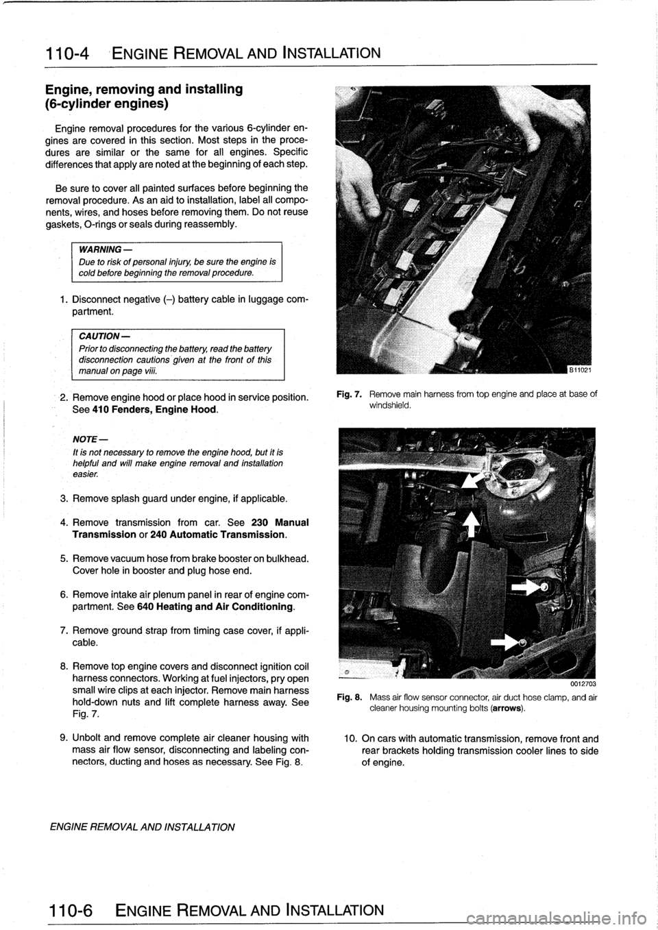
8
.
Remove
top
enginecovers
and
disconnect
ignition
coil
harness
connectors
.
Working
at
fuel
injectors,
pry
open
small
wire
clipsat
each
injector
.
Remove
main
harness
hold-down
nuts
and
lift
completeharness
away
.
See
Fig
.
7
.
ENGINE
REMOVAL
AND
INSTALLATION
Fig
.
7
.
Remove
mainharnessfrom
top
engine
and
place
at
base
of
windshield
.
0012703
Fig
.
8
.
Mass
air
flow
sensor
connector
air
duct
hose
clamp,
and
air
cleaner
housing
mounting
bolts
(arrows)
.
9
.
Unbolt
andremove
complete
air
cleaner
housing
with
10
.
On
cars
with
automatic
transmission,
remove
front
and
mass
air
flow
sensor,
disconnecting
and
labeling
con-
rearbrackets
holding
transmission
cooler
linesto
side
nectors,
ducting
and
hoses
asnecessary
.
See
Fig
.
8
.
of
engine
.
Page 75 of 759
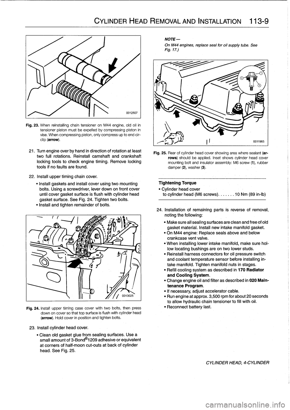
Fig
.
23
.
When
reinstalling
chain
tensioner
on
M44
engine,
old
oil
in
tensioner
piston
mustbe
expelled
bycompressing
piston
in
vise
.
When
compressing
piston,
only
compress
up
to
end
cir-
clip
(arrow)
.
21
.
Turn
engine
overby
hand
in
direction
of
rotation
at
least
two
fui¡
rotations
.
Reinstall
camshaft
and
crankshaft
locking
tools
to
check
engíne
timing
.
Remove
locking
tools
if
no
faults
are
found
.
22
.
Insta¡¡
upper
timingchain
cover
.
"
Install
gaskets
and
instan
cover
using
two
mounting
Tightening
Torque
bolts
.
Using
a
screwdriver,
lever
down
on
front
cover
"
Cylinder
head
cover
until
cover
gasket
surface
is
flush
with
cylinder
head
to
cylinder
head
(M6
screws)
.......
10
Nm
(89
in-lb)
gasket
surface
.
See
Fig
.
24
.
Tighten
two
bolis
.
"
Insta¡¡
and
tighten
remainder
of
bolis
.
23
.
Install
cylinder
head
cover
.
CYLINDER
HEAD
REMOVAL
AND
INSTALLATION
113-
9
0012507
Fig
.
24
.
Install
upper
timing
case
cover
with
two
bolis,
then
press
down
on
cover
so
that
top
surface
is
flush
withcylinder
head
(arrow)
.
Hold
cover
in
position
and
tighten
bolis
.
"
Clean
old
gasket
glue
from
sealing
surfaces
.
Usea
small
amount
of
3-Bond
®
1209
adhesive
or
equivalent
at
corners
of
half-moon
cut-outs
at
back
of
cylinder
head
.
See
Fig
.
25
.
NOTE-
OnM44
engines,
reptace
sea¡
for
oil
supply
tube
.
See
Fig
.
17
.)
Fig
.
25
.
Rear
of
cylinder
head
cover
showing
area
where
sealant
(ar-
rows)
should
be
applied
.
Inset
shows
cylinder
head
cover
mounting
bolt
and
insulator
assembly
:
M6
screw
(1),
rubber
damper
(2),
washer
(3)
.
24
.
Installation
of
remaining
parts
is
reverseofremoval,
noting
the
following
:
"
Make
sure
al¡
sealing
surfaces
are
clean
and
free
of
old
gasket
material
.
Install
new
intake
manifold
gasket
.
"
On
M44
engine
:
Replace
seals
above
and
below
crankcase
ventvalve
.
"
When
installing
lower
intake
manifold,
make
sure
hol-
low
locating
bushings
are
on
two
lower
studs
.
"
Reinstall
harness
connectors
for
oil
pressure
switch
and
coolant
temperature
sensor
before
installing
in-
take
manifold
.
Tighten
manifold
nuts
in
stages
.
"
Refill
cooling
system
as
described
in
170
Radiator
and
Cooling
System
.
"
Change
engine
oil
and
filter
as
described
in
020
Main-
tenance
Program
.
"
If
necessary,
adjust
accelerator
cable
.
"
Run
engine
at
approx
.
3,500
rpm
for
about
20
seconds
to
allow
hydraulic
chain
tensioner
to
fill
with
oil
.
"
Reconnect
battery
last
.
CYLINDER
HEAD,-CYLINDER
Page 102 of 759
117-
6
CAMSHAFT
TIMING
CHAIN
15
.
Insta¡¡
upper
timing
chaincover
:
17
.
Remove
crankshaft
locking
tool
from
transmission
bell-
"
Thoroughly
clean
profile
gasketgroove
and
all
sealing
housing
and
camshaft
locking
tool
from
rear
of
cylinder
surfaces
.
head
.
"
Applya
small
bead
ofsilicon
sealer
(3-Bond
1209®
or
equivalent)
to
upper
and
lower
joint
comers
where
18
.
Turn
engine
over
by
hand
in
direction
of
rotation
at
least
chaincover
meets
cylinder
head
.
two
full
rotations
.
Reinstall
camshaft
and
crankshaft
"
Insta¡¡
new
profile
gasket
to
groove
in
lowerchain
cover
.
locking
tools
to
check
engine
timing
.
Repeat
cam
timing
"
Protect
top
of
profile
gasket
using
thin
sheetmetal
procedure
if
tools
do
not
fit
easily
into
position
.
Remove
(BMW
special
tool
no
.
11
2
330
or
equivalent)
.
See
locking
tools
.
Fig
.
15
.
"
Attach
new
gaskets
to
cover
with
light
dabs
of
gasket
19
.
Install
cylinder
head
cover
as
described
in
113
Cylin-
sealant,
hold
gaskets
in
placeusing
cover
mounting
der
HeadRemoval
and
Installation
.
screws
.
"
Place
upper
timing
cover
into
position
.
Snug
down
al¡
NOTE-
screws,
without
tightening
.
Carefully
slide
out
sheet
OnM44
engines,
note
oil
supply
O-ring
and
replace
ff
metal
.
necessary
.
"
Temporarily
install
cylinder
head
cover
without
gasket
.
Insta¡¡
and
tighten
at
least
two
cylinder
head
cover
mounting
bolts
to
seat
upper
timing
chaincover
.
"
Tighten
all
upper
timing
cover
screws
.
Tightening
Torque
"
Remove
valve
cover
.
"
Cylinder
head
cover
to
cylinder
head
(M6
screws)
...
..
.
.
10
Nm
(89
ín-Ib)
-
CAMSHAFT
TIMING
CHAINS,
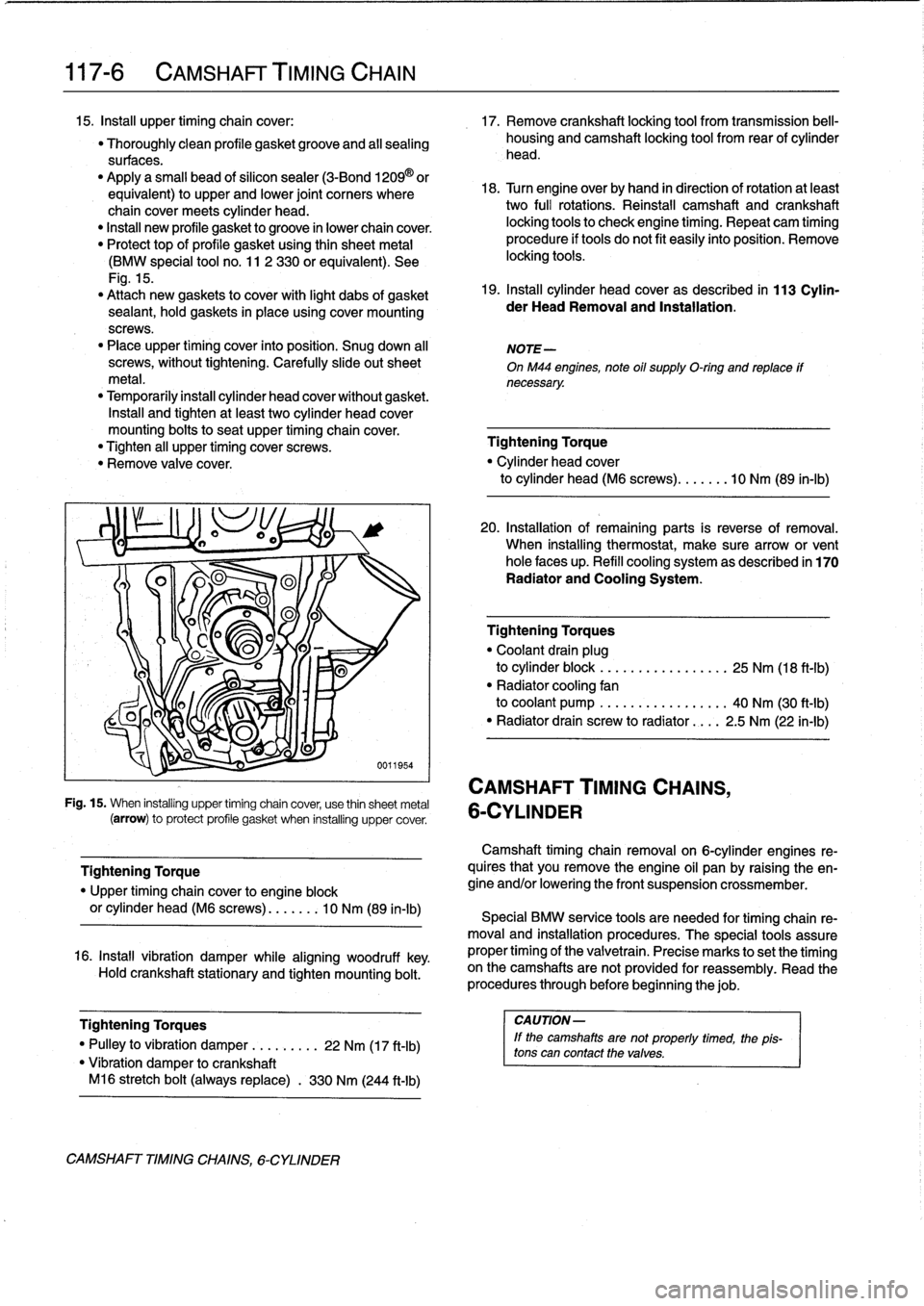
Fig
.
15
.
When
installing
upper
timing
chain
cover,
use
thin
sheetmetal
6-CYLINDER
(arrow)
to
protect
profile
gasket
when
installing
uppercover
.
Tightening
Torque
"
Upper
timing
chaincover
to
engine
block
or
cylinder
head
(M6
screws)
....
.
..
10
Nm
(89
in-lb)
16
.
Install
vibration
damper
while
aligning
woodruff
key
.
Hold
crankshaft
stationary
and
tighten
mounting
bolt
.
Tightening
Torques
I
CAUTION-
"
Pulley
to
vibration
damper
..
.
.
.
....
22
Nm
(17
ft-Ib)
lf
the
camshaftsare
not
properly
timed,
the
1
pis-
tons
can
contact
thevalves
.
"
Vibration
damper
tocrankshaft
M16
stretch
bolt
(always
replace)
.
330
Nm
(244
ft-Ib)
CAMSHAFT
TIMINGCHAINS,
6-CYLINDER
20
.
Installation
of
remaining
parts
is
reverse
of
removal
.
When
installing
thermostat,
make
sure
arrow
or
vent
hole
faces
up
.
Refill
cooling
system
as
described
in
170
Radiator
and
Cooling
System
.
Tighteníng
Torques
"
Coolant
drain
plug
to
cylinder
block
.
..
.
.
.
...
.
..
.....
25
Nm
(18
ft-Ib)
"
Radiator
cooling
fan
to
coolant
pump
.
..
.
...
...
..
.....
40
Nm
(30
ft-Ib)
"
Radiator
drain
screw
to
radiator
....
2
.5
Nm
(22
in-lb)
Camshaft
timing
chainremovalon
6-cylinder
engines
re-
quires
that
you
Rmove
the
engine
oil
pan
by
raising
the
en-
gine
and/or
lowering
the
front
suspension
crossmember
.
Special
BMW
service
tools
are
needed
for
timing
chain
re-
moval
and
installation
procedures
.
The
special
tools
assure
proper
timing
of
the
valvetrain
.
Precise
marks
to
setthe
timing
on
the
camshafts
arenot
provided
for
reassembly
.
Read
the
procedures
through
before
beginning
thejob
.
Page 107 of 759
9)
B11126
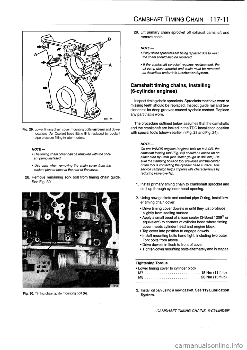
Fig
.
29
.
Lower
timing
chain
cover
mounting
bolts
(arrows)
anddowel
locations
(A)
.
Coolant
hose
fitting
B
is
replaced
by
coolant
pipe
pressure
fitting
in
later
models
.
28
.
Remove
remaining
Torx
bolt
from
timing
chain
guide
.
See
Fig
.
30
.
Fig
.
30
.
Timing
chainguide
mounting
bolt(A)
.
CAMSHAFT
TIMING
CHAIN
117-
11
29
.
Lift
primary
chain
sprocket
off
exhaust
camshaft
and
remove
chain
.
NOTE-
"
If
any
of
the
sprockets
are
being
replaced
due
to
wear,
the
chain
should
also
be
replaced
.
"
If
the
crankshaft
sprocket
requires
replacement,
the
oil
pump
drive
sprocket
and
chain
must
be
removed
as
described
under
119
Lubrication
System
.
Camshaft
timing
chains,
installing
(6-cylinder
engines)
Inspecttiming
chainsprockets
.
Sprockets
that
haveworn
or
missing
teeth
should
be
replaced
.
Inspect
guide
rail
and
ten-
sioner
rail
for
deep
grooves
caused
by
chain
contact
.
Replace
any
parí
that
is
worn
.
The
procedure
outlined
below
assumes
that
the
camshafts
and
the
crankshaft
are
locked
in
the
TDC
installation
position
with
special
tools
(shown
earlier
in
Fig
.
23
and
Fig
.
24)
.
NOTE-
NOTE-
On
pre-VANOS
engines
(engines
built
up
to
8-92),
the
"
The
timing
chain
cover
can
be
removed
with
the
cool-
camshaft
locking
tool
(Fig
.
24)should
be
raised
upon
ant
pump
installed
.
eitherside
by
3mm
(use
feeler
gauge
or
dril¡
bits)
.
Be
sure
the
clamping
bolts
on
tool
are
loose
and
thecenter
"
Use
care
when
removing
the
chain
cover
from
the
of
the
tool
is
contacting
the
cylinder
head
surface
.
This
coolant
pipe
or
hose
at
the
rearof
the
cover
.
service
campaign
helps
improve
idle
characteristics
by
reducing
valve
overlap
.
1
.
Install
primary
timing
chain
to
crankshaft
sprocket
and
tie
it
up
through
cylinder
head
opening
.
2
.
Using
new
gaskets
and
coolant
pipe
O-ring
;
insta¡¡
low-
ertiming
chain
cover
:
"
Drive
timing
cover
doweis
inuntil
they
just
protrude
slightly
from
sealing
surface
.
"
Apply
a
small
bead
of
silicon
sealer
(3-Bond
1209
©
or
equivalent)
to
corners
of
cylinder
head
where
timing
cover
meets
cylinder
head
and
engine
block
.
"
Tap
cover
into
position
to
engage
doweis
.
"
Install
mounting
bolts
hand
tight,
including
two
outer
Torx
bolts
from
above
.
"
Drive
doweis
in
flush
to
front
of
cover
.
"
Tighten
cover
mounting
bolts
alternately
and
in
stages
.
Tightening
Torque
"
Lower
timing
cover
to
cylinder
block
M7
................
...
..
.
.....
15
Nm
(11
ft-Ib)
M8
.............
.
.
...
.........
20
Nm
(15
ft-Ib)
3
.
Insta¡¡
oil
pan
using
a
new
gasket
.
See
119
Lubrication
Systern
.
CAMSHAFT
TIMINGCHAINS,
6-CYLINDER
Page 112 of 759
117-
1
6
CAMSHAFT
TIMING
CHAIN
15
.
Remove
crankshaft
locking
tool
.
Remove
special
test
equipment
.
Insta¡¡
oil
supply
line
using
new
seals
and
reconnect
solenoid
connector
.
Remainder
of
installa-
tion
is
reverse
of
removal
.
Tightening
Torque
"
Cylinder
head
cover
to
cylinder
head
.
10
Nm
(89
in-lb)
"
VANOS
oil
supply
line
to
VANOS
control
unit
(banjo
bolt)
..
.........
32
Nm
(24
ft-Ib)
"
VANOS
solenoidlo
VANOS
control
unit
........
.
.
.
..
........
30
Nm
(22
ft-Ib)
VANOS
control
unit,
removing
Special
BMW
service
tools
are
required
lo
remove
and
in-
stall
the
VANOS
control
unit
.
Read
the
procedure
through
be-
forestarting
the
job
.
1
.
Remove
radiator
cooling
fan
shroud
and
cooling
fan
.
See
170
Radiator
and
Cooling
System
.
CAUTION-
Radiator
fan
has
left
hand
threads
.
2
.
Remove
top
plastic
engine
covers
.
Disconnect
ignition
coil
harness
connectors
from
coils
.
Remove
ignition
coils
.
Remove
cylinder
head
cover
.
Unclip
andremove
oil
baffle
cover
from
above
intake
camshaft
.See
113
Cylinder
Head
Removal
and
Installation
.
NOTE-
Make
note
of
the
mounting
bolt
insulator
arrangement
during
removal
of
the
cylinder
head
cover
.
3
.
Set
engine
lo
TDC
by
rotating
engine
in
normal
operat-
ing
direction
until
camshaft
lobes
at
cylinder
no
.
1
are
facing
each
other
and
"0/T"
mark
(0°TDC)
on
vibration
damper
lines
up
with
cast
boss
on
lower
timing
chain
cover
.
See
Fig
.
38
.
4
.
Lock
crankshaft
at
TDC
by
inserting
BMW
special
tool
no
.
11
2
300
through
transmission
bellhousing
and
finto
flywheel
or
drive
plate
.
Refer
to
Fig
.
36
given
earlier
.
NOTE-
Confirm
that
the
locking
tool
has
been
correctly
in-
stalled
by
trying
to
rotatethe
crankshaft
.
5
.
Remove
three
cylinder
head
cover
mounting
studs
from
rear
of
head
.
Lockcamshafts
at
TDC
bymounting
BMW
special
tool
no
.
11
3
240
at
ends
of
camshafts
.
Check
that
tool
is
squarely
seated
on
cylinder
head
gasket
surface
.
If
necessary,
rotate
camshafts
slightly
using
a24
mm
wrench
.
Refer
to
Fig
.
24
given
earlier
.
VANOS
(VARIABLE
VALVE
TIMING)
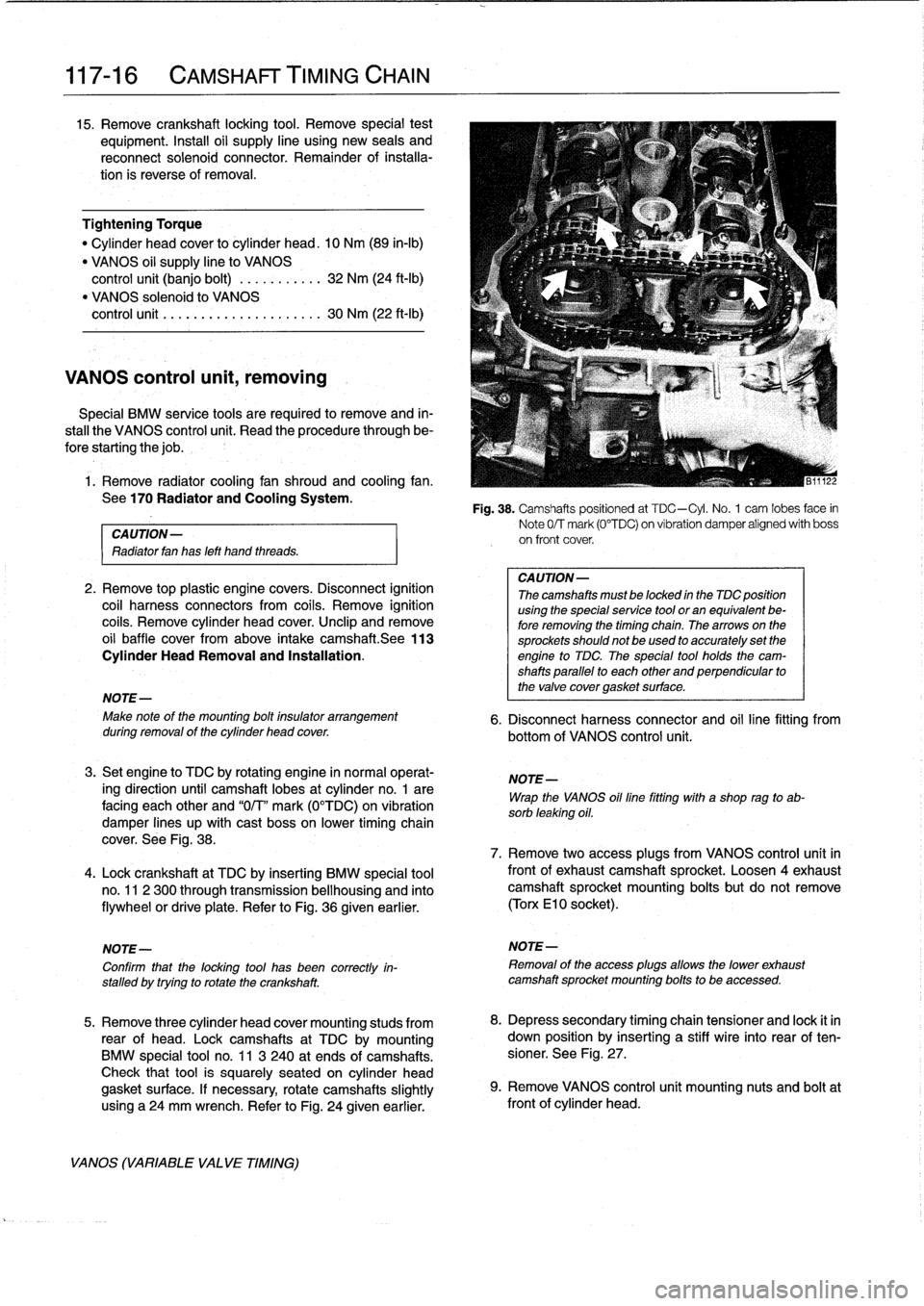
Fig
.
38
.
Camshafts
positioned
at
TDC-Cyl
.
No
.
1
cam
lobes
face
in
Note
0/T
mark
(0°TDC)
on
vibration
damper
alígned
with
boss
on
front
cover
.
CA
UTION-
Thecamshafts
mustbe
locked
in
the
TDC
position
using
the
specialservice
tool
or
an
equivalent
be-
fore
removing
the
timing
chain
.
Thearrows
on
the
sprockets
should
not
be
used
to
accurately
set
the
engine
to
TDC
The
special
tool
holds
the
cam-
shafts
parallel
to
each
other
and
perpendicular
to
the
valve
cover
gasket
surface
.
6
.
Disconnect
harness
connector
and
oil
line
fitting
from
bottom
of
VANOS
control
unit
.
NOTE-
Wrap
the
VANOS
oilfine
fitting
with
a
shop
rag
to
ab-
sorb
leaking
oil
.
7
.
Remove
two
access
plugs
from
VANOS
control
unit
in
frontof
exhaustcamshaft
sprocket
.
Loosen
4exhaustcamshaft
sprocket
mounting
bolts
but
do
not
remove
(Torx
El
0
socket)
.
NOTE-
Removal
of
the
access
plugs
allows
the
lower
exhaust
camshaft
sprocket
mounting
bolts
to
be
accessed
.
8
.
Depress
secondary
timing
chain
tensioner
and
lock
it
in
down
position
by
inserting
a
stiff
wire
into
rear
of
ten-
sioner
.
See
Fig
.
27
.
9
.
Remove
VANOS
control
unít
mounting
nuts
and
boltat
front
of
cylinder
head
.
Page 114 of 759
117-
1
8
CAMSHAFT
TIMING
CHAIN
CAUTION-
It
is
crítical
that
the
exhaustcamshaft
sprocket
be
turned
only
the
mínimum
amount
necessary
to
engage
the
gear
cup
.
If
this
procedure
is
done
ín-
correctly,
the
VANOS
system
may
not
function
throughout
íts
full
range
.
NOTE-
As
the
control
unit
isinstalled,
the
secondary
sprockets
will
rotate
in
the
counterclockwise
direction
.
It
may
be
necessary
to
guide
sprockets
counterclockwise
as
the
control
unit
is
installed
.
8
.
On
cars
built
from3/95
:
Use
a
spanner
tool
(See
Fig
.
39
.),
turn
exhaust
sprocket
counterclockwise
(as
víewed
from
front
of
engine)
only
enough
to
mesh
gear
cup
splines
with
camshaftgear
.
Slowly
push
VANOS
control
unit
towards
camshaft
until
it
is
fully
seated,guiding
chains
in
counterclockwise
direction
.
CA
UTION-
Ensure
that
the
first
available
tooth
engages
.
9
.
Install
and
tightencontrol
unit
nuts
and
bolt
.
10
.
Connect
harness
connector
to
VANOS
solenoid
.
Using
new
seals,
insta¡¡
oil
line
fitting
.
Tightening
Torques
"
VANOS
control
unitto
cylinder
head
M6
nut
.....
..
..
.
.
.............
10
Nm
(89
in-lb)
M8
bolt
.....
.
.
.
.
..
.............
22
Nm
(17
ft-Ib)
"
VANOS
oil
supply
line
to
control
unit
.
32
Nm
(24
ft-Ib)
11
.
Slowlyunlock
and
release
secondary
chain
tensioner
.
12
.
Preloadprimary
chain
by
tightening
BMW
special
tool
no
.
112
240
(dummy
chain
tensioner)
to
1
.3
Nm
(11
in-
lb)
.
Then
tighten
exhaust
camshaft
sprocket
mounting
bolts
alternately
in
two
stages
.
Tightening
Torque
"
Secondarytiming
chain
sprockets
to
camshafts
(Tora
boits)
Stage
1
..
...............
...
.
.
...
5
Nm
(44
in-lb)
Stage
2
..
...............
...
.
.
..
22
Nm
(17
ft-Ib)
VANOS
(VARIABLE
VALVE
TIMING)
13
.
Remove
flywheel
locking
tool
from
transmission
bell-
housing
.
Remove
camshaft
locking
tool
from
rear
of
cylinder
head
.
14
.
Turn
engine
over
by
hand
at
least
two
fui¡
crankshaft
ro-
tations
.
Reinstall
camshaft
locking
tool
and
flywheel
locking
toolto
make
sure
all
adjustments
are
correct
.
If
settings
are
correct,
remove
locking
tools
.
15
.
Remove
BMW
special
tool
112
420
(dummy
chain
ten-
sioner)
from
side
of
cylinder
head
.
Install
primary
chain
tensioner
so
that
cutout
in
tensioner
piston
engages
chain
rail
.
See
Fig
.
34
.
Using
new
seals,
install
and
tighten
access
plugs
in
VANOS
control
unit
.
Tightening
Torque
"
Access
plugs
to
VANOS
control
unit
.
..
.
.....
.
..
...
50
Nm
(37
ft-lb)
"
Primary
timing
chain
tensioner
plug
to
tensioner
sleeve
M50/S50USengine
.
.
..
.
.
...
.
...
..
50
Nm
(37
ft-Ib)
M52/S52US
engine
...
..
...
...
...
40
Nm
(30
ft-Ib)
16
.
Install
oil
baffle
cover
above
intake
camshaft
.
Install
three
cylinder
head
covermounting
studs
to
rear
of
head
.
Instali
cylinder
head
cover
.
Tightening
Torque
"
Cylinder
head
cover
to
cylinder
head
(M6
screws)
......
10
Nm
(89
in-Ib)
17
.
Installationof
remaining
parts
is
reverse
of
removal
.
NOTE-
Be
sure
to
install
the
ground
wíres
at
the
cylinder
head
cover
mounting
studs
and
at
the
front
of
the
cylinder
head,
if
applicable
.
Page 118 of 759
119-
4
LUBRICATION
SYSTEM
15
.
Remove
oil
pan
screws
.
Lower
andremove
oil
pan
to-
ward
rear
.
Tightening
Torques
"
Control
arm
bushing
carrier
CAUTION-
to
body(M10
bolt)
...............
42
Nm
(31
ft-Ib)
'
lf
the
oil
pan
does
not
separate
easily
from
the
en-
"
Engine
mount
to
gine
cylinder
block,
make
sure
all
mounting
bolis
suspension
crossmember
(M10
nut)
.
42
Nm
(31
ft-Ib)
have
been
removed
.
If
necessary,
a
few
tapswith
"
Front
suspension
crossmember
a
rubber
mallet
shouldbreak
it
free
.
Never
pry
the
to
body
.
.
..
...
..
.
....
See
310
Front
SusPension
oil
pan
loose
.
"
Oil
pan
to
engine
block
(M6
bolt)
8
.8
grade
..
....
.
...
...
.
........
10
Nm
(89
in-lb)
16
.
Installation
is
reverse
of
removal
.
10
.9
grade
...
..
.
....
..
.
.
.
.......
12
Nm
(9
ft-Ib)
"
Thoroughly
clean
all
old
gasket
material
from
mating
"
Power
steering
pump
to
bracket
surfaces
anduse
a
new
gasket
.
(self-locking
nuts)
....
..
.
....
..
.
..
22
Nm
(16
ft-Ib)
"
Applya
small
amount
of
non-hardening
sealer
(3-
"
Power
steering
pump
bracket
to
engine
Bond
O
l209
or
equivalent)
to
oil
pan
gasket
directly
block
or
oil
pan
(self-locking
nuts)
..
.
22
Nm
(16
ft-Ib)
below
joints
for
end
cover
and
front
timing
case
cover
.
"
Stabilizer
bar
link
to
control
arm
See
Fig
.
5
.
M8
nut
.................
...
.
...
22
Nm
(17
ft-Ib)
"
When
installing
oil
pan
to
engine,
tighten
forward
M10
nut
.....................
..
42
Nm
(31
Ib-ft)
screws
first,
then
tightenrear
.
"
Steering
column
universal
joint
"
Fill
engine
with
oil
as
described
in
020
Maintenance
to
steering
rack
spindle
(M8
bolt)
....
19
Nm
(14
ft-ib)
Program
.
0011950
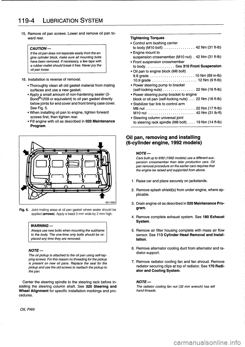
Fig
.
5
.
Joint-mating
areas
at
oil
pan
gasket
where
sealer
should
be
applied
(arrows)
.
Apply
a
bead
3
mm
wideby
2
mm
high
.
OIL
PAN
WARNING
-
Always
use
new
bolis
when
mounting
the
subframe
to
the
body
.
The
one-timeonly
bolis
shouldbe
re-
placed
any
timethey
are
removed
.
NOTE-
The
oil
pickup
is
attached
to
the
oil
pan
using
self-tap-
ping
screws
.
For
this
reasonno
threading
for
the
pickup
is
present
on
new
oil
pans
.
Replace
the
seal
for
the
pickup
and
use
the
oíd
screws
to
rea
ttach
the
pickup
to
the
pan
.
Oil
pan,
removing
and
installing
(6-cylinder
engine,
1992models)
NOTE-
Cars
built
up
to
9/92
(1992models)usea
different
sus-
pension
crossmember
than
later
production
cars
.
Oil
pan
removalprocedureon
the
earlier
cars
requires
that
the
engine
be
raised
and
supportedfrom
above
.
1
.
Raise
car
and
place
securely
on
jackstands
.
2
.
Remove
splash
shield(s)
from
under
engine,
where
ap-
plicable
.
3
.
Drain
engine
oil
as
described
in
020
Maintenance
Pro-
gram
.
4
.
Remove
complete
exhaust
system
.
See180
Exhaust
System
.
5
.
Remove
air
filter
housing
complete
with
mass
air
flow
sensor
.
See
113
Cylinder
Head
Removal
and
Instal-
lation
.
6
.
Remove
alternator
cooling
duct
from
alternator
and
ra-
diator
support
.
7
.
Remove
radiator
cooling
fan
and
fan
shroud
.
Remove
radiator
securing
clips
at
top
of
radiator
.
See
170
Radi-
ator
and
Cooling
System
.
Center
the
steering
spindle
to
the
steering
rack
before
in-
NOTE-
stalling
the
steering
column
shaft
.
See
320
Steering
and
The
radiator
cooling
fan
nut(32
mm
wrench)
has
left
Wheel
Alignment
for
specific
installation
markings
and
pro-
hand
threads
.
cedures
.