torque BMW M3 1995 E36 User Guide
[x] Cancel search | Manufacturer: BMW, Model Year: 1995, Model line: M3, Model: BMW M3 1995 E36Pages: 759
Page 35 of 759
Accelerator
and
Throttle
Linkage
The
accelerator
and
throttie
linkage
should
be
lubricated
pe-
riodically
.
Use
a
general
purpose
oil
on
the
joints
and
bearings
of
the
linkage
.
Use
a
multipurpose
grease
on
the
bearing
points
of
the
throttie
plate
.
Engine
Drive
Belts
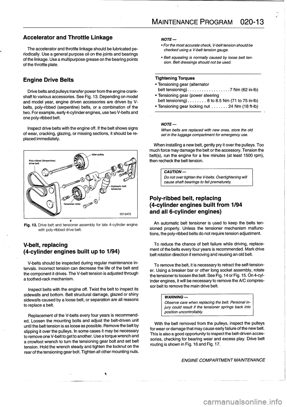
Drive
belts
and
pulleys
transfer
power
from
theengine
crank-
shaft
to
various
accessories
.
See
Fig
.
13
.
Depending
on
model
and
model
year,
engine
driven
accessories
are
driven
by
V-
belts,
poly-ribbed
(serpentine)
belts,
or
a
combination
of
the
two
.
For
example,
early
4-cylinder
engines,
usetwo
V-belts
and
one
poly-ribbed
belt
.
Inspect
drivebelts
with
the
engine
off
.
lf
the
belt
shows
signs
of
wear,
cracking,
glazing,
or
missing
sections,
it
should
be
re-
placed
immediately
.
V
belt,
replacing
(4-cylinder
engines
built
up
to
1194)
0012472
Fig
.
13
.
Drive
belt
and
tensioner
assembly
for
late
4-cylinder
engine
wíth
poly-ribbed
drive
belt
.
V-belts
should
be
inspected
during
regular
maintenance
in-
tervais
.
Incorrect
tension
can
decrease
the
life
of
the
belt
and
the
component
it
drives
.
The
V-belt
tension
is
adjusted
through
a
toothed-rack
mechanism
.
Inspect
belts
with
the
engine
off
.
Twist
the
beltto
inspect
its
sidewalls
and
bottom
.
Beltstructural
damage,
glazed
or
shiny
sidewaljs
caused
by
a
loose
belt,
orseparation
are
al¡
reasons
to
replace
a
belt
.
Replacement
of
the
V-belts
every
four
years
is
recommend-
ed
.
Loosen
the
mounting
bolts
and
adjust
the
belt-driven
unit
until
the
belt
tension
is
as
loose
aspossible
.
Remove
the
belt
by
slipping
it
over
the
pulleys
.
In
some
cases
it
may
be
necessary
to
removeone
V-belt
to
get
to
another
.
Use
a
torque
wrench
and
a
crowfoot
wrench
to
turn
the
tensioning
gear
bolt
and
set
belt
tension
.
Hold
the
wrench
steady
and
tighten
the
locknut
on
the
rear
of
the
tensioning
gear
bolt
.
Tighten
al¡
other
mounting
nuts
.
MAINTENANCE
PROGRAM
020-
1
3
NOTE-
"
For
the
most
accurate
check,
V-belt
tension
should
be
checked
using
a
V-belt
tension
gauge
.
"
Belt
squealing
is
normally
caused
by
loose
beltten-sion
.
Belt
dressings
should
not
be
used
.
Tightening
Torques
"
Tensioning
gear
(alternator
belt
tensioning)
.
.
.
...............
7
Nm
(62
in-lb)
"
Tensioning
gear(power
steering
belt
tensioning)
...
..
...
8
to
8
.5
Nm
(71
to
75
in-lb)
"
Tensioning
gear
locking
nut
.......
24
Nm
(18
ft-Ib)
NOTE-
When
belts
are
replaced
with
new
ones,
store
the
old
set
in
the
luggage
compartment
for
emergency
use
.
When
installing
a
new
belt,
gently
pry
it
over
the
pulleys
.
Too
much
force
may
damage
the
belt
or
the
accessory
.
Tension
the
belt(s),
runthe
engine
for
a
few
minutes
(at
least
1500
rpm),
then
recheck
the
belt
tension
.
CAUTION-
Do
not
over
tighten
the
V-belts
.
Overtightening
will
cause
shaft
bearings
to
fail
prematurely
.
Poly-ribbed
belt,
replacing
(4-cylinder
engines
buiit
from
1194
and
all
6-cylinder
engines)
An
automatic
belt
tensioner
is
used
to
keep
the
belts
ten-
sioned
properly
.
Unless
the
tensioner
mechanism
malfunc-
tions,
the
poly-ribbed
belts
do
not
require
tension
adjustment
.
To
reduce
the
chance
ofbelt
failure
while
driving,
replace-
ment
of
the
belts
every
four
years
is
recommended
.
Mark
drive
belt
rotationdirectíon
if
removing
and
reusing
an
old
belt
.
To
remove
the
belt,
it
is
necessary
toretract
the
self-tension-
er
.
Using
a
breaker
bar
or
other
long
socket
assembly,
rotate
the
tensioner
to
loosenthe
belt
.
See
Fig
.
14
or
Fig
.
15
.
On
4-cyl-
inder
engines,
it
will
benecessary
to
remove
the
A/C
compres-
sor
belt
to
remove
the
main
drive
belt
.
WARNING
-
Observe
care
when
replacing
the
belt
.
Personal
in-
jury
could
result
if
the
tensioner
springs
back
into
position
uncontrollably
.
With
the
belt
removed
from
the
pulleys,
inspect
the
pulleys
for
wear
or
damage
that
may
cause
early
failureof
the
new
belt
.
This
is
also
a
good
opportunity
to
inspect
the
belt-driven
acces-
sories,
checking
for
bearing
wear
and
excess
play
.
Drive
belt
routing
is
shown
in
Fig
.
16
and
Fig
.
17
.
ENGINE
COMPARTMENT
MAINTENANCE
Page 37 of 759
Fig
.
18
.
Fill
mark
on
coolant
expansion
tank
.
Coolant
level
should
be
at
mark
when
engine
ís
cold
.
.
..
e
..
.-
..
~
..
.-
.
Ozone
Damaged
Hose
0012476
Fig
.
19
.
Examples
of
damage
to
coolant
hoses
.
Any
of
conditions
shown
is
cause
for
replacement
.
Courtesy
of
Gates
Rubber
Company,
Inc
.
Specification
"
Power
steering
fluid
..........
.
...
Dexron
III®ATF
Oxygen
Sensors
1996
and
later
engines
are
equipped
withmultiple
oxygen
sensors
.
See
Fig
.
21
.
A
regulating
sensor
is
mounted
before
each
catalytic
converter
and
amonitoring
sensor
downstream
of
each
converter
.
The
regulating
sensor
monitors
engine
com-
bustion
efficiency
and
helps
to
control
the
fuel
injection
system
and
exhaust
emissions
.
The
monitoring
sensor
is
usedby
the
On-board
diagnostic
system
to
monitor
the
function
of
the
cata-
lytic
converter
.
MAINTENANCE
PROGRAM
020-
1
5
NOTE-
5pecialsockets
for
replacingthe
oxygen
sensor
are
available
from
most
automotive
parts
stores
.
The
sock-
et
has
agroove
cut
down
one
side
to
allow
the
sensor
to
be
installed
without
damaging
the
wire
hamess
.
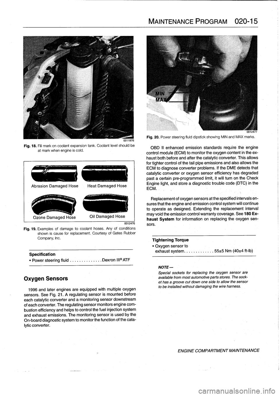
Fig
.
20
.
Power
steering
fluid
dipstick
showing
MIN
and
MAX
marks
.
OBD
II
enhanced
emission
standards
require
the
engine
control
module
(ECM)
to
monitor
the
oxygen
content
in
theex-
haust
bothbefore
and
after
the
catalytic
converter
.
This
allows
for
tightercontrol
of
the
tail
pipe
emissions
and
also
allowsthe
ECM
to
diagnose
converter
problems
.
lf
the
DME
detects
that
catalytic
converter
or
oxygen
sensor
efficiency
has
degraded
past
a
certain
pre-programmed
limit,
it
will
turn
on
the
Check
Engine
light,
and
store
a
diagnostic
trouble
code
(DTC)
in
the
ECM
.
Replacement
of
oxygen
sensors
at
the
specified
intervals
en-
sures
that
the
engine
and
emission
control
system
wíll
continue
to
operate
as
designed
.
Extending
the
replacement
interval
may
void
the
emission
control
warranty
coverage
.
See
180
Ex-
haust
System
for
information
on
replacing
the
oxygen
sen-
sors
.
Tightening
Torque
"
Oxygen
sensor
to
exhaust
system
........
.
.
.
..
55±5
Nm
(40±4
ft-Ib)
ENGINE
COMPARTMENT
MAINTENANCE
Page 40 of 759
020-
1
8
MAINTENANCE
PROGRAM
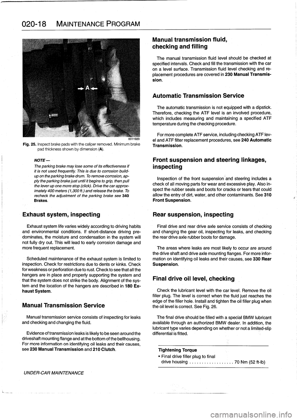
Fig
.
25
.
Inspect
brake
pads
with
the
caliper
removed
.
Minimum
brake
pad
thickness
shown
by
dimension
(A)
.
NOTE-
The
parking
brake
may
lose
some
of
its
effectiveness
if
it
is
not
used
frequently
.
This
is
due
to
corrosion
build-
up
on
the
parking
brake
drum
.
To
remove
corrosion,
ap-
plythe
parking
brake
just
until
it
begins
togrip,
then
pulí
the
lever
up
one
more
stop
(click)
.
Drive
thecar
approx-
imately
400
meters
(1,300
ft
.)
and
release
the
brake
.
To
recheck
the
adjustment
of
the
parking
brake
see340
Brakes
.
UNDER-CAR
MAINTENANCE
0011920
Manual
transmission
fluid,
checking
and
filling
The
manual
transmission
fluid
leve¡
should
be
checked
at
specified
intervals
.
Check
and
fill
the
transmission
with
the
car
ona
leve¡
surface
.
Transmission
(luid
leve¡
checking
and
re-
placement
procedures
are
covered
in
230
Manual
Transmis-
sion
.
Automatic
Transmission
Service
The
automatic
transmission
is
not
equipped
with
a
dipstíck
.
Therefore,
checking
the
ATF
level
is
an
ínvolved
procedure,
which
includes
measuring
and
maintaining
a
specified
ATF
temperature
during
the
checking
procedure
.
For
more
complete
ATF
service,
including
checking
ATF
lev-
e¡
and
ATF
filter
replacement
procedures,
see
240
Automatic
Transmission
.
Front
suspension
and
steering
linkages,
inspecting
Inspection
of
the
front
suspension'and
steering
includes
a
check
of
all
moving
parts
for
wear
and
excessive
play
.
Also
in-
spect
the
rubber
seals
and
boots
for
cracks
or
tears
that
could
allow
the
entry
of
dirt,
water,
and
other
contaminants
.
See
310
Front
Suspension
.
Exhaust
system,
inspecting
Rear
suspension,
inspecting
Exhaust
system
life
varies
widely
according
to
driving
habits
Final
drive
and
rear
drive
axle
service
consists
of
checking
and
environmental
conditions
.
If
short-distance
driving
pre-
and
changing
the
gear
oil,
inspecting
for
leaks,
and
checking
dominates,
the
moisture
and
condensation
in
the
system
will
the
rear
drive
axle
rubber
boots
for
damage
.
not
fully
dryout
.
This
will
lead
to
early
corrosion
damage
and
more
frequent
replacement
.
The
areas
where
leaks
are
most
likely
to
occur
are
around
the
driveshaft
and
drive
axle
mounting
flanges
.
For
more
infor
Scheduled
maintenance
of
the
exhaust
system
is
limitedlo
mation
on
ídentifying
oil
leaks
and
their
causes,
see330
Rear
inspection
.
Check
for
restrictions
due
to
dents
or
kinks
.
Check
Suspension
.
for
weakness
or
perforation
due
to
rust
.
Check
lo
see
that
all
the
hangers
are
in
place
and
properly
supporting
the
system
and
that
the
system
does
not
strike
the
body
.
Alignment
of
the
sys-
Final
drive
oil
leve¡,
checking
temand
the
location
of
the
hangers
aredescribed
in
180
Ex-
haust
System
.
Check
the
lubricant
leve¡
with
thecar
level
.
Remove
the
oil
filler
plug
.
The
leve¡
is
correct
when
the
fluidjust
reaches
the
edge
of
the
filler
hole
.
Install
and
tighten
the
oil
filler
plug
when
Manual
Transmission
Service
the
oil
level
is
correct
.
See
Fig
.
26
.
Manual
transmissionservice
consists
of
inspectingfor
leaks
The
final
drive
should
be
filled
with
a
special
BMW
lubricant
and
checking
and
changing
the
fluid
.
available
through
an
authorized
BMW
dealer
.
In
addition,
the
lubricant
type
varies
depending
onwhether
or
nota
limited-slip
Evidence
of
transmissionleaks
is
fkely
to
beseenaround
the
differential
is
fitted
.
driveshaft
mounting
flange
and
at
the
bottom
of
the
bellhousing
.
For
more
information
on
identifying
oil
leaks
and
their
causes,
see230ManualTransmissionand210
Clutch
.
Tightening
Torque
"
Finaldrive
filler
plug
to
final
drive
housing
..................
70
Nm
(52
ft-Ib)
Page 44 of 759
100-2
ENGINE-GENERAL
Cylinder
Head
and
Valvetrain
The
aluminum
cylinder
head
uses
chain-driven
double
overhead
camshafts
and
four
valves
per
cylinder
.
See
Fig
.
1
.
The
cylinder
head
employs
a
crossflow
design
for
greater
power
and
efficiency
.
Intake
air
enters
the
combustion
cham-
ber
from
one
side
while
exhaust
gasses
exit
from
the
other
.
Oílways
in
the
head
provide
lubrication
for
the
camshafts)
and
valvetrain
.
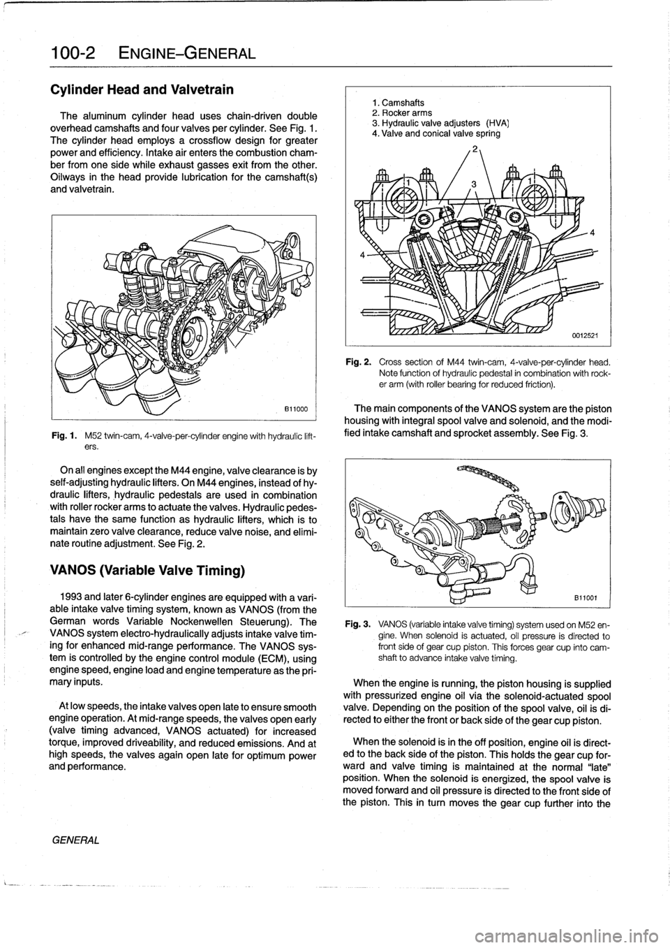
Fig
.
1
.
M52
twin-cam,
4-valve-per-cylinder
engine
with
hydraulíc
lift-
ers
.
On
all
engines
exceptthe
M44
engine,
valveclearance
is
by
seif-adjusting
hydraulic
lifters
.
On
M44
engines,
instead
of
hy-
draulic
lifters,
hydraulic
pedestaisare
used
in
combination
with
roller
rocker
arms
to
actuate
the
valves
.
Hydraulic
pedes-
tals
have
the
same
function
as
hydraulic
lifters,
which
ís
to
maintain
zero
valve
clearance,
reduce
valve
noise,
and
elimí-
nate
routíne
adjustment
.
See
Fig
.
2
.
VANOS
(Variable
Valve
Timing)
GENERAL
1
.
Camshafts
2
.
Rocker
arms
3
.
Hydraulic
valve
adjusters
(HVA)
4
.
Valve
and
conical
valve
spring
4
Fig
.
2
.
Cross
sectionof
M44
twin-cam,
4-valve-per-cylinder
head
.
Note
function
of
hydraulíc
pedestal
in
combination
with
rock-er
arm
(with
roller
bearing
for
reduced
friction)
.
The
main
components
of
the
VANOS
system
arethe
piston
housing
with
integral
spool
valve
and
solenoid,
and
the
modi-
fied
intake
camshaft
and
sprocket
assembly
.
See
Fig
.
3
.
1993
and
later
6-cylinder
engines
are
equipped
with
a
vari-
B11001
able
intake
valve
timing
system,
known
as
VANOS
(from
the
German
words
Variable
Nockenwellen
Steuerung)
.
The
Fig
.
3
.
VANOS
(variable
intake
valve
timing)
systemusedon
M52
en-
VANOS
system
electro-hydraulically
adjusts
intake
valve
tim-
gine
.
When
solenoid
is
actuated,
oíl
pressure
is
directed
to
ingfor
enhanced
mid-range
performance
.
The
VANOS
sys-
front
side
of
gear
cup
piston
.
This
forces
gear
cup
finto
camtem
is
controlled
by
the
engine
control
module
(ECM),
using
shaft
to
advance
intake
valve
timing
.
enginespeed,engine
load
and
engine
temperature
asthe
pri-
mary
inputs
.
When
the
engine
is
running,
the
piston
housing
is
supplied
with
pressurized
engine
oil
víathe
solenoid-actuatedspool
At
low
speeds,
the
intake
valves
open
late
to
ensure
smooth
valve
.
Depending
on
the
position
of
the
spool
valve,
oil
isdi
engine
operation
.
At
mid-rangespeeds,
thevalves
open
early
rected
to
either
the
front
or
back
side
of
the
gear
cup
piston
.
(valvetiming
advanced,
VANOS
actuated)
for
increased
torque,
improved
driveability,
and
reduced
emissions
.
And
at
When
the
solenoid
isin
the
off
position,
engine
oíl
is
direct-
high
speeds,
the
valves
again
open
late
for
optimum
power
ed
to
the
back
side
of
the
piston
.
This
holds
the
gear
cup
for-
and
performance
.
ward
and
valve
timing
is
maintained
at
the
normal
"late"
position
.
When
the
solenoid
is
energized,
the
spoolvalve
is
moved
forward
and
oil
pressure
is
directed
to
the
front
side
of
the
piston
.
This
in
turn
moves
thegear
cup
further
into
the
Page 45 of 759
camshaft
secondary
drive,
causing
thecamshaft
to
"advance"
12
.5°
.
The
helical
gears
are
cut
so
that
forward
motion
of
the
gear
cup
is
transiated
into
rotational
motion
of
the
camshaft
.
See
117
Camshaft
Timing
Chain
for
testing
and
repair
infor-
mation
on
the
VANOS
system
.
DISA
(Dual
Resonance
Intake
System)
DISA,usedon
4-cylinder
engines,
is
a
dual
intake
runner
system
that
effectively
provides
the
advantages
of
both
short
and
long
intake
runners
within
the
same
engine
.
For
best
per-
formance,
long
intake
runners
aremost
beneficial
atlow-
and
mid-engine
speeds
(below
4,200
rpm),
and
short
intake
run-
ners
enhance
torque
at
high
engine
speeds
(above4,200
rpm)
.
NOTE-
The
term
DISA
comes
from
the
German
words
Differ-
enzierte
Sauganlage,
and
can
roughty
be
transiated
as
a
differing
intake
manifold
configuration
.
The
DISA
solenoid
valve
is
controlled
by
the
DME
control
module,
using
engine
speed
as
the
primary
input
.
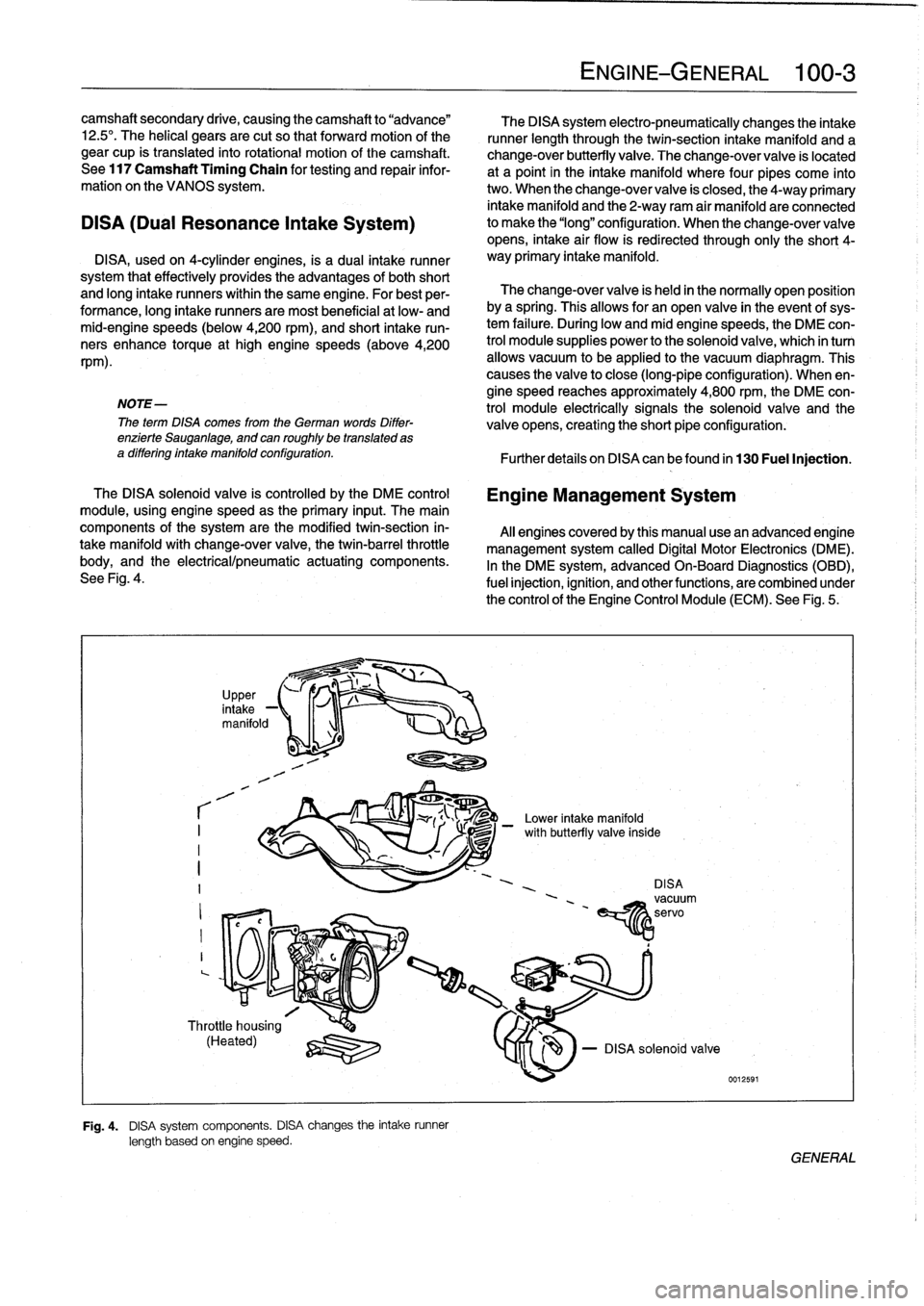
The
main
components
of
the
system
are
the
modified
twin-section
in-
takemanifoldwith
change-over
valve,
the
twin-barrel
throttle
body,
and
the
electrical/pneumatic
actuating
components
.
See
Fig
.
4
.
r
I
I
I
?
,
in
UpPer,
take
-1
manifold
1
-1
Throttle
housing
(Heated)
q
:lZU
Fig
.
4
.
DISA
system
components
.
DISA
changes
the
intake
runner
length
based
on
engine
speed
.
The
DISA
system
electro-pneumatically
changes
the
intake
runner
length
through
the
twin-section
intake
manifold
and
a
change-over
butterfly
valve
.
The
change-over
valve
is
located
at
a
point
in
the
intake
manifold
where
four
pipes
come
into
two
.
When
the
change-over
valve
is
closed,
the
4-way
primary
intake
manifold
and
the
2-way
ram
air
manifold
areconnected
to
make
the
"long"
configuration
.
When
the
change-overvalve
opens,
intake
air
flow
is
redirected
through
only
the
short
4-
way
primary
intake
manifold
.
The
change-over
valve
is
held
in
the
normally
open
position
bya
spring
.
Thisallows
for
an
open
valve
in
the
event
of
sys-
tem
failure
.
During
low
andmid
enginespeeds,
the
DME
con-
trol
module
supplies
power
to
the
solenoid
valve,
which
in
turn
allows
vacuum
to
be
applied
lo
the
vacuum
diaphragm
.
This
causes
the
valve
to
close
(long-pipe
configuration)
.
When
en-
gine
speed
reaches
approximately
4,800
rpm,
the
DME
con-
trol
module
electrically
signals
the
solenoid
valve
and
the
valve
opens,
creating
the
short
pipe
configuration
:
Further
detafs
on
DISA
canbefound
in
130
Fuel
Injection
.
Engine
Management
System
Al¡
enginescoveredby
this
manual
usean
advanced
engine
management
system
called
Digital
Motor
Electronics
(DME)
.
In
the
DME
system,
advancedOn-Board
Diagnostics
(OBD),
fuel
injection,
ignition,
and
otherfunctions,
are
combined
under
the
control
of
theEngine
Control
Module
(ECM)
.
See
Fig
.
5
.
-
Lower
intake
manifold
DISAvacuum
'
~servo
EíY1z
ENGINE-GENERAL
100-
3
le
-
DISA
solenoid
valve
0012591
/
with
butterfly
va¡
GENERAL
Page 49 of 759
eiioo4
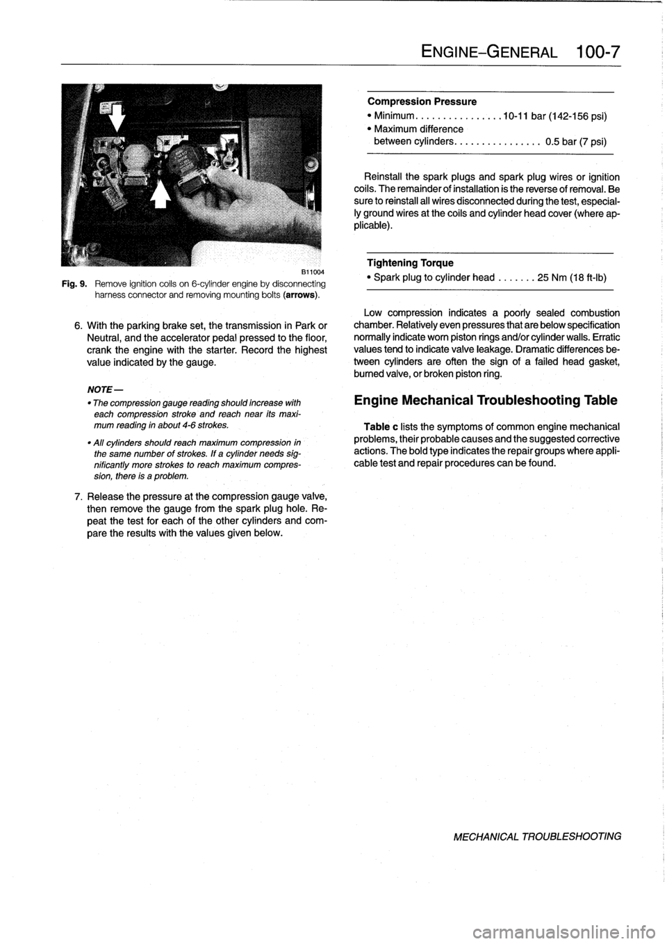
Fig
.
9
.
Remove
ignition
coils
on
6-cylinder
engine
by
disconnecting
harness
connector
and
removing
mounting
bolts
(arrows)
.
NOTE-
"
The
compression
gauge
reading
shoutd
increase
with
each
compression
stroke
and
reach
near
its
maxi-
mum
reading
in
about
4-6
strokes
.
"All
cylinders
shoutdreach
maximum
compression
in
the
same
number
of
strokes
.
If
a
cylinder
needs
sig-
nificantly
more
strokes
to
reach
maximum
compres-
sion,
there
is
a
problem
.
7
.
Release
the
pressure
at
the
compression
gauge
valve,
then
remove
the
gauge
from
the
spark
plughole
.
Re-
peat
the
test
for
each
of
the
other
cylinders
and
com-
pare
the
results
with
the
values
given
below
.
ENGINE-GENERAL
1
:00-
7
Compression
Pressure
"
Minimum
..........
.
.
..
..
10-11
bar
(142-156
psi)
"
Maximum
difference
between
cylinders
..
.....
.........
0
.5
bar
(7
psi)
Reinstall
the
spark
plugs
and
spark
plug
wires
or
ignition
cofs
.
The
remainder
of
installation
is
the
reverse
of
removal
.
Be
sure
to
reihstall
al¡
wires
disconnected
during
the
test,
especial-
¡y
ground
wires
at
the
coils
and
cylinder
head
cover
(where
ap-
plicable)
.
Tightening
Torque
"
Spark
plug
to
cylinder
head
.......
25
Nm
(18
ft-Ib)
Low
compression
indicates
a
poorly
sealed
combustion
6
.
With
the
parking
brake
set,
the
transmission
in
Park
or
chamber
.
Relatively
even
pressures
that
are
below
specification
Neutral,
and
the
accelerator
pedal
pressed
to
the
floor,
normally
indicate
worn
piston
rings
and/or
cylinder
walls
.
Erratic
crank
the
engine
with
the
starter
.
Record
the
highest
values
tend
to
indicate
valve
leakage
.
Dramatic
differences
be
value
indicated
by
the
gauge
.
tween
cylinders
are
often
the
sign
of
a
failed
head
gasket,
bumed
valve,
or
broken
piston
ring
.
Engine
Mechanical
Troubleshooting
Table
Table
c
lists
the
symptoms
of
common
engine
mechanical
problems,
their
probable
causes
and
the
suggested
corrective
actions
.
The
bold
type
indicates
the
repair
groups
where
appli-
cable
test
and
repair
procedures
can
befound
.
MECHANICAL
TROUBLESHOOTING
Page 61 of 759
14
.
Unbolt
power
steering
fluid
reservoir
from
íts
mounting
bracket
.
Use
stiff
wire
to
hang
reservoir
to
one
side
.
Do
not
disconnect
fluid
lines
.
15
.
Remove
power
steering
pump
drive
belt
and
remove
pump
from
its
mounting
bracket
.
Use
stiff
wire
to
hang
pump
from
body
.
16
.
On
cars
with
automatic
transmission
remove
front
and
rear
brackets
holding
automatic
transmission
cooler
linesto
engine
.
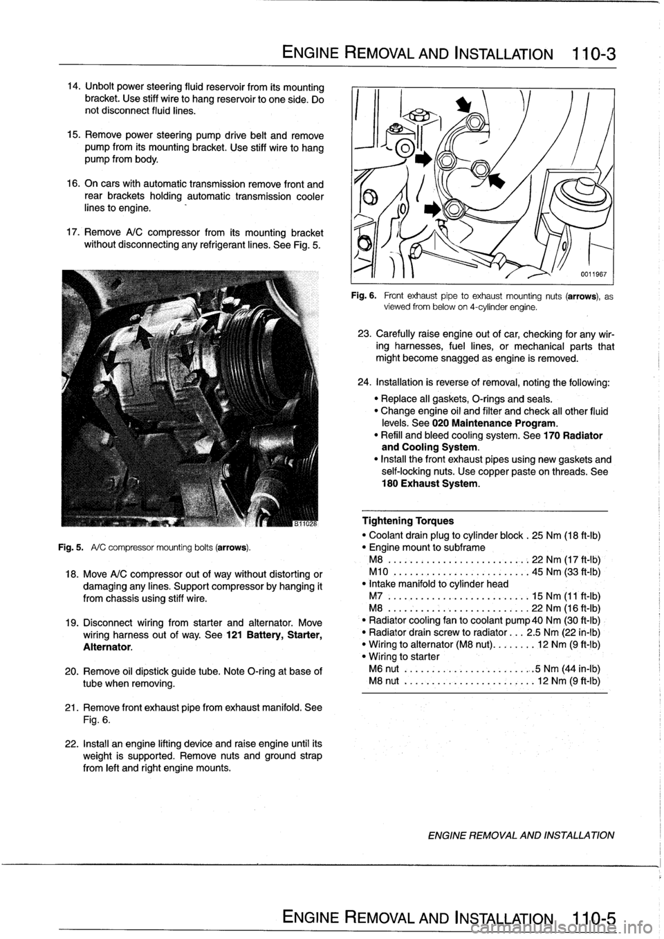
17
.
Remove
A/C
compressor
from
its
mounting
bracket
without
disconnecting
any
refrigerantlines
.
See
Fig
.
5
.
ENGINE
REMOVAL
AND
INSTALLATION
110-
3
21
.
Remove
front
exhaust
pipefrom
exhaust
manifold
.
See
Fig
.
6
.
22
.
Install
an
engine
lifting
device
and
raise
engine
until
its
weight
is
supported
.
Remove
nuts
and
ground
strap
from
left
and
right
engine
mounts
.
0011967
Fig
.
6
.
Front
exhaustpipe
to
exhaust
mounting
nuts
(arrows),
as
viewed
from
below
on
4-cylinder
engine
.
23
.
Carefully
raíse
engine
out
of
car,
checking
for
any
wir-
ing
harnesses,
fuel
lines,
or
mechanical
parts
that
might
become
snagged
as
engine
is
removed
.
24
.
Installation
is
reverse
of
removal,
noting
the
following
:
"
Replace
all
gaskets,
O-rings
and
seals
.
"
Change
engine
oil
and
filter
and
check
al¡
other
fluid
levels
.
See020
Maintenance
Program
.
"
Refill
and
bleed
cooling
system
.
See
170
Radiator
and
Cooling
System
.
"
Insta¡¡
the
front
exhaust
pipes
using
new
gaskets
and
self-locking
nuts
.
Use
copper
pasteon
threads
.
See
180
Exhaust
System
.
Tightening
Torques
"
Coolant
drain
plug
to
cylinder
block
.
25
Nm
(18
ft-Ib)
Fig
.
5
.
A/
C
compressor
mounting
bolts
(arrows)
.
"
Engine
mount
to
subframe
M8
......:...
..
..
..
......,:..
22
Nm
(17
ft
-
1b)
,
18
.
Move
A/C
compressor
out
of
way
without
distorting
or
M10
.
...
.
..
...
.
.
...........
45
Nm
(33
ft'-Ib)
damaging
any
lines
.
Support
compressor
by
hanging
it
"
Intake
manifold
to
cylinder
head
from
chassis
using
stiff
wire
.
M7
.....
.
..
...
..
..
...........
15
Nm
(11
ft-Ib)
M8
...
.
.
.
..
..
...
..
...........
22
Nm
(16
ft-Ib)
19
.
Disconnect
wiring
from
starter
and
alternator
.
Move
`
"
Radiator
cooling
fan
to
coolant
pump40
Nm
(30
ft-Ib)
wiring
harness
out
of
way
.
See
121
Battery,
Starter,
"
Radiator
drain
screw
to
radiator
...
2
.5
Nm
(22
in-lb)
Alternator
.
"
Wiring
to
alternator
(M8
nut)
........
12
Nm
(9
ft-1b)
"
Wiring
to
starter
20
.
Remove
oil
dipstick
guide
tube
.
Note
O-ring
at
base
of
M6
nut
..
.
..
..
...
..
...........
.
:5
Nm
(44
in-lb)
tube
when
removing
.
M8
nut
..
.
..
..
...
..
............
12
Nm
(9
ft-Ib)
ENGINE
REMOVAL
AND
INSTALLATION
Page 65 of 759
22
.
Move
A/C
compressor
out
of
the
way
without
distorting
26
.
Carefully
raise
engine
out
ofcar,
checking
for
any
wir-
or
damaging
any
lines
.
Support
compressor
by
hanging
ing,fuel
lines,
or
mechanical
parts
that
might
become
it
from
chassis
using
stiff
wire
.
snagged
as
engine
is
removed
.
23
.
Disconnect
wiring
from
starter
and
alternator
.
Move
27
.
Installation
is
reverse
of
removal,
noting
the
following
:
wiring
harness
out
of
the
way
.
See
121
Battery,
Start-
Replace
al¡
gaskets,
O-rings
and
seals
.
er,
Alternator
.
"
Change
engine
oil
and
filter
and
check
all
other
fluid
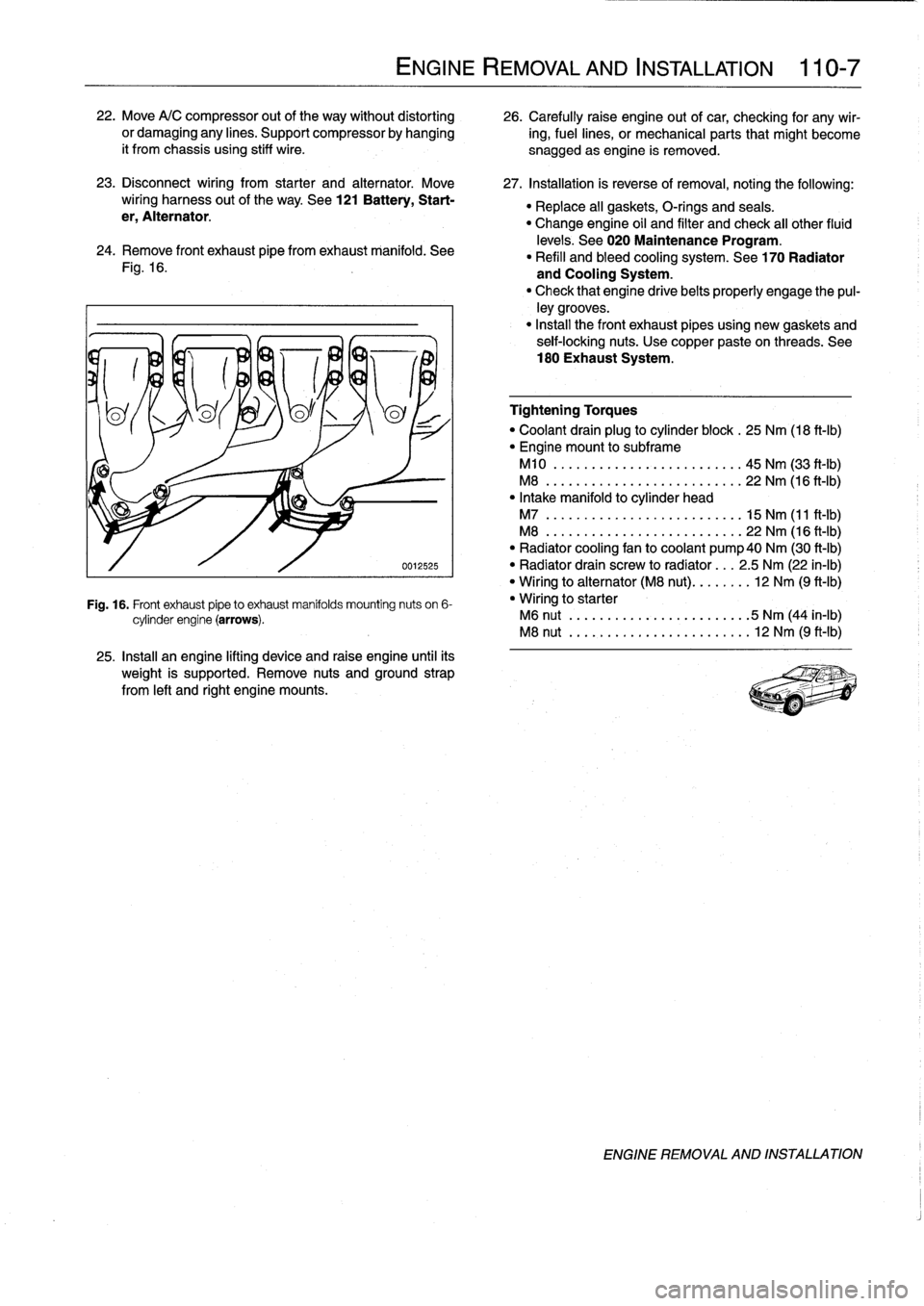
24
.
Remove
Fontexhaust
pipe
fromexhaust
manifold
.
See
levels
.
See
020
Maintenance
Program
.
"
Refill
and
bleed
cooling
system
.
See
170
Radiator
Fig
.
16
.
and
Cooling
System
.
"
Check
that
engine
drivebelts
properly
engage
the
pul-
ley
grooves
.
"
Install
the
Font
exhaust
pipesusing
new
gaskets
and
seif-locking
nuts
.
Use
copper
paste
on
threads
.
See
180
Exhaust
System
.
0012525
Fig
.
16
.
Front
exhaust
pipeto
exhaust
manifolds
mounting
nuts
on
6-
cylinder
engine
(arrows)
.
25
.
Install
an
engine
lifting
device
and
raise
engine
until
its
weight
is
supported
.
Remove
nuts
and
ground
strap
from
left
and
right
engine
mounts
.
ENGINE
REMOVAL
AND
INSTALLATION
110-
7
Tightening
Torques
"
Coolant
drain
plug
to
cylinder
block
.
25
Nm
(18
ft-Ib)
"
Engine
mount
to
subframe
M10
..
.
.
.
...
..............
..
.
45
Nm
(33
ft-Ib)
M8
..
..
.
..
................
...
22
Nm
(16
ft-Ib)
"
Intake
manifold
to
cylinder
head
M7
..
..
..
...
................
.
15
Nm
(11
ft-Ib)
M8
...
.
..
...
................
.
22
Nm
(16
ft-Ib)
"
Radiator
cooling
fan
to
coolant
pump40
Nm
(30
ft-Ib)
"
Radiator
drain
screw
to
radíator
...
2
.5
Nm
(22
in-lb)
"
Wiring
to
alternator
(M8
nut)
........
12
Nm
(9
ft-Ib)
"
Wiring
to
starter
M6
nut
.
..
...
..................
5
Nm
(44
in-lb)
M8
nut
.....
..
.
.
.
.
.............
12
Nm
(9
ft-Ib)
ENGINE
REMOVAL
AND
INSTALLATION
Page 73 of 759
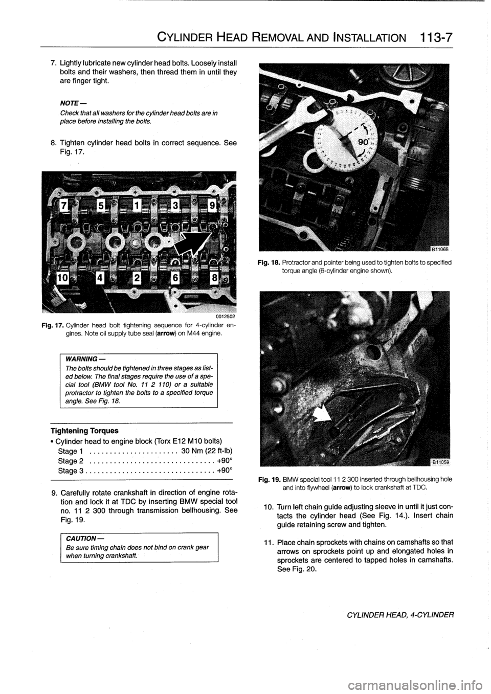
7
.
Lightly
lubricate
new
cylinder
head
bolts
.
Loosely
instan
bolts
and
their
washers,
then
thread
them
in
until
they
are
finger
tight
.
NOTE-
Check
that
all
washers
for
the
cylinder
head
bolts
are
in
place
before
installing
the
bolts
.
8
.
Tighten
cylinder
head
bolts
in
correct
sequence
.
See
Fig
.
17
.
UU125U2
Fig
.
17
.
Cylinder
head
bolt
tightening
sequence
for
4-cylinder
en-
gines
.
Note
oil
supply
tube
seal
(arrow)
on
M44
engine
.
WARNING
-
The
bolts
should
be
tightennd
in
three
stages
as
líst-
ed
below
.
The
final
stages
require
the
use
of
a
spe-
cial
tool
(BMW
tool
No
.
11
2
110)
ora
suitable
protractor
to
tighten
the
bolts
to
a
specified
torqueangle
.
See
Fig
.
18
.
Tightening
Torques
"
Cylinder
head
to
engine
block
(Torx
El2
M10
bolts)
Stage
1
.
.
.....
.
.
.............
30
Nm
(22
ft-Ib)
Stage
2
.
...
...
.
.
...................
..
.
+90°
Stage
3
.....
...
.
..
...................
..
+90°
9
.
Carefully
rotate
crankshaft
in
direction
of
engine
rota-
tion
and
lock
it
at
TDC
by
inserting
BMW
special
tool
no
.
11
2
300
through
transmission
bellhousing
.
See
Fig
.
19
.
CYLINDER
HEAD
REMOVAL
AND
INSTALLATION
113-
7
Fig
.
18
.
Protractor
and
pointer
being
used
to
tighten
bolts
to
specified
torqueangle
(6-cylinder
engine
shown)
.
Fig
.
19
.
BMW
special
tool
11
2
300
inserted
through
bellhousing
hole
and
finto
flywheel
(arrow)
to
lockcrankshaft
at
TDC
.
10
.
Turn
left
chainguide
adjusting
sleeve
in
until
it
just
con-
tacts
the
cylinder
head
(See
Fig
.
14
.)
.
Insert
chain
guide
retaining
screw
and
tighten
.
CAUTION-
11
.
Placechain
sprockets
with
chains
oncamshaftsso
that
Be
sure
timing
chain
does
not
bind
oncrank
gear
when
turning
crankshaft
.
arrowson
sprockets
point
up
and
elongated
holes
in
sprocketsare
centered
to
tapped
holes
in
camshafts
.
See
Fig
.
20
.
CYLINDER
HEAD,
4-CYLINDER
Page 74 of 759
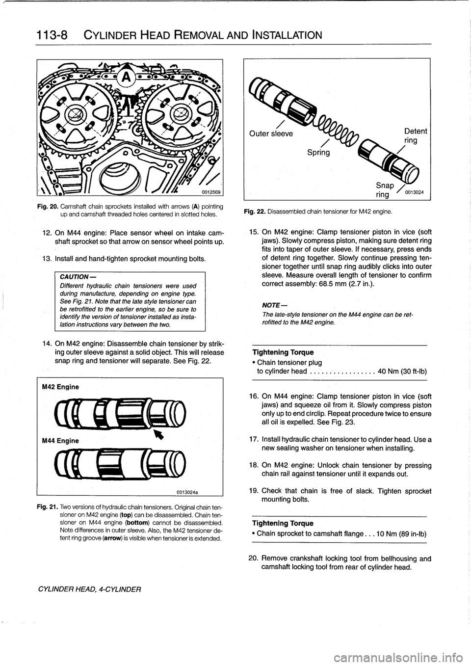
113-8
CYLINDER
HEAD
REMOVAL
AND
INSTALLATION
IW?
-
L
'/~f
W
~
4r
"
-
"
;,s
1
12
.
On
M44
engine
:
Place
sensor
wheel
on
intake
cam-
shaft
sprocket
so
that
arrowon
sensor
wheel
points
up
.
13
.
Instan
and
hand-tighten
sprocket
mounting
bolts
.
CAUTION-
Different
hydraulic
chaintensioners
were
used
during
manufacture,
depending
onengine
type
.
See
Fig
.
21
.
Note
that
the
late
style
tensioner
can
be
retrofitted
to
the
earlier
engine,
so
be
sure
to
identify
the
version
of
tensioner
installed
as
insta-lation
instructions
vary
between
the
two
.
14
.
On
M42
engine
:
Disassemble
chain
tensioner
by
strik-
ing
outer
sleeve
against
a
solid
object
.
This
will
release
snap
ring
and
tensioner
will
separate
.
See
Fig
.
22
.
M42
Engine
up
and
camshaft
threaded
holes
centered
in
siotted
holes
.
CYLINDER
HEAD,
4-CYLINDER
0013024a
Outer
sl
eve
Detent
ring
Spri
g
Fig
.
22
.
Disassembled
chain
tensioner
for
M42
engine
.
15
.
On
M42
engine
:
Clamp
tensioner
piston
in
vice
(soft
jaws)
.
Slowly
compress
piston,
making
sure
detent
ring
fits
into
taper
of
outer
sleeve
.
If
necessary,
press
ends
of
detent
ring
together
.
Slowly
continuepressing
ten-
sioner
together
until
snap
ring
audibly
clicksinto
outer
sleeve
.
Measure
overall
lengthof
tensioner
to
confirm
correct
assembly
:
68
.5
mm
(2.7
in
.)
.
NOTE-
i
Snap
ring
/0
.13024
The
late-style
tensioner
on
the
M44
engíne
canbe
ret-
rofitted
to
the
M42
engine
.
Tightening
Torque
"Chain
tensioner
plug
to
cylinder
head
.....
.-~
..........
40
Nm
(30
ft-Ib)
16
.
On
M44
engíne
:
Clamp
tensioner
píston
in
vice
(soft
jaws)
and
squeeze
oil
from
it
.
Slowly
compress
piston
only
up
to
end
circlip
.
Repeat
procedure
twice
to
ensure
all
oil
is
expelled
.
See
Fig
.
23
.
17
.
Instan
hydraulic
chain
tensioner
to
cylinder
head
.
Use
a
new
sealing
washer
on
tensioner
when
installing
.
18
.
On
M42
engine
:
Unlock
chain
tensioner
by
pressing
chain
rail
against
tensioner
until
it
expands
out
.
19
.
Check
that
chain
is
free
of
slack
.
Tighten
sprocket
mounting
bolts
.
Fig
.
21
.
Two
versions
of
hydraulic
chain
tensioners
.
Original
chainten-
sioner
on
M42
engine
(top)
can
be
disassembled
.
Chain
ten
sioner
on
M44
engine
(bottom)
cannotbe
disassembled
.
Tightening
Torque
Note
differences
in
outer
sleeve
.
Also,
the
M42
tensioner
de-
"
Chain
sprocket
to
camshaft
flange
.
..
10
Nm
(89
in-lb)
tent
ring
groove
(arrow)
is
visible
when
tensioner
is
extended
.
20
.
Remove
crankshaft
locking
tool
from
bellhousing
and
camshaft
locking
tool
from
rear
of
cylinder
head
.