fault BMW M3 1995 E36 Owner's Manual
[x] Cancel search | Manufacturer: BMW, Model Year: 1995, Model line: M3, Model: BMW M3 1995 E36Pages: 759
Page 92 of 759
116-
8
CYLINDER
HEAD
AND
VALVETRAIN
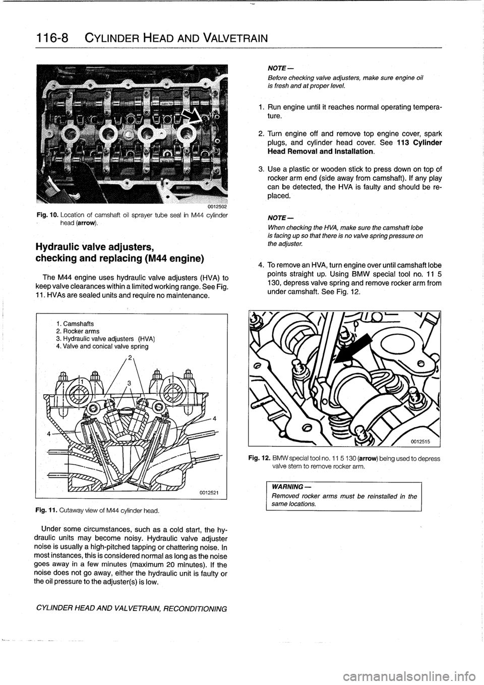
0012502
Fig
.
10
.
Location
of
camshaft
oil
sprayer
tube
sea¡
in
M44
cylinder
head
(arrow)
.
Hydraulic
valve
adjusters,
checking
and
replacing
(M44
engine)
The
M44
engine
uses
hydraulic
valveadjusters
(HVA)
to
keep
valve
clearances
within
a
limited
working
range
.
See
Fig
.
11
.
HVAs
are
sealed
units
and
require
no
maintenance
.
1
.
Camshafts
2
.
Rocker
arms
3
.
Hydraulic
valve
adjusters
(HVA)
4
.
Valve
and
conical
valve
spring
Fig
.
11
.
Cutaway
view
of
M44
cylinder
head
.
Under
some
circumstances,
such
as
a
cold
start,
thehy-
draulic
units
may
become
noisy
.
Hydraulic
valve
adjusternoise
is
usually
ahigh-pitched
tapping
or
chattering
noise
.
In
most
instances,
this
is
consídered
normal
aslong
as
the
noise
goes
away
in
a
few
minutes
(maximum20
minutes)
.
If
thenoise
does
not
go
away,
either
the
hydraulic
unit
is
faulty
orthe
oil
pressure
tothe
adjuster(s)
is
low
.
CYLINDER
HEAD
AND
VALVETRAIN,
RECONDITIONING
NOTE-
8efore
checking
valveadjusters,
make
sure
engine
oil
is
fresh
and
at
proper
level
.
1
.
Run
engine
until
it
reaches
normal
operating
tempera-
ture
.
2
.
Turn
engine
off
and
remove
top
engine
cover,
spark
plugs,
and
cylinder
head
cover
.
See
113
Cylinder
Head
Removal
and
Installation
.
3
.
Use
a
plastic
or
wooden
stick
to
press
down
on
top
of
rocker
armend
(side
away
from
camshaft)
.
If
any
play
can
be
detected,the
HVA
is
faulty
and
should
be
re-
placed
.
NOTE-
When
checking
the
HVA,
make
sure
the
camshaft
lobe
is
facing
upso
that
there
is
no
valve
spring
pressure
on
the
adjuster
.
4
.
To
remove
an
HVA,
turn
engine
over
until
camshaft
lobe
points
straight
up
.
Using
BMW
special
tool
no
.
11
5
130,
depress
valvespring
and
remove
rocker
arm
from
under
camshaft
.
See
Fig
.
12
.
Fig
.
12
.
BMW
special
tool
no
.
115
130
(arrow)
being
used
to
depress
valve
stem
to
remove
rocker
arm
.
WARNING
-
Removed
rocker
armsmustbe
reinstalled
in
the
same
locations
.
Page 93 of 759
5
.
Pull
hydraulic
valve
adjuster
straight
out
of
cylinder
head
.
See
Fig
.
13
.
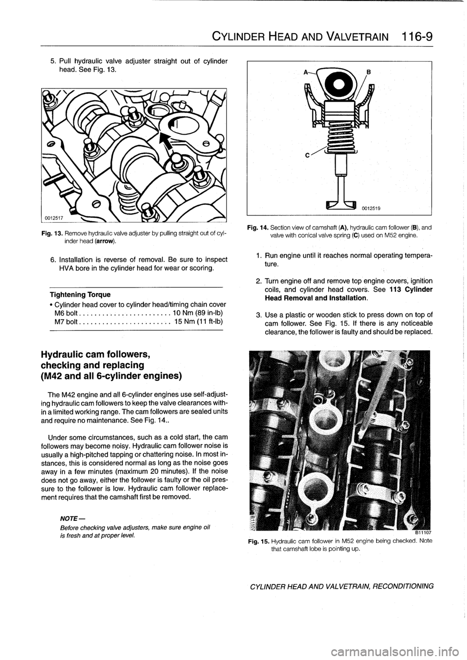
Fig
.
13
.
Remove
hydraulic
valve
adjuster
by
pulling
straight
out
ofcyl-
inder
head
(arrow)
.
6
.
Installation
is
reverse
of
removal
.
Be
sure
to
inspect
HVA
bore
in
the
cylinder
head
for
wear
or
scoring
.
Tightening
Torque
"
Cylinder
head
cover
to
cylinder
head/timing
chain
cover
M6
bolt
.........
..
..
...
........
10
Nm
(89
in-lb)
M7
bolt
.......
.
.
..
...
.
...
.
.....
15
Nm
(11
ft-Ib)
Hydraulic
cam
followers,
checking
and
replacing
(M42
and
al¡
6-cylinder
engines)
The
M42
engine
and
al¡
6-cylinder
engines
use
self-adjust-
ing
hydraulic
cam
followers
to
keep
the
valveclearances
with-
ina
limited
working
range
.
The
cam
followers
are
sealed
units
and
require
no
maintenance
.
See
Fig
.
14
.
.
Under
some
circumstances,
suchasa
cold
start,
the
cam
followers
may
become
noisy
.
Hydraulic
cam
follower
noise
is
usually
a
high-pitched
tapping
or
chattering
noise
.
In
most
in-
stances,
this
is
considered
normalas
long
as
the
noise
goes
away
in
a
fewminutes
(maximum
20
minutes)
.
lf
the
noise
does
not
go
away,
either
the
follower
is
faulty
or
the
oil
pres-
sure
to
the
follower
is
low
.
Hydraulic
cam
follower
replace-
ment
requires
that
the
camshaft
first
be
removed
.
NOTE-
Before
checking
valve
adjusters,
make
sure
engine
oil
ís
fresh
and
at
proper
level
.
CYLINDER
HEAD
AND
VALVETRAIN
116-
9
Fig
.
14
.
Section
view
of
camshaft
(A),
hydraulic
cam
follower
(B),
and
valvewith
conical
valvespring
(C)
usedon
M52
engine
.
1.
Run
engine
until
it
reachesnormal
operating
tempera-
ture
.
2
.
Turn
engine
off
and
remove
top
engine
covers,
ignition
coils,
and
cylinder
head
covers
.
See
113
Cylinder
Head
Removal
and
Installation
.
3
.
Use
a
plastic
or
wooden
stickto
press
down
on
top
of
cam
follower
.
See
Fig
.
15
.
If
there
is
any
noticeable
clearance,
the
follower
is
faulty
and
should
be
replaced
.
811107
Fig
.
15
.
Hydraulic
cam
follower
in
M52
enginebeing
checked
.
Note
that
camshaft
lobe
is
pointing
up
.
CYLINDER
HEAD
AND
VALVETRAIN,
RECONDITIONING
Page 94 of 759
116-
1
0
CYLINDER
HEADAND
VALVETRAIN
NOTE-
When
checking
a
cam
follower,
make
sure
the
corre-
sponding
camshaft
lobe
ís
facing
up
so
that
there
is
no
valve
spring
pressure
on
the
follower
.
4
.
To
replace
a
cam
follower,
remove
appropriate
cam-
shaft
.
Refer
to
camshaft
removal
procedures
given
ear-
lier
.
5
.
Once
camshaft
is
out
of
way,
withdraw
faulty
cam
fol-
lower
and
replace
with
new
one
.
Inspect
cam
follower
bores
for
wear
and
scoring
.
6
.
Camshaft,
timing
chain
and
cylinder
head
cover
reas-
sembly
is
reverse
of
disassembly
.
Tightening
Torques
"
Camshaft
bearing
caps
to
cylinder
head
M7
....
.
..
.
......
.
.....
...
.
..
.
15
Nm
(11
ft-Ib)
"
Cylinder
head
cover
to
cylinder
headltiming
chain
cover
M6
....
.
..
.
.
.
..........
...
.
.
..
10
Nm
(89
in-lb)
"
Timing
chain
hydraulic
tensioner
to
cylinder
head-see
117
Camshaft
Timing
Chain
"
Timing
chain
sprocket
to
camshaft
flange
(M6)-see
117
Camshaft
Timing
Chain
CYLINDER
HEAD
AND
VALVETRAIN,
RECONDITIONING
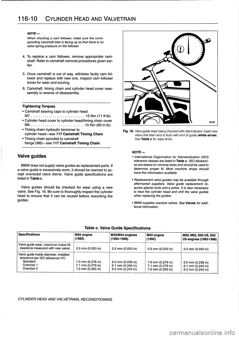
Table
c
.
Valve
Guide
Specifications
Fig
.
16
.
Valveguide
wear
being
checked
with
dial
indicator
.
Insert
new
valve
until
stem
end
is
flush
with
end
of
guide(white
arrow)
.
See
Table
c
for
wear
limits
.
NOTE-
Valve
guides
"
Intemational
Organization
for
Standardization
(ASO)
tolerance
classes
are
Gsted
in
Table
c
.
ISO
allowanc
BMW
does
notsupply
valve
guides
as
replacement
parts
.
If
esare
based
on
nominal
sizes
and
should
beused
to
a
valve
guide
is
excessively
worn,
it
should
be
reamed
to
ac-
determine
proper
fit
.
Most
machine
shops
should
cept
oversized
valve
stems
.
Valve
guide
specifications
are
have
thís
informationavailable
listed
in
Table
c
.
"
Replacement
valve
guides
may
be
available
through
aftermarket
suppliers
.
Valve
guide
replacement
re-
Valve
guides
should
be
checked
for
wear
using
a
new
quires
specíal
tools
and
a
press
.
It
is
also
necessary
valve
.
See
Fig
.
16
.
Be
sure
to
thoroughly
inspect
the
cylinder
to
heat
the
cylinder
head
and
chile
the
valve
guides
head
to
ensure
that
it
can
be
reused
before
reworking
the
when
replacing
the
guides
.
guides
.
"
BMW
suppllesoversize
valves
.
Sea
Valves
for
addi-
tional
information
.
Specifications
M42
engine
M421M44
engines
M50
engine
M50,M52,
S50
US,
S52
~
(1992)
~
(1993-1998)
~
(1992)
~
US
engines
(1993-1998)
Valve
guide
wear,
maximum
(valve
tílt
clearance
measured
with
new
valve)
0
.5
mm
(0
.020
in)
0
.5
mm
(0
.020
in)
0
.5
mm
(0
.020
in)
0
.5
mm
(0
.020
in)
Valveguide
inside
diameter,
installed
(tolerance
per
ISO
allowance
H7)
Standard
7
.0
mm
(0
.276
in)
6
.0
mm
(0
.236
in)
7
.0
mm
(0.276
in)
6
.0
mm
(0
.236
in)
Oversize
1
7
.1
mm
(0
.279
in)
6
.1
mm
(0
.240
in)
7
.1
mm
(0.279
in)
6
.1
mm
(0
.240
in)
Oversize
2
7
.2
mm
(0
.283
in)
6
.2
mm
(0
.244
in)
7
.2
mm
(0
.283
in)
6
.2
mm
(0
.244
in)
Page 97 of 759
GENERAL
......
.
.
.
.
.
.
.
.
.
...
.
.
.
.
.
.
.
.
.
.
117-1
Camshaft
timing
chains,
removing
(6-cylinder
engines)
....
.
....
..
....
..
...
.117-7
CAMSHAFT
TIMING
CHAIN,
Camshaft
timing
chains,
installing
4-CYLINDER
....
.
.
.
.
.
.
.
.
.
.
.
.......
.
...
117-2
6-clinderen
nes
117-11
Camshaft
timingchain,
removing
(
y
gi
(4-cylinder
engines)
...
..
....
..
...
...
....
117-2
VANOS
(VARIABLE
VALVE
TIMING)
.
..
117-14
Camshaft
timingchain,
installing
VANOS
system
operation,
testing
.....
.
....
117-14
(4-cylinder
engines)
...
..
...
....
..
.
.....
117-4
VANOS
control
unit,
removing
.
..
..........
117-16
CAMSHAFT
TIMINGCHAINS,
VANOS
control
unit,
installing
..
..
..........
117-17
6-CYLINDER
.
.........................
117-6
GENERAL
117
Camshaft
Timing
Chain
This
repair
group
covers
timing
chain
repair
information
for
the
4-
and
6-cylinder
engines
.
4-cylinder
enginesuse
one
double-row
chain
to
drive
the
dual
overhead
camshafts
.
See
Fig
.
1
.
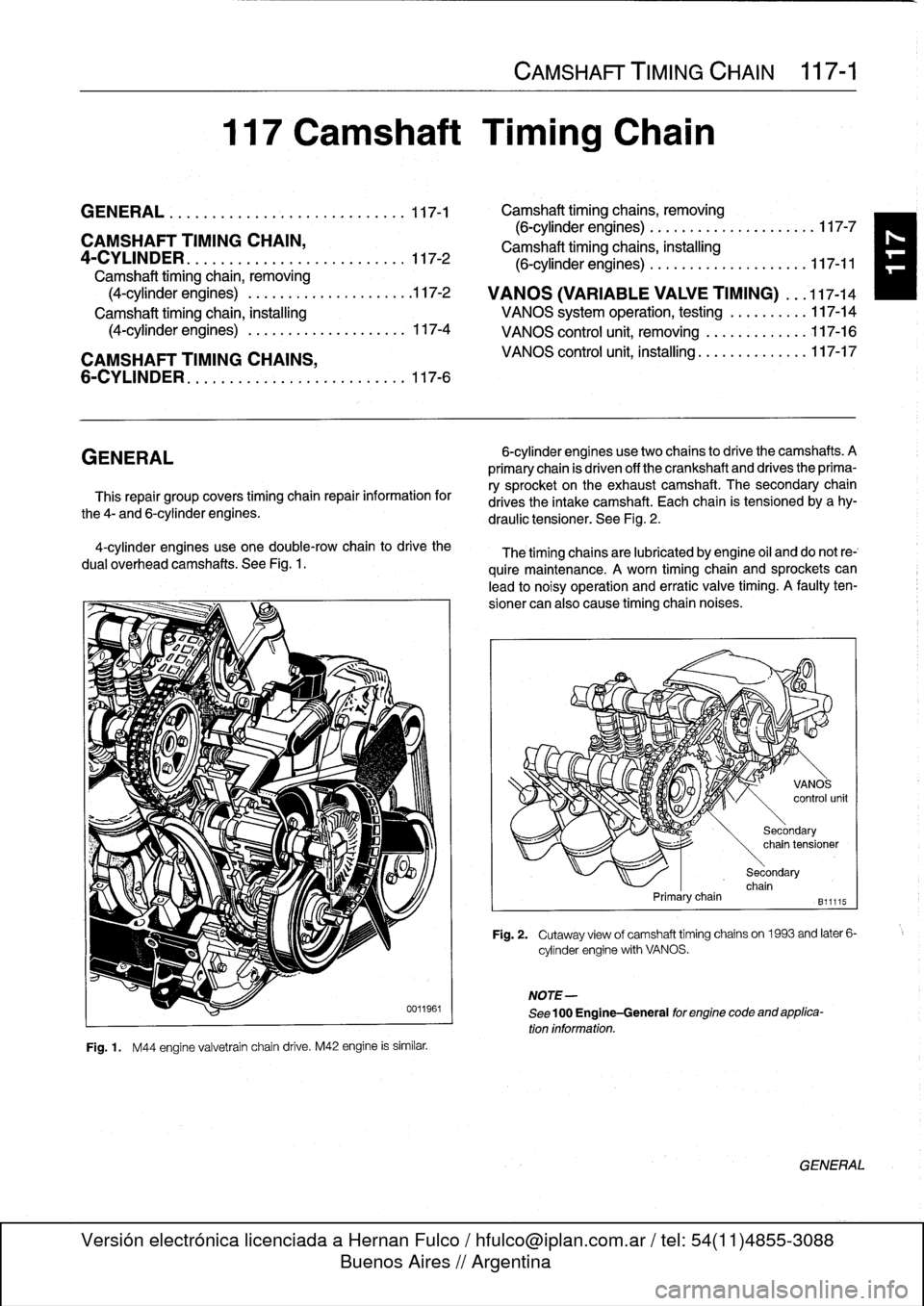
Fig
.
1
.
M44
engine
valvetrain
chain
drive
.
M42
engine
is
similar
.
CAMSHAFT
TIMING
CHAIN
117-1
6-cylinder
enginesusetwo
chains
to
drive
the
camshafts
.
A
primary
chain
is
driven
off
the
crankshaft
and
drives
the
prima-
ry
sprocket
on
the
exhaustcamshaft
.
The
secondary
chain
drives
the
intake
camshaft
.
Each
chain
is
tensioned
by
a
hy-
draulic
tensioner
.
See
Fig
.
2
.
The
timing
chainsare
lubricated
by
engine
oil
and
do
not
re-`
quire
maintenance
.
A
worn
timing
chain
and
sprockets
can
lead
to
noisy
operation
and
erratic
valve
timing
.
A
faulty
ten-
sioner
can
also
cause
timing
chaín
noises
.
Primarychain
NOTE-
See
100
Engine-General
for
engine
code
and
applica-
tion
information
.
Secondary
chain
tensioner
Secondary
chain
B11115
Fig
.
2
.
Cutaway
view
of
camshaft
timing
chains
on1963
and
later
6-
cylinder
engine
with
VANOS
.
GENERAL
Page 103 of 759
Camshaft
timing
chains,
removing
(6-cylinder
engines)
1
.
Disconnect
negative
(-)
cable
from
battery
.
CA
UTION-
Disconnecting
the
battery
may
erase
fault
codes)
stored
in
control
module
memory
.
Check
for
fault
codes
using
special
BMW
diagnostic
equipment
.
2
.
Drain
engine
coolant
.
Drain
engine
block
by
removing
block
drain
.
Remove
radiator
cooling
fan
shroud
and
cooling
fan
.
See170
Radiator
and
Cooling
System
.
.
WARNING
-
Allow
the
engine
to
cool
before
openingor
draining
the
system
.
CAUTION-
Radiator
fan
has
left
hand
threads
.
NOTE-
The
block
drain
plug
is
located
on
the
exhaust
side
of
the
engine,
below
cylinder
no
.
4
.
3
.
Drain
engine
oíl
andremove
oil
pan
.
See
119
Lubrica-
tion
System
.
4
.
Remove
alternator
cooling
duct
.
5
.
Remove
two
large
coolant
hoses
from
thermostat
housing
.
Remove
engine
lifting
bracket
and
thermostat
housing
from
front
of
cylinder
head
.
6
.
Loosen
bolts
for
coolant
pump
pulley
.
Then
remove
drive
belts
for
alternator
andA/C
compressor
.
See
020
Maintenance
Program
.
Remove
coolant
pump
pulley
.
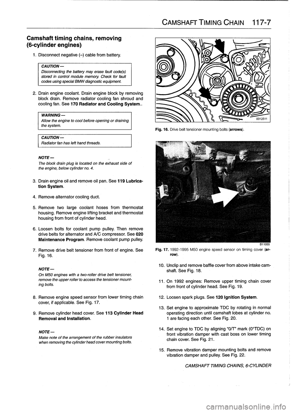
Fig
.
16
.
NOTE-
OnM50
engines
with
a
two-roller
drive
belt
tensioner,
remove
the
upper
rollerto
access
thetensioner
mount-
ing
bolts
.
NOTE-
Make
note
of
the
arrangement
of
the
rubber
insulators
when
removing
the
cylinder
head
cover
mounting
bolts
.
CAMSHAFT
TIMING
CHAIN
117-
7
Fig
.
16
.
Drive
belt
tensioner
mounting
bolts
(arrows)
.
B11055
7
.
Remove
drive
belt
tensioner
from
front
of
engine
.
See
Fig
.
17
.
1992-1995
M50
engine
speed
sensor
on
timing
cover
(ar-
row)
.
10
.
Unclip
andremove
baffle
cover
from
above
intake
cam-
shaft
.
See
Fig
.
18
.
11
.
On
1992
engines
:
Remove
upper
timing
chain
cover
from
front
of
cylinder
head
.
See
Fig
.
19
.
8
.
Remove
engine
speed
sensor
from
lower
timing
chain
12
.
Loosen
spark
plugs
.
See
120
Ignition
System
.
cover,
if
applicable
.
See
Fig
.
17
.
13
.
Set
engine
to
approximate
TDC
by
rotating
in
normal
9
.
Remove
cylinder
head
cover
.
See
113
Cylinder
Head
operating
direction
until
camshaft
lobes
at
cylinder
no
.
Removal
and
Installatíon
.
1
are
facing
each
other
.
See
Fig
.
20
.
14
.
Set
engine
to
TDC
by
aligning
"0/T'
mark
(0°TDC)on
front
vibration
damper
with
cast
bosson
lower
timing
chain
cover
.
See
Fig
.
21
.
15
.
Remove
vibration
damper
mounting
bolts
and
remove
vibration
damper
and
pulley
.
See
Fig
.
22
.
CAMSHAFT
TIMING
CHAINS,
6-CYLINDER
Page 109 of 759
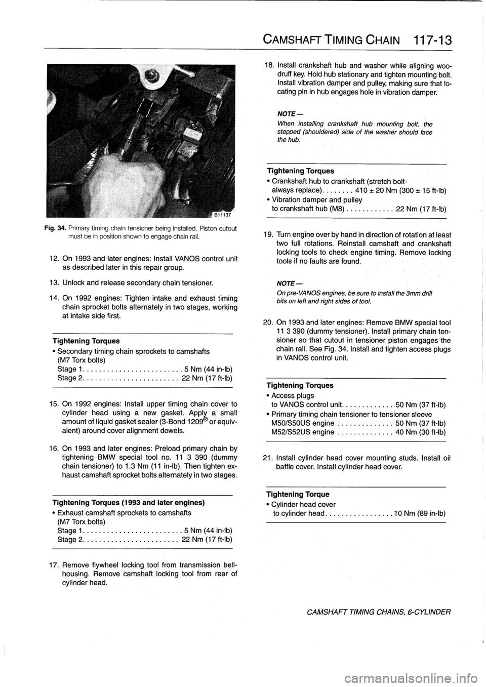
Fig
.
34
.
Primary
timíng
chain
tensioner
being
instafed
.
Pistoncutout
mustbe
in
position
shown
to
engage
chain
rail
.
12
.
On
1993
and
later
engines
:
Install
VANOS
control
unit
as
described
later
in
this
repair
group
.
13
.
Unlock
and
release
secondary
chaintensioner
.
NOTE-
On
pre-VANOS
engines,
be
sure
toinstall
the
3mm
drill
bits
on
left
and
right
sides
of
tool
.
14
.
On
1992
engines
:
Tighten
intake
and
exhaust
timing
chain
sprocket
bolts
alternately
in
two
stages,
working
at
intake
side
first
.
Tightening
Torques
"
Secondary
timing
chaira
sprockets
to
camshafts
(M7
Torx
bolts)
Stage
1
....
.
.
.
...
...............
5
Nm
(44
in-lb)
Stage
2
..
.
.
.
.
.
.
................
22
Nm
(17
ft-Ib)
15
.
On
1992
engines
:
Install
upper
timing
chaincover
to
cylinder
head
using
a
new
gasket
.
Apply
a
small
amount
ofliquid
gasket
sealer
(3-Bond
1209
®
orequiv-
alent)
around
coveralignment
dowels
.
16
.
On
1993
and
later
engines
:
Preloadprimary
chain
by
tightening
BMW
special
tool
no
.
11
3
390
(dummy
21
.
Install
cylinder
head
cover
mounting
studs
.
Insta¡¡
oil
chain
tensioner)
to
1
.3
Nm
(11
in-lb)
.
Then
tighten
ex-
baffle
cover
.
Install
cylinder
head
cover
.
haust
camshaft
sprocket
bolts
alternately
in
twostages
.
Tightening
Torques
(1993
and
later
engines)
"
Exhaust
camshaft
sprockets
to
camshafts
(M7
Torx
bolts)
Stage
1
..
...
..
..
................
5
Nm
(44
in-lb)
Stage
2
.....
.
.
...
..............
22
Nm
(17
ft-Ib)
17
.
Remove
flywheel
locking
tool
from
transmission
bell-
housing
.
Remove
camshaft
locking
tool
from
rear
of
cylinder
head
.
CAMSHAFT'TIMING
CHAIN
117-
1
3
18
.
Insta¡¡
crankshaft
hubandwasher
while
aligning
woo-
druff
key
.
Hold
hub
stationary
and
tighten
mounting
bolt
.
Install
vibration
damper
and
pulley,
making
sure
that
lo-
cating
pin
in
hub
engages
hole
in
vibration
damper
.
NOTE-
When
installing
crankshaft
hub
mounting
bolt,
the
stepped
(shouldered)
sideof
the
washer
should
fase
the
hub
.
Tightening
Torques
Crankshaft
hub
to
crankshaft
(stretch
bolt-
always
replace)
........
410
±
20
Nm
(300
±
15
ft-1b)
"
Vibration
damper
and
pulley
to
crankshaft
hub
(M8)
...
..
.
..
....
22
Nm
(17
ft-Ib)
19
.
Turn
engine
over
by
hand
in
direction
of
rotation
atleast
two
full
rotations
.
Reinstall
camshaft
and
crankshaft
locking
tools
to
check
engine
timing
.
Remove
locking
tools
if
no
faults
are
found
.
20
.
On
1993
and
later
engines
:
Remove
BMW
special
tool11
3
390
(dummy
tensioner)
.
Install
primary
chain
ten-sioner
so
that
cutout
in
tensioner
piston
engages
the
chain
rail
.
See
Fig
.
34
.
Install
and
tighten
access
plugs
in
VANOS
control
unit
.
Tightening
Torques
"
Access
plugs
to
VANOS
control
unit
..........
.
..
50
Nm
(37
ft-Ib)
"
Primary
timing
chain
tensioner
to
tensioner
sleeve
M50/S50US
engine
.......
.
..
..
.
.
50
Nm
(37
ft-Ib)
M52/S52US
engine
..........
..
.
.
40
Nm
(30
ft-Ib)
Tightening
Torque
"
Cylinder
head
cover
to
cylinder
head
............
...
.
.10
Nm
(89
in-lb)
CAMSHAFT
TIMINGCHAINS,
6-CYLINDER
Page 111 of 759
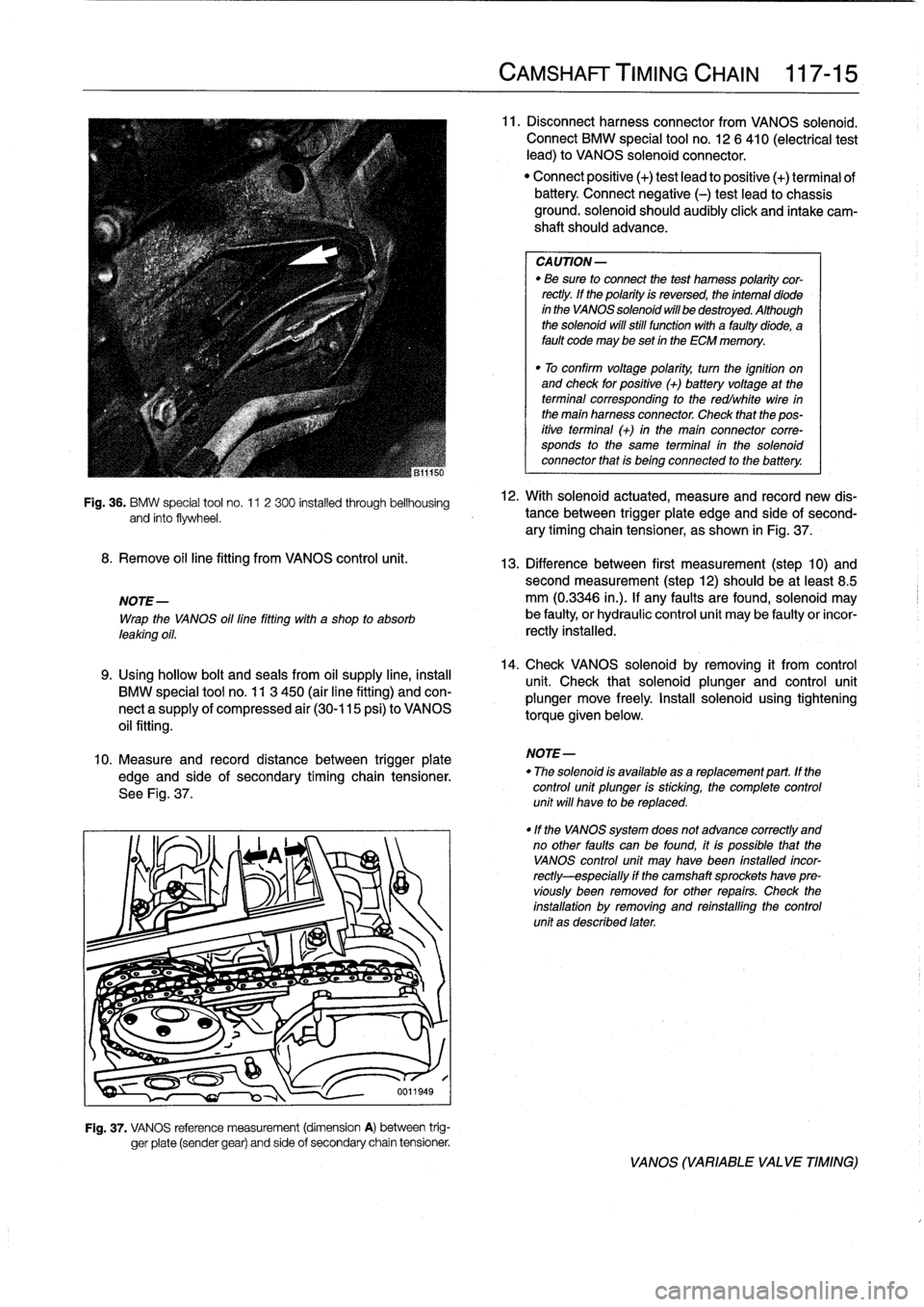
Fig
.
36
.
BMW
special
tool
no
.
11
2
300
installed
through
bellhousing
and
finto
flywheel
.
8
.
Remove
oil
line
fitting
from
VANOS
control
unit
.
NOTE-
Wrap
the
VANOS
oil
line
fitting
with
a
shop
to
absorb
leaking
oil
.
9
.
Using
hollow
bolt
and
seals
from
oil
supply
line,
instan
BMW
special
tool
no
.
11
3
450
(air
line
fitting)
and
con-
nect
a
supply
of
compressed
air
(30-115
psi)
to
VANOS
oil
fitting
.
10
.
Measure
and
record
distance
between
trigger
plate
edge
and
side
of
secondary
timing
chain
tensioner
.
See
Fig
.
37
.
Fig
.
37
.
VANOS
reference
measurement
(dimension
A)
between
trig-
ger
píate
(sender
gear)
and
side
of
secondary
chain
tensioner
.
CAMSHAFT
TIMING
CHAIN
117-
1
5
11
.
Disconnectharness
connector
from
VANOS
solenoid
.
Connect
BMW
special
tool
no
.
12
6
410
(electrical
test
lead)
to
VANOS
solenoid
connector
.
"
Connect
positive
(+)
test
lead
to
positive
(+)
terminal
ofbattery
Connect
negative
(-)
test
leadto
chassis
ground
.
solenoid
should
audibly
click
and
intake
cam-
shaft
should
advance
.
CA
UTION-
"
Be
sure
to
connect
the
test
hamess
polaritycor-
rectly
.
lf
the
polarity
is
reversed,
the
intemal
diode
in
the
VANOS
solenoid
will
be
destroyed
.
Although
the
solenoid
will
still
functionwith
a
faultydiode,
a
fault
code
may
be
set
in
the
ECM
memory
.
"
To
confirm
voltage
polarity,
turn
the
ignition
on
and
check
for
positive
(+)
batteryvoltage
at
the
terminal
corresponding
to
the
redlwhite
wire
in
the
main
harness
connector
.
Check
that
the
pos-
itive
terminal
(+)
in
the
main
connector
corre-
sponds
to
the
same
terminal
in
the
solenoid
connector
that
is
being
connected
to
the
battery
.
12
.
With
solenoid
actuated,
measure
and
record
new
dis-
tance
between
trigger
plate
edge
and
side'of
second-
ary
timing
chain
tensioner,
as
shown
in
Fig
.
37
.
13
.
Difference
between
first
measurement
(step
10)
andsecond
measurement
(step12)
should
be
at
least
8
.5
mm
(0
.3346
in
.)
.
lf
any
faults
arefound,
solenoid
may
be
faulty,
or
hydraulic
control
unit
may
be
faulty
or
incor-
rectly
installed
.
14
.
Check
VANOS
solenoid
byremoving
it
from
control
unit
.
Check
that
solenoid
plunger
and
control
unit
plunger
move
freely
.
Install
solenoid
using
tighteníng
torque
given
below
.
NOTE-
"
The
solenoid
is
available
asareplacement
part
.
lf
the
control
unit
plunger
is
sticking,
the
complete
control
unit
will
have
to
be
replaced
.
"lf
the
VANOS
system
does
not
advance
correctly
and
no
other
faults
can
be
found,
itis
possible
that
the
VANOS
control
unit
may
Nave
been
fnstalled
incor-
rectly-especially
if
the
camshaft
sprockets
have
pre-
víously
been
removed
for
other
repairs
.
Check
the
installation
by
removing
and
reinstalling
the
control
unit
as
described
later
.
VANOS
(VARIABLE
VALVE
TIMING)
Page 116 of 759
119-2
LUBRICATION
SYSTEM
NOTE-
Component
Location
If
the
light
does
not
go
out,
thewiring
to
theswitch
is"
Oil
pressure
switch
most
likely
grounded
somewhere
between
the
switch
all
engines
.......
...
.
..
......
ora
oil
filter
housing
terminal
and
the
warning
light
.
Sea
Electrical
Wiring
Diagrams
atrearof
manual
for
electrical
schematics
.
CAUTION-
Some
oil
may
drain
out
as
the
oil
pressure
switch
is
removed
.
Use
a
rag
to
soak
up
any
spills
.
2
.
Install
pressure
gauge
in
place
of
switch
.
3
.
With
gauge
instalied,
start
engine
and
allow
to
reach
operating
temperature
.
Check
oil
pressureboth
cold
and
hot
.
NOTE-
For
the
most
accurate
test
results,
the
engine
oil
(and
filter)
shouldbe
newand
of
the
correct
grade
.
Oil
Pressure
"
¡dle
(mínimum)
..
.
.
..............
.
.
0
.5
bar
(7psi)
"
Regulated
pressure
(elevated
engine
speed)
4-cylinder
engines
..
......
4
.3
±
0
.2
bar
(63
t3
psi)
6-cylinder
engines
.
.
.............
.
4
.0
bar
(59
psi)
4
.
Remove
pressure
gauge
and
reinstall
pressure
switch
.
If
testing
shows
low
oil
pressure,
one
or
more
of
the
follow-
ing
conditions
may
be
indicated
:
OIL
PAN
"
Worn
or
faulty
oii
pump
.
"
Worn
or
faulty
engine
bearings
The
oil
pancan
be
removed
with
the
engine
instalied,
al-
Severe
engine
wear
.
though
specíal
enginesupport
equipment
will
be
needed
.
Al¡
of
these
conditionsindicate
the
need
for
major
repairs
.
Oil
pressure
warning
system,
testing
When
the
ignition
is
tumed
ora,
the
oil
pressure
warning
light
comes
ora
.
When
the
engine
ís
started
and
the
oil
pressure
ris-
es
slightly,
the
oil
pressure
switch
opens
and
thewarning
light
goes
out
.
Make
sure
the
oil
leve¡
is
correct
before
making
tests
.
1
.
Turra
ignition
switch
ora
.
"
Warning
light
ora
instrument
panel
must
light
up
.
2
.
Remove
connector
from
oil
pressure
switch
.
"
Warning
light
ora
instrument
panel
must
go
out
.
OIL
PAN
3
.
If
warning
light
does
not
light
when
ignition
is
ora,
re-
move
connector
from
oil
pressure
switch
anduse
a
jumper
wire
to
ground
connector
terminal
to
a
clean
metal
surface
.
NOTE
-
If
the
warning
light
comes
ora,
check
the
switch
as
de-
scríbed
in
the
nextstep
.
If
the
warning
light
does
not
come
ora,
thewiring
to
the
instrument
cluster
or
to
the
light
itself
isfaulty
.
4
.
To
test
switch,
connect
ara
ohmmeter
between
terminal
in
switch
body
and
ground
.
With
engine
off,
these
should
be
continuity
.
With
engine
running,
oil
pressure
should
opera
switch
and
there
should
beno
continuity
Replace
a
faulty
switch
.
WARNING
-
Keep
in
mind
that
low
oil
pressure
may
be
prevent-
ing
the
switch
from
tuming
the
light
out
.
If
the
light
remains
ora
while
the
engine
is
running,
check
the
oil
pressure
asdescribed
earlier
.
Do
not
drive
the
car
until
the
problem
is
corrected
.
Theengine
may
be
severely
damaged
.
Oil
pan,
removing
and
installing
(4-cylinder
engines)
1
.
Raise
car
arad
place
securely
ora
jackstands
.
2
.
Remove
splash
shíeld(s)
from
under
engine,
where
ap-
plicable
.
3
.
Drain
engine
oil
as
described
in
020
Maintenance
Pro-
gram
.
4
.
Disconnect
vacuum
hose
adapter
from
vacuum
brake
booster
at
rear
of
engine
compartment
.
5
.
Remove
oil
dipstick
guide
tube
mounting
nut
and
pull
guide
tube
from
oil
pan
.
See
Fig
.
2
.
Page 127 of 759
IGNITION
SYSTEM
DIAGNOSTICS
IGNITION
SYSTEM
SERVICE
Poor
driveability
may
have
a
variety
of
causes
.
The
fault
On
4-cylinder
engines,
an
ignition
coil
pack
is
mounted
to
may
lie
with
the
ignition
system,
the
fuel
system,
parts
of
the
the
passenger
side
strut
tower
in
the
engine
compartment
.
emission
control
system,
or
a
combination
of
the
three
.
Be-
The
coil
pack
integrates
4
individual
coils
.
cause
of
these
interrelated
functions
and
their
effects
oneach
other,
it
is
often
difficult
to
know
where
to
begin
looking
for
On
6-cylinder
engines,
an
ignition
coil
is
located
directly
problems
.
above
each
spark
plug
.
For
this
reason,
effective
troubleshooting
should
alwaysbe-
gin
with
an
interrogation
of
the
On-Board
Diagnostic
(OBD)
system
.
The
OBD
system
detects
certain
emissions-related
engine
management
malfunctions
.
When
faults
are
detected,
the
OBD
system
stores
a
Diagnostic
Trouble
Code
(DTC)
in
the
system
ECM
.
In
addition,
the
Check
Enginewarning
light
will
come
on
if
an
emissions-related
fault
is
detected
.
Two
generations
of
OBD
areusedon
the
cars
coveredby
this
manual
.
See
100
Engine-General
for
OBD
information
.
On-Board
Diagnostics
"
1992-1995
models
............
...
.
..
...
OBD
I
"
1996
and
later
models
.........
.......
..
OBD
II
NOTE-
"
On
carswith
OBD
ti,
specialized
OBD
11
scan
tool
equipment
mustbeused
to
access
DTCs,
either
using
the
BMW
special
tool
or
a
`generic"
OBD
11
scan
tool
.
"
The
OBD
11
fault
memory
(including
an
illuminated
Check
Engine
light)
can
only
be
reset
using
the
spe-
cial
scan
tool
.
Removing
the
connector
from
the
ECM
or
dísconnecting
the
battery
will
not
erase
the
fault
memory
.
Basic
Troubleshooting
Principies
An
engine
that
starts
and
runs
indicates
the
ignition
system
is
fundamentally
working-delivering
voltage
toat
least
some
of
the
sparkplugs
.
A
hard-starting
or
poor-running
engine,
however,
may
indicate
ignition
coil
problems,
cracked
or
dete-
riorated
spark
plug
wires
(4-cylinder
engines
only),
and
worn
or
fouled
spark
plugs
.
WARNING
-
Inefficient
combustion
(richair/fuel
mixture)
can
cause
the
catalytic
converter
to
overheat
and
plug
.
An
overheated
catalytic
converter
can
also
bea
tire
hazard
.
Checking
for
Spark
IGNITION
SYSTEM
120-
3
WARNING
-
If
a
spark
test
is
done
incorrectly,
damage
to
theen-
gine
control
module
(ECM)
or
the
ignitioncoil(s)
may
result
.
Checking
for
spark
is
difficult
onengines
with
distributorless
ignition
systems
.
Try
Rmovng
the
plugs
and
inspecting
for
differences
be-
tween
them
.
A
poor-firing
plug
may
be
wet
with
fuel
and/or
black
and
sooty,
butnot
always
.
If
a
coil
is
not
operating,
the
engine
management
system
will
electrically
disable
the
fuel
injectorto
that
cylinder
.
The
key
is
to
look
for
differences
be-
tween
cylinders
.
Ignition
coil,
testing
and
replacing
(4-cylinder
engine)
1.
Disconnect
mainharness
connector
from
coils
:
"
On
M42
engine,
remove
plastic
covering
from
coils
and
disconnect
individual
harness
connectors
.
"
On
M44
engine,
disconnect
main
harness
connectorat
end
of
coil
pack
.
See
Fig
.
3
.
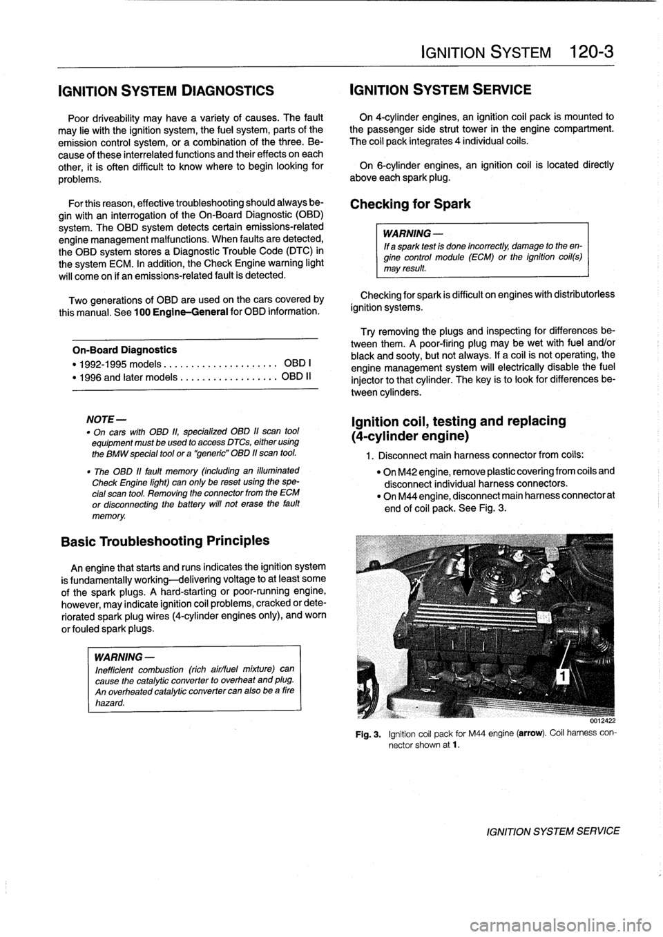
Fig
.
3
.
Ignition
coil
pack
for
M44
engine
(arrow)
.
Coil
harness
con-
nector
shown
at1
.
IGNITION
SYSTEM
SERVICE
Page 128 of 759
120-
4
IGNITION
SYSTEM
2
.
Check
for
battery
voltage
o
cofs
.
If
voltage
is
not
Table
b
.
Ignition
Coil
Resistance
present,
check
wire
between
terminal
15
and
ignition
(M42
Engine)
switch
.
See
Electrical
Wiring
Diagrams
.
"
On
M42
engine,
connect
digital
multimeter
between
ter-
minal
15(+)
in
each
harness
connector
and
ground
.
See
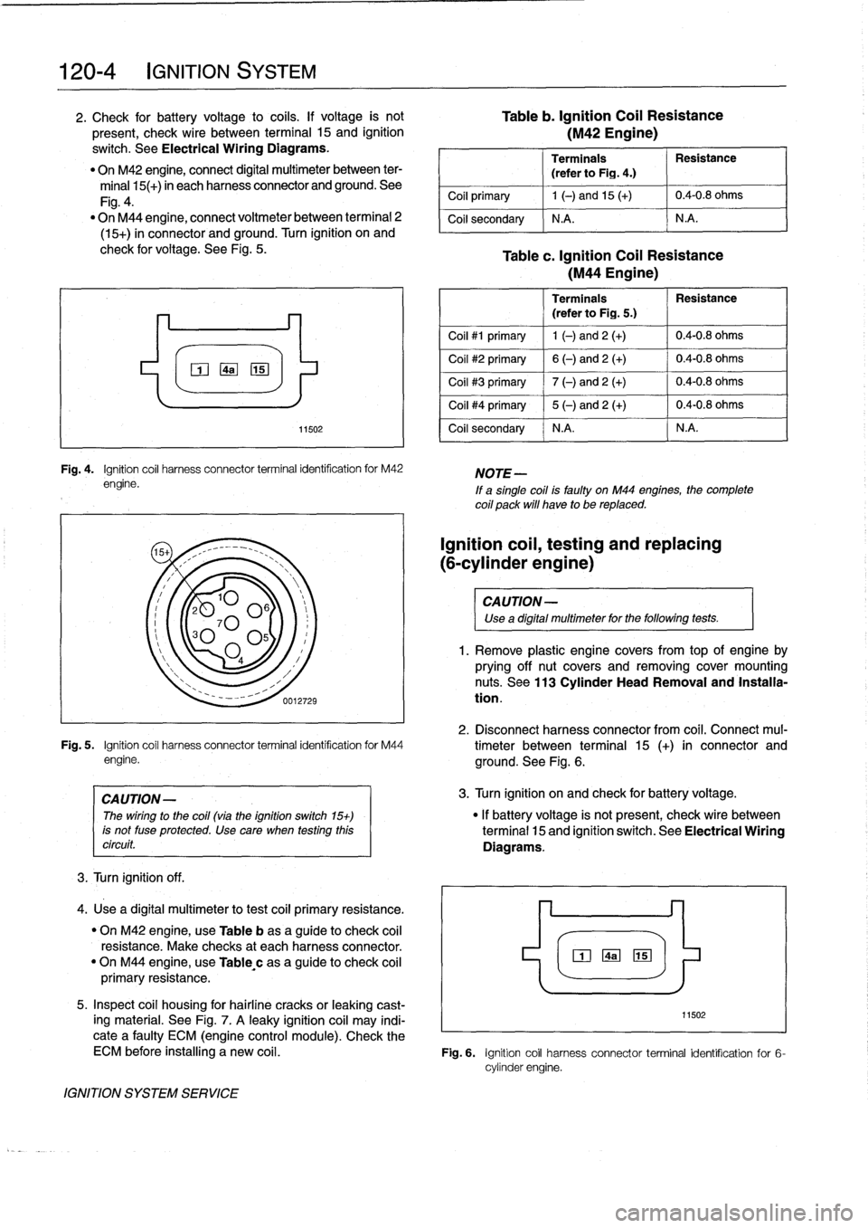
Fig
.
4
.
"
On
M44
engine,
connect
voltmeter
between
terminal
2
(15+)
in
connector
and
ground
.
Turn
ignition
on
and
check
for
voltage
.
See
Fig
.
5
.
3
.
Turn
ignition
off
.
0
4a15
Fig
.
4
.
Ignition
coil
harness
connector
terminal
identification
for
M42
engine
.
Fig
.
5
.
Ignition
coil
harness
connector
terminal
identification
for
M44
engine
.
CAUTION-
The
wiring
to
the
coil(via
the
ignition
switch
15+)
is
not
fuse
protected
.
Use
care
when
testing
thiscircuit
.
4
.
Use
a
digital
multimeter
totest
coil
primary
resistance
.
"
On
M42
engine,
use
Table
b
asa
guide
to
check
coil
resistance
.
Make
checks
at
each
harness
connector
.
"
On
M44
engine,
use
Table,c
as
a
guide
to
check
coil
primary
resistance
.
5
.
Inspect
coil
housing
for
hairline
cracks
or
leaking
cast-
ing
material
.
See
Fig
.
7
.
A
leaky
ignition
coil
may
indi-
11502
cate
a
faulty
ECM
(engine
control
module)
.
Check
the
ECM
before
installing
a
new
coil
.
Fig
.
6
.
Ignition
coil
harnessconnector
terminal
identification
for
6-
cylinder
engine
.
IGNITION
SYSTEM
SERVICE
11502
Terminals
Resistance
(refer
to
Fig
.
4
.)
Coil
primary
1
(-)
and
15
(+)
10
.4-0
.8
ohms
Coil
secondary
N
.A
.
N
.A
.
Table
c
.
Ignition
Coil
Resistance
(M44
Engine)
Terminais
Resistance
(referto
Fig
.
5
.)
Coil
#1
primary
1
(-)
and
2
(+)
0
.4-0
.8
ohms
Coil
#2
primary
6
(-)
and2
(+)
0
.4-0
.8
ohms
Coil
#3
primary
7
(-)
and
2
(+)
0
.4-0
.8
ohms
Coil
#4
primary
5
(-)
and2
(+)
0
.4-0
.8
ohms
Coil
secondary
N
.A
.
N
.A
.
NOTE-
If
a
single
coilís
faulty
on
M44
engines,
the
complete
coil
pack
will
have
to
be
replaced
.
Ignition
coil,
testing
and
replacing
(6-cylinder
engine)
CAUTION-
Use
a
digital
multimeter
for
the
following
tests
.
1.
Remove
plastic
enginecovers
from
top
of
engine
by
prying
off
nut
covers
and
removingcover
mounting
nuts
.
See
113
Cylinder
HeadRemoval
and
Installa-
tion
.
2
.
Disconnect
harnessconnectorfromcof
.
Connect
mul-
timeter
between
terminal
15
(+)
in
connector
and
ground
.
See
Fig
.
6
.
3
.
Turn
ignition
on
and
check
for
batteryvoltage
.
"
If
batteryvoltage
is
not
present,
check
wire
between
terminal
15
and
ignition
switch
.
See
Electrical
Wiring
Diagrams
.
"mozo