relay BMW M3 1995 E36 Owner's Manual
[x] Cancel search | Manufacturer: BMW, Model Year: 1995, Model line: M3, Model: BMW M3 1995 E36Pages: 759
Page 158 of 759
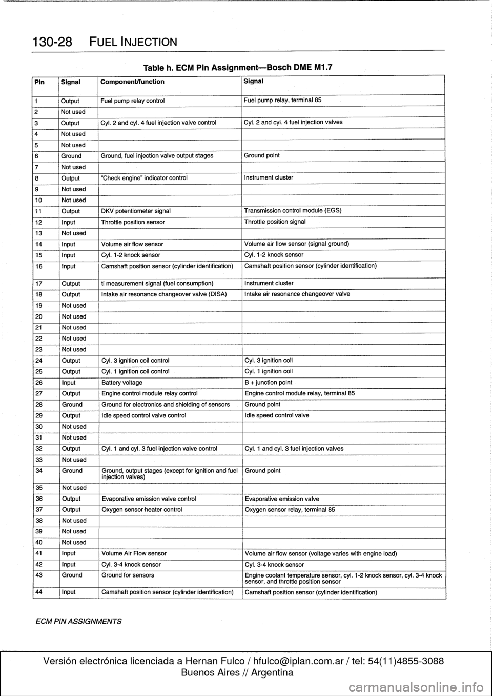
130-
1
2
FUEL
INJECTION
Fig
.
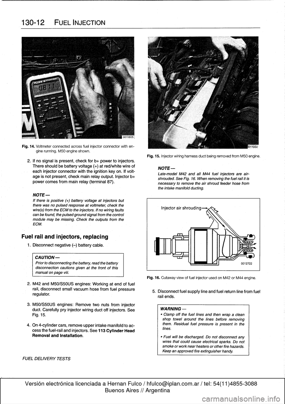
14
.
Voitmeter
connected
across
fuel
injector
connector
with
en-
gine
running
.
M50
engine
shown
.
2
.
If
no
signal
is
present,
check
for
b+
power
to
injectors
.
There
should
be
battery
voltage
(+)
at
red/whitewire
of
each
injector
connector
with
the
ignition
key
on
.
If
volt-
age
is
not
present,
check
main
relay
output
.
Injector
b+
power
comes
from
main
relay
(terminal
87)
.
NOTE-
If
there
is
positive
(+)
batteryvoltage
at
injectors
but
there
was
no
pulsedresponse
at
voltmeter,
check
the
wire(s)
from
the
ECM
to
the
injectors
.
If
no
wiring
faults
can
be
found,
the
pulsed
ground
signal
from
the
control
module
may
be
missing
.
Check
the
outputs
from
the
ECM
.
Fuel
rail
and
injectors,
replacing
1
.
Disconnect
negative
(-)
battery
cable
.
CAUTION-
Prior
to
disconnectiog
the
battery,
read
the
battery
disconnection
cautions
given
at
the
tront
of
this
manual
on
page
viii
.
2
.
M42
and
M50/S50US
engines
:
Working
at
end
offuel
rail,
disconnect
small
vacuum
hose
from
fuel
pressure
regulator
.
3
.
M50/S50US
engines
:
Remove
two
nuts
from
injector
duct
.
Carefully
pry
injector
wiring
duct
off
ínjectors
.
See
Fig
.
15
.
4
.
On
4-cylinder
cars,
remove
upper
intake
manifold
to
ac-
cess
the
fuel-rail
and
injectors
.
See
113
Cylinder
Head
Removal
and
Installation
.
FUELDELIVERYTESTS
Fig
.
15
.
Injector
wiring
harness
duct
being
removed
from
M50
engine
.
NOTE
-
Late-model
M42
and
all
M44
fuel
injectors
are
afr-
shrouded
.
See
Fig
.
16
.
When
removing
the
fuel
rail
it
is
necessary
to
remove
the
air
shroud
feeder
hose
from
the
intake
manifold
ducting
.
Fig
.
16
.
Cutaway
view
of
fuelinjector
usedon
M42
or
M44
engine
.
5
.
Disconnect
fuel
supply
line
and
fuel
retum
line
from
fuel
rail
ends
.
WARNING
-
"
Clamp
off
the
fuel
lines
and
then
wrapa
clean
shop
towei
around
the
lines
before
removing
them
.
Residual
fuel
pressure
is
present
in
the
lines
.
"
Fuel
will
be
discharged
.
Do
not
disconnect
any
wires
that
could
cause
electrical
sparks
.
Do
not
smoke
or
worknear
heaters
or
other
fire
hazards
.
Keepan
approved
fire
extinguisher
handy
.
Page 160 of 759
130-
1
4
FUEL
INJECTION
NOTE-
Be
sure
to
retrieve
thrust
washer
behind
fuel
pressure
regulator
on
6-cylinder
engine
.
4
.
Installation
is
reverse
of
removal
.
Replace
O-rings
.
Fuel
pressure
regulator,
replacing
(under
car
mount)
WARNING
-
Fuel
will
be
discharged
.
Do
not
disconnect
any
wires
that
could
cause
electrical
sparks
.
Do
not
smoke
or
work
near
heaters
or
other
fire
hazards
.
Keep
an
approved
tire
extinguisher
handy
.
On
late
4-
and
6-cylinder
cars,
the
fuel
pressure
regulator
is
mounted
beneath
the
left
sideof
the
car,
under
a
protective
cover
.
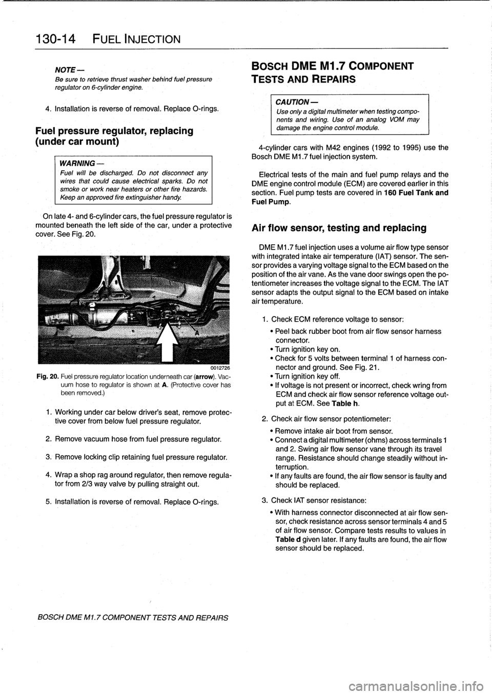
See
Fig
.
20
.
0012726
Fig
.
20
.
Fuel
pressure
regulatorlocation
underneath
car
(arrow)
.
Vac-
uum
hose
to
regulator
is
shown
at
A
.
(Protective
cover
has
been
removed
.)
5
.
Installation
is
reverse
of
removal
.
Replace
O-rings
.
BOSCH
DME
Ml
.
7
COMPONENT
TESTS
AND
REPAIRS
BOSCH
DME
Ml
.7
COMPONENT
TESTS
AND
REPAIRS
CA
UTION-
Use
only
a
digital
multimeter
when
testing
compo-
nents
and
wiring
.
Use
of
an
analog
VOM
may
damage
the
engine
control
module
.
4-cylinder
cars
with
M42
engines(1992
to
1995)use
the
Bosch
DME
M1
.7
fuel
injection
system
.
Electrical
tests
of
the
main
and
fuel
pump
relays
and
the
DME
engine
control
module
(ECM)
are
covered
earlier
in
this
section
.
Fuel
pump
tests
arecovered
in
160
Fuel
Tank
and
Fuel
Pump
.
Air
flow
sensor,
testing
and
replacing
DME
M1
.7
fuel
injection
uses
a
volume
air
flow
type
sensor
with
integrated
intake
air
temperature
(IAT)
sensor
.
The
sen-
sor
provides
a
varyingvoltage
signal
to
the
ECM
based
on
the
position
of
the
air
vane
.
As
the
vane
doorswings
open
thepo-
tentiometer
increases
the
voltage
signal
to
the
ECM
.
The
IATsensor
adapts
theoutput
signal
to
the
ECM
based
on
intake
air
temperature
.
1
.
Check
ECM
reference
voltage
to
sensor
:
"
Peel
back
rubber
boot
from
air
flow
sensor
harness
connector
.
"
Turn
ignition
keyon
.
"
Check
for
5
volts
between
terminal
1
of
harness
con-
nector
and
ground
.
See
Fig
.
21
.
"
Turn
ignition
key
off
.
"
If
voltage
is
not
present
or
incorrect,
check
wring
from
ECM
and
check
air
flow
sensor
reference
voltage
out-
put
at
ECM
.
See
Table
h
.
1
.
Working
under
car
below
driver's
seat,
remove
protec-
tive
cover
from
below
fuel
pressure
regulator
.
"
Remove
intake
air
bootfrom
sensor
.
2
.
Remove
vacuum
hosefrom
fuel
pressure
regulator
.
"
Connect
a
digital
multimeter
(ohms)
across
terminais
1
and
2
.
Swing
air
flow
sensor
vane
through
its
travel
3
.
Remove
locking
clip
retaining
fuel
pressure
regulator
.
range
.
Resistance
should
change
steadily
without
in-
terruption
.
4
.
Wrap
a
shop
rag
around
regulator,
then
remove
regula-
"
If
any
faults
are
found,
the
air
flow
sensor
is
faulty
and
tor
from
213
way
valve
by
pullingstraight
out
.
should
be
replaced
.
2
.
Check
air
flow
sensor
potentiometer
:
3
.
Check
IAT
sensor
resistance
:
"
With
harness
connector
disconnected
at
air
flow
sen-
sor,
check
resistance
across
sensor
terminais
4
and
5
of
air
flow
sensor
.
Compare
tests
results
to
values
in
Table
d
given
later
.
If
any
faults
are
found,
the
air
flow
sensor
should
be
replaced
.
Page 162 of 759
130-
1
6
FUEL
INJECTION
Throttie
position
sensor
(TPS),
Idie
speed
control
valve,
testing
and
replacing
testing
and
replacing
The
throttie
position
sensor
(TPS)
is
mounted
on
the
side
of
¡die
speed
is
maintained
by
the
ECM
via
the
¡die
speed
con-
the
throttie
housing
and
is
directly
connected
to
the
throttie
trol
valve
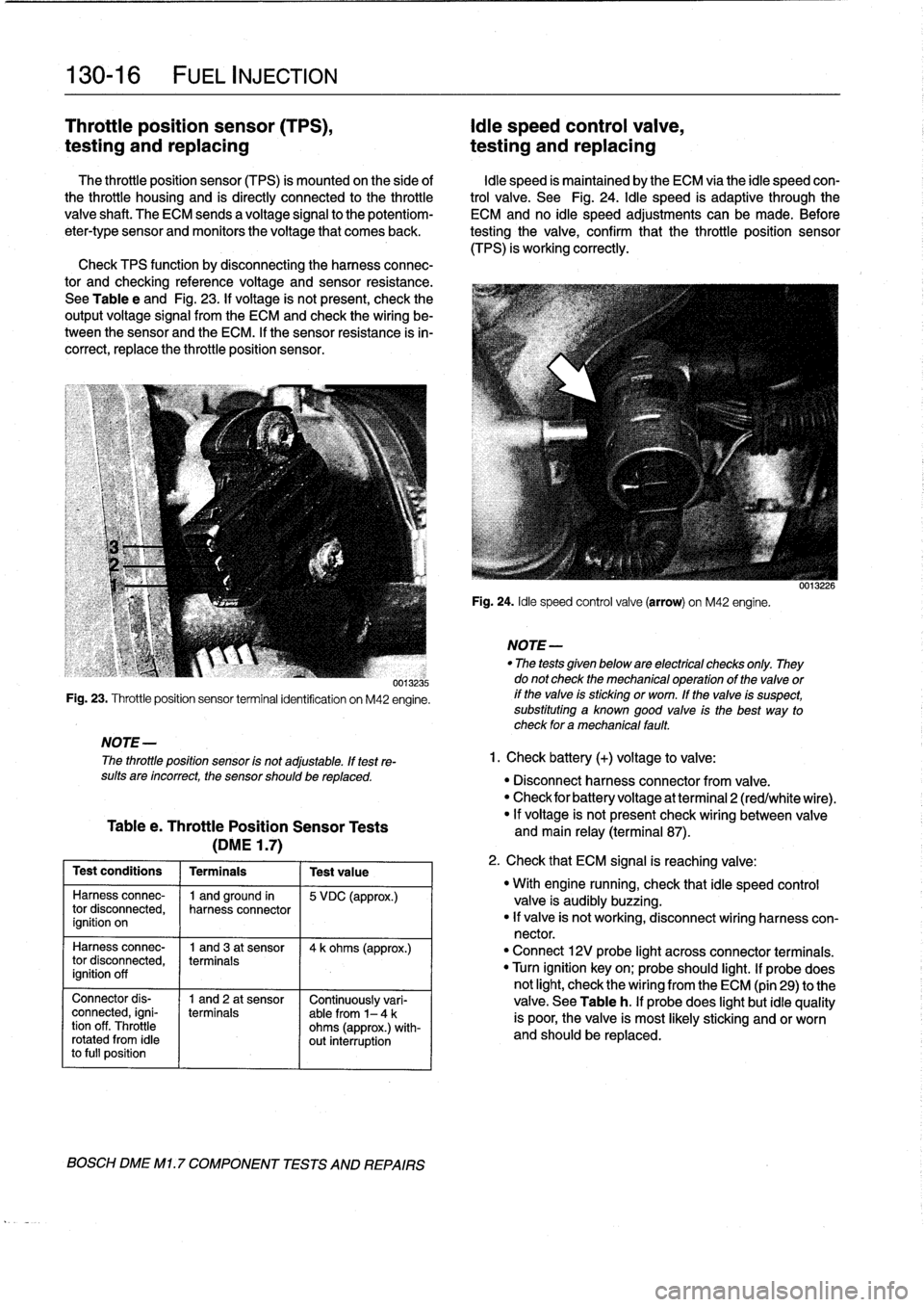
.
See
Fig
.
24
.
¡die
speed
is
adaptive
through
the
valve
shaft
.
The
ECM
sends
a
voltage
signal
to
the
potentiom-
ECM
and
no
¡die
speed
adjustments
can
be
made
.
Before
eter-type
sensor
and
monitors
the
voltage
that
comes
back
.
testing
the
valve,
confirm
that
the
throttie
position
sensor(TPS)
is
working
correctly
.
Check
TPS
function
by
disconnecting
the
harnessconnec-
tor
and
checking
reference
voltage
and
sensor
resistance
.
See
Table
e
and
Fig
.
23
.
If
voltage
is
not
present,
check
the
output
voltage
signal
from
the
ECM
and
check
the
wiring
be-
tween
the
sensor
and
the
ECM
.
If
the
sensor
resistance
is
in-
correct,
replace
the
throttie
position
sensor
.
NOTE
-
The
throttie
position
sensor
is
not
adjustable
.
If
test
re-
sults
are
íncorrect,
the
sensor
should
be
replaced
.
Table
e
.
Throttle
Position
Sensor
Tests
(DME
1
.7)
Testconditions
1
Terminais
1
Test
value
Harness
connec-
(
1
and
ground
in
15
VDC
(approx
.)
tor
disconnected,
harness
connector
ignition
on
0013235
Fig
.
23
.
Throttieposition
sensor
terminal
identification
on
M42
engine
.
Harnessconnec-
I
1
and
3
at
sensor
(
4k
ohms
(approx
.)
tor
disconnected,
terminais
ignition
off
Connector
dis-
1
and
2
at
sensor
Continuously
vari-
connected,
igni-
terminais
able
from
1-4
k
tion
off
.
Throttle
ohms
(approx
.)
with
rotated
from
¡die
out
interruption
to
fui]
position
BOSCH
DME
Ml
.
7
COMPONENT
TESTS
AND
REPAIRS
Fig
.
24
.
¡die
speed
control
valve
(arrow)
on
M42
engine
.
NOTE
-
"
The
tests
given
below
are
electrical
checks
only
.
They
do
not
check
the
mechanical
operation
of
the
valve
or
if
the
valve
is
sticking
or
worn
.
If
the
valve
is
suspect,
substituting
a
known
good
valve
is
the
best
way
to
check
for
amechanical
fault
.
1
.
Check
battery
(+)
voltage
to
valve
:
0013226
"
Disconnect
harness
connector
from
valve
.
"
Check
for
battery
voltage
at
terminal
2
(red/white
wire)
.
"
If
voltage
is
not
present
check
wiring
between
valve
and
main
relay
(terminal
87)
.
2
.
Check
that
ECM
signal
is
reaching
valve
:
"
With
engine
running,
check
that
¡die
speed
control
valve
is
audibly
buzzing
.
"
If
valve
is
not
working,
disconnect
wiring
harness
con-
nector
.
"
Connect
12V
probe
light
across
connector
terminais
.
"
Turn
ignition
key
on
;
probe
should
light
.
lf
probe
does
nof
light,
check
the
wiring
from
the
ECM
(pin
29)
to
the
valve
.
See
Table
h
.
lf
probe
does
light
but
¡die
quality
is
poor,
the
valve
is
most
likely
sticking
and
or
worn
and
should
be
replaced
.
Page 163 of 759
BOSCH
DME
MM
AND
M33
.1
COMPONENT
TESTS
AND
REPAIRS
Consult
Table
a
for
engine
application
information
for
the
Bosch
DME
3
.1
and
3
.3.1
systems
.
The
DME
3
.1
and
DME
3
.3
.1
systems
are
similar
in
opera-
tion,
with
knock
control
and
VANOS
operation
being
the
key
differences
.
DME
3
.1
engines
arenot
equipped
with
VANOS
or
knock
detectors,
while
the
DM
E3
.3
.1
system
is
.
CA
UTION-
Use
onty
a
digital
multimeter
when
testing
wiring
.
Use
of
an
analog
VOM
may
damage
the
engine
control
module
.
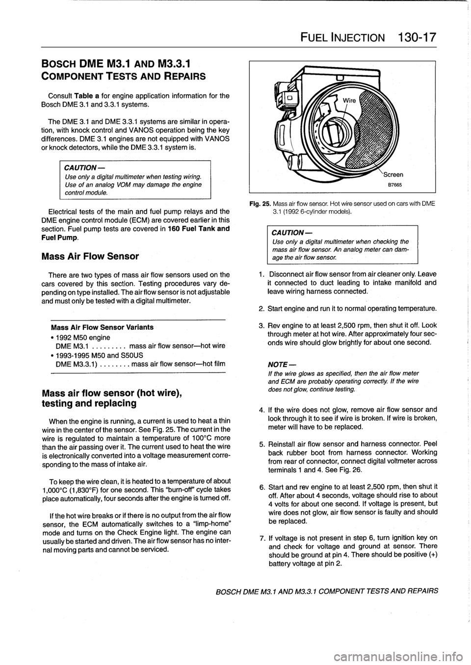
Fig
.
25
.
Mass
air
flow
sensor
.
Hot
wire
sensor
usedon
carswith
DME
Electrical
tests
of
the
main
and
fuel
pump
relays
and
the
3
.1
(1992
6-cylinder
models)
.
DME
engine
control
module
(ECM)
are
covered
earlier
in
this
section
.
Fuel
pump
tests
are
covered
in
160
Fuel
Tank
and
CAUTION-
Fuel
Pump
.
Use
only
a
digital
multimeter
when
checking
the
mass
air
flow
sensor
.
An
analog
meter
can
dam-
Mass
Air
Flow
Sensor
age
theair
flow
sensor
.
There
are
two
types
of
mass
air
flow
sensors
used
onthe
1
.
Disconnect
air
flow
sensor
from
air
cleaner
only
.
Leave
cars
covered
by
this
section
.
Testing
procedures
vary
de-
it
connected
to
duct
leading
to
intake
manifold
and
pending
on
type
installed
.
The
airflow
sensor
is
not
adjustable
leave
wiring
harness
connected
.
and
must
only
be
tested
with
a
digital
multimeter
.
Mass
Air
FlowSensor
Variants
"
1992
M50
engine
DME
M3
.1
.
.
.
.
...
..
mass
air
flow
sensor-hot
wire
"
1993-1995
M50
and
S50US
DMEM33
.1)
.
...
...
.
mass
air
flow
sensor-hot
film
Mass
air
flow
sensor
(hot
wire),
testing
and
replacing
When
the
engine
is
running,
a
current
is
used
to
heat
a
thin
wire
in
the
center
of
the
sensor
.
See
Fig
.
25
.
The
current
in
the
wire
is
regulated
to
maintain
a
temperature
of
100°C
more
than
the
air
passing
over
it
.
The
current
used
to
heat
the
wire
is
electronically
conneced
into
a
voltage
measurement
corre-
sponding
to
the
mass
of
intake
a¡
r
.
To
keep
the
wire
clean,
it
is
heated
to
a
temperature
of
about
1,000°C
(1,830°F)
for
one
second
.
This
"burn-off"
cycle
takes
place
automatically,
four
seconds
after
the
engine
is
tumed
off
.
lf
thehot
wire
breaks
or
if
there
is
no
output
from
the
air
flow
sensor,
the
ECM
automatically
switches
to
a
"limp-home"
mode
and
tucos
on
the
Check
Engine
light
.
The
engine
can
usually
be
started
and
driven
.
The
air
flow
sensor
has
no
inter-
nal
moving
parts
and
cannot
be
serviced
.
FUEL
INJECTION
130-
1
7
2
.
Start
engine
and
run
it
to
normal
operating
temperature
.
3
.
Rev
engine
toat
least
2,500
rpm,then
shut
it
off
.
Look
through
meter
at
hot
wire
.
After
approximately
four
sec-
onds
wire
should
glow
brightly
for
about
one
second
.
NOTE
-
If
the
wire
glowsas
specified,
then
the
airflow
meter
and
ECM
are
probably
operating
correctly
.
lf
the
wire
does
not
glow,
continue
testing
.
4
.
lf
the
wire
does
not
glow,
remove
air
flow
sensor
and
look
through
it
to
see
if
wire
is
broken
.
lf
wire
is
broken,
meter
will
have
to
be
replaced
.
5
.
Reinstall
air
flow
sensor
and
harness
connector
.
Peel
back
rubber
bootfrom
harness
connector
.
Working
from
rear
of
connector,
connect
digital
voltmeter
across
terminals
1
and
4
.
See
Fig
.
26
.
6
.
Start
and
rev
engine
toat
least
2,500
rpm,thenshut
it
off
.
After
about
4
seconds,
voltage
should
riseto
about
4
volts
for
about
one
second
.
lf
voltage
is
present,
but
wire
does
not
glow,
air
flow
sensor
is
faulty
and
should
be
replaced
.
7
.
lf
voltage
is
not
present
in
step
6,
turn
ignition
key
on
and
check
for
voltage
and
ground
at
sensor
.
There
should
beground
at
pin
4
.
There
should
be
positive
(+)
battery
voltage
at
pin
2
.
BOSCH
DME
M3
.1
AND
M32
.1
COMPONENT
TESTS
AND
REPAIRS
Page 164 of 759
130-18
FUEL
INJECTION
The
engine
coolant
temperature
(ECT)
sensor
sends
con-
tinuous
engine
coolant
temperature
information
to
the
ECM
.
Fig
.
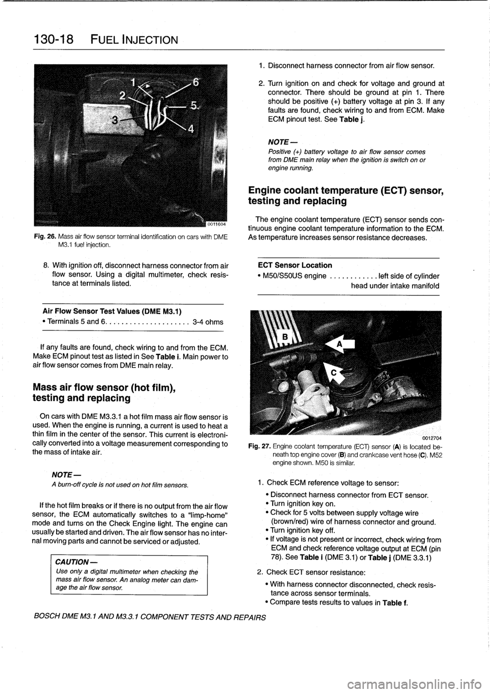
26
.
Mass
air
flow
sensor
terminalidentifcation
on
carswith
DME
As
temperature
increases
sensor
resistance
decreases
.
M3
.1
fuel
injection
.
Mass
air
flow
sensor
(hot
film),
testing
and
replacing
MOTE-
A
burn-off
cycle
is
not
used
on
hot
film
sensors
.
8
.
With
ignition
off,
disconnect
harness
connector
from
air
ECT
Sensor
Location
flow
sensor
.
Using
a
digital
multimeter,
check
resis-
"
M50/S50US
engine
............
left
side
of
cylinder
tance
at
terminals
listed
.
head
under
intake
manifold
Air
Flow
Sensor
Test
Values
(DMEM3
.1)
"
Terminals
5
and
6
.
.
.
.........
..
.
..
....
3-4
ohms
If
any
faults
are
found,
check
wiring
lo
and
from
the
ECM
.
Make
ECM
pinout
test
as
listed
in
See
Table
i
.
Main
power
to
air
flow
sensor
comes
from
DME
main
relay
.
On
cars
with
DME
M3
.3
.1
a
hot
film
mass
air
flow
sensor
is
used
.
When
the
engine
is
running,
a
current
is
used
lo
heat
a
thinfilm
in
the
center
of
the
sensor
.
This
current
is
electroni-
cally
converted
into
a
voltage
measurement
corresponding
to
the
mass
of
intake
air
.
If
thehot
film
breaks
or
if
there
is
no
output
from
the
air
flow
sensor,
the
ECM
automatically
switches
to
a
"limp-home"
mode
and
tucos
on
the
Check
Engine
light
.
The
engine
can
usually
be
started
and
driven
.
The
air
flow
sensor
has
no
inter-
nal
moving
parts
and
cannot
be
senricedor
adjusted
.
CA
UTION-
Use
only
a
digital
multimeter
when
checking
the
mass
air
flow
sensor
.
An
analogmetercan
dam-
age
the
air
flow
sensor
.
BOSCH
DME
M3
.
1
AND
M32
.1
COMPONENT
TESTS
AND
REPAIRS
1
.
Disconnect
harnessconnector
from
air
flow
sensor
.
2
.
Turn
ignition
on
and
check
for
voltage
and
ground
at
connector
.
There
should
beground
at
pin
1
.
There
should
be
positive
(+)
battery
voltage
at
pin
3
.
If
any
faults
are
found,
check
wiring
to
and
from
ECM
.
Make
ECM
pinout
test
.
See
Table
j
.
NOTE-
Positive
(+)
battery
voltage
to
air
flow
sensor
comes
from
DME
main
relay
when
the
ignition
is
switch
on
orengine
running
.
Engine
coolant
temperature
(ECT)
sensor,
testing
and
replacing
0012704
Fig
.
27
.
Engine
coolant
temperature
(ECT)
sensor
(A)
is
located
be-
neath
top
engine
cover
(B)
and
crankcase
vent
hose
(C)
.
M52
engine
shown
.
M50
is
similar
.
1
.
Check
ECM
reference
voltage
to
sensor
:
"
Disconnect
harnessconnector
from
ECT
sensor
.
"
Turn
ignition
keyon
.
"
Check
for
5
volts
between
supply
voltage
wire
(brown/red)
wire
of
harness
connector
and
ground
.
"
Turn
ignition
key
off
.
"
If
voltage
is'
not
present
or
incorrect,
check
wiring
from
ECM
and
check
referencevoltage
output
at
ECM
(pin
78)
.
See
Table
i
(DM
E
3
.1)
or
Table
j
(DME
3
.3
.1)
2
.
Check
ECT
sensor
resistance
:
"
With
harnessconnector
disconnected,
check
resis-
tance
acrosssensor
terminals
.
"
Compare
tests
results
to
values
in
Table
f
.
Page 166 of 759
130-20
FUEL
INJECTION
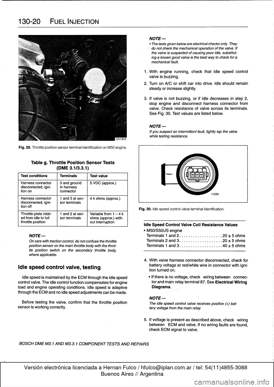
Fig
.
29
.
Throttleposition
sensor
terminal
identification
on
M50
engine
.
Tableg
.
Throttle
Position
Sensor
Tests
(DME3
.113
.3
.1)
Test
conditions
I
Terminals
I
Testvalue
Harness
connector
13
andground
15
VDC
(approx
.)
disconnected,
igni-
in
harness
tion
on
connector
Harness
connector
1
and3
at
sen-
14
k
ohms
(approx
.)
disconnected,
igni-
sor
terminals
tion
off
Throttle
plate
rotat-
1
and
2
at
sen-
Variable
from
1
-
4ked
from
¡dieto
full
sor
terminals
ohms
(approx
.)
with-
throttle
position
out
interruption
¡die
Speed
Control
Valve
Coil
Resistance
Values
"
M50/S50US
engine
NOTE-
Terminals
1
and
2
..
.
................
20
t
5
ohms
On
cars
with
tractioncontrol,
do
not
confuse
the
throttle
Terminals
2
and
3
...................
20
t5
ohms
position
sensor
on
the
main
throttle
body
with
the
throt-
Terminals
1
and
3
..
.
..
:
............
.40
t
5
ohms
tle
positionswitch
on
the
secondary
throttle
body,
where
applicable
.
¡die
speed
control
valve,
testing
¡die
speed
is
maintained
by
the
ECM
through
the
¡die
speed
control
valve
.
The
¡die
controlfunction
compensates
for
engine
load
and
engine
operating
conditions
.
¡die
speed
is
adaptive
through
the
ECM
and
no
¡die
speed
adjustments
can
be
made
.
NOTE-
Before
testing
the
valve,
confirm
that
the
throttle
position
The
idle
speed
controlvalve
receives
positive
(+)
bat-
sensor
is
working
correctly
.
tery
voltage
from
the
main
relay
.
BOSCH
DME
M3
.
1
AND
M3
.3
.1
COMPONENT
TESTS
AND
REPAIRS
NOTE-
"
The
tests
given
below
are
electrical
checks
only
.
They
do
not
check
the
mechanical
operation
of
the
valve
.
If
the
valve
is
suspected
of
causing
poor
idie,
substitut-
ing
a
known
good
valve
is
the
best
way
to
check
for
a
mechanical
fault
.
1
.
With
engine
running,
check
that
¡die
speed
control
valve
is
buzzing
.
2
.
Turn
on
A/C
or
shift
car
finto
drive
.
¡die
should
remain
steady
orincrease
slightly
.
3
.
If
valve
is
not
buzzing,or
if
¡die
decreases
in
step
2,
stop
engine
and
disconnect
harness
connector
from
valve
.
Check
resistance
of
valve
across
its
terminals
.
See
Fig
.
30
.
Test
values
are
listed
below
.
NOTE
-
If
you
suspect
an
intermittent
fault,
lightly
tapthe
valve
while
testing
resistance
.
11250
Fig
.
30
.
¡die
speed
control
valve
terminal
identification
.
4
.
With
valve
harnessconnector
disconnected,
check
for
battery
voltage
at
red/white
wire
in
connector
with
igni-
tion
tumed
on
.
"
If
there
is
no
voltage,
check
wiring
between
connec-
tor
and
main
relayterminal
87
.
See
Electrical
Wiring
Diagrams
.
5
.
If
voltage
is
presentas
described
above,
check
wiring
between
ECM
and
valve
.
If
no
wiring
faults
are
found,
check
ECM
signal
to
valve
.
Page 170 of 759
130-24
FUEL
INJECTION
Jo
'0
o_A
í1
RELAY
..
.
.
CAMSHAFT
POSITION
SENSOR
'
.
~'
~
:UhI~IIUH~W~`bY~7~d~t~II7
.
.
.
,
1111111
~ilf
ASC
TERMINAL
15
MEMORY
POWER
CRANKSHAFT
POSITION
qtcMSENSOR
THROTTLE
POSITION
ENGINE
COOLANT
TEMP
FUELTANK
PRESSURE
SENSOR
S-EML
S-MSR
S-ASC
VEHICLE
SPEED
LOW
FUEL
LEVEL
A/C
SWITCH
ON
(AC)
E36
IHKA
COMPRESSOR
"ON"
SIGNAL
(KO)
INDIVIDUAL
SERIAL
NUMBER
SIEMENS
MS
41
.
1
COMPONENT
REPLACEMENT
FUEL
PUMP
RELAY
CONTROL
AUX
GROUND
P
MAIN
GROUND
AC
COMPRESSOR
RELAY
CONTROL
~®
SECONDARY
AIR
INJECTION
AIR
PUMP
RELAY
CONTROL
-
M
PRE
CAT
POST
CAT
m
nXYGEN
SENSOR
ys
U
~
4
,
HEATING
FUELINJECTOR
CONTROL
(
MS
41
.1
(
MS
PURGE
CONTROL
VALVE
//
PURGE
'
CANISTERSHUT-OFF
VALVE
ECM
RELAY
CONTROL
IGNITION
COILS
CONTROL
1
ASC
o
ayi
THROTTLE
POTENTIOMETER
POWER
,
al
;
..
i
r71a
.
"a
fn7111,
/
r
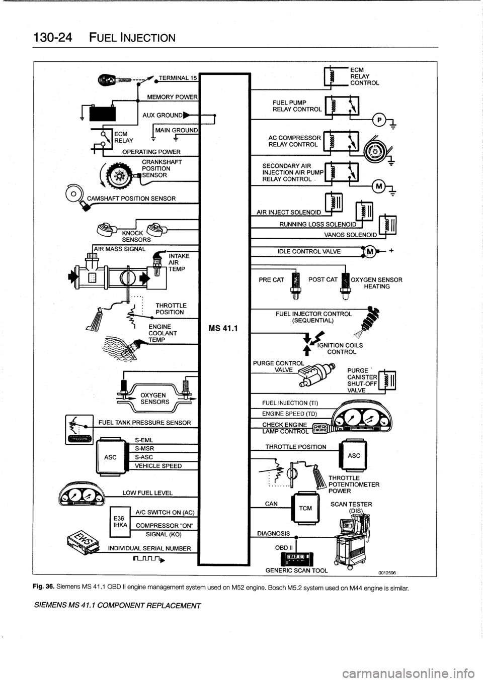
Fig
.
36
.
Siemens
MS
41
.1
OBD
II
engine
management
system
usedon
M52
engine
.
Bosch
M5
.2
systemusedon
M44
engine
is
similar
.
Page 173 of 759
0013ZIM
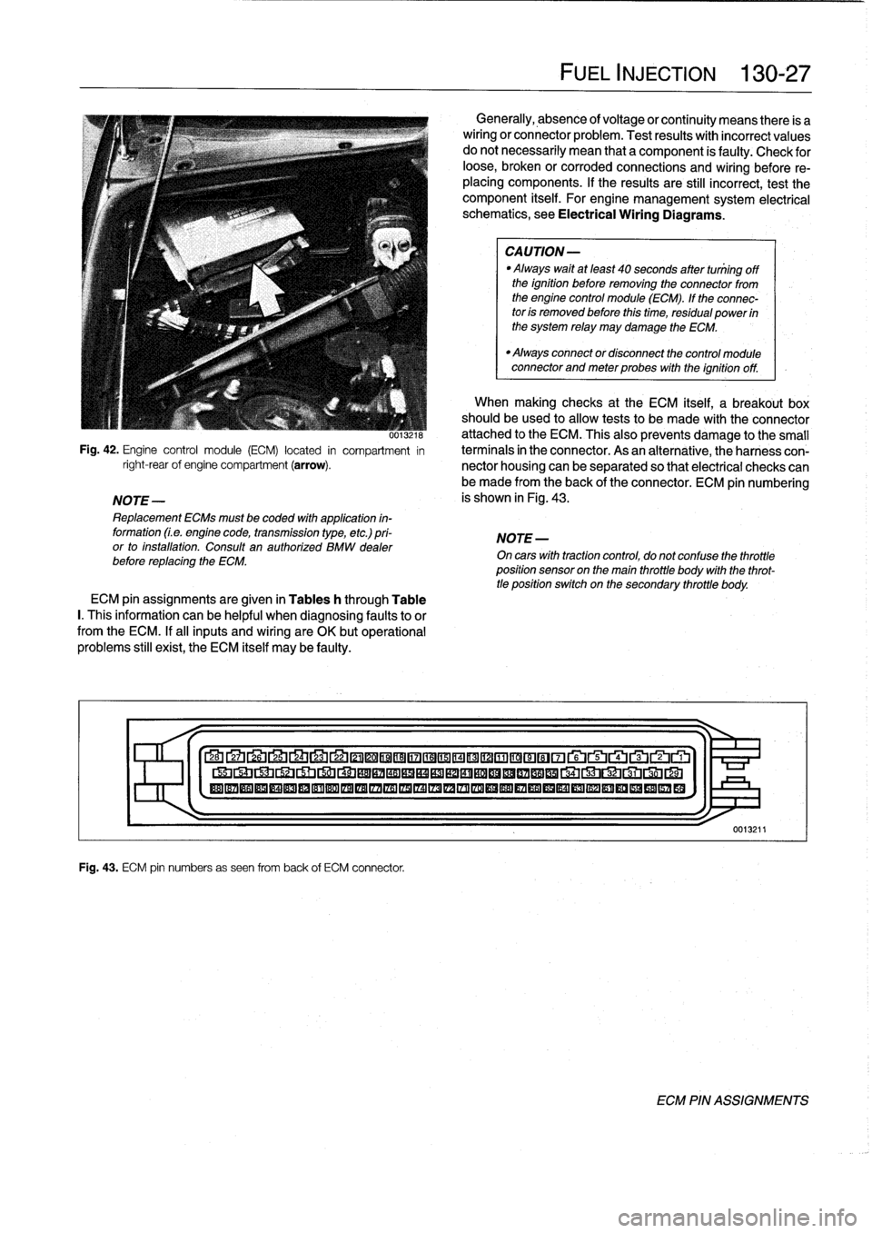
Fig
.
42
.
Engine
control
module
(ECM)
located
in
compartment
in
right-rearof
engine
compartment
(arrow)
.
NOTE-
Replacement
ECMs
must
be
coded
with
application
in-
formation
(Le
.
engine
code,
transmission
type,
etc
.)
pri-
or
to
installation
.
Consult
an
authorized
BMW
dealer
before
replacing
the
ECM
.
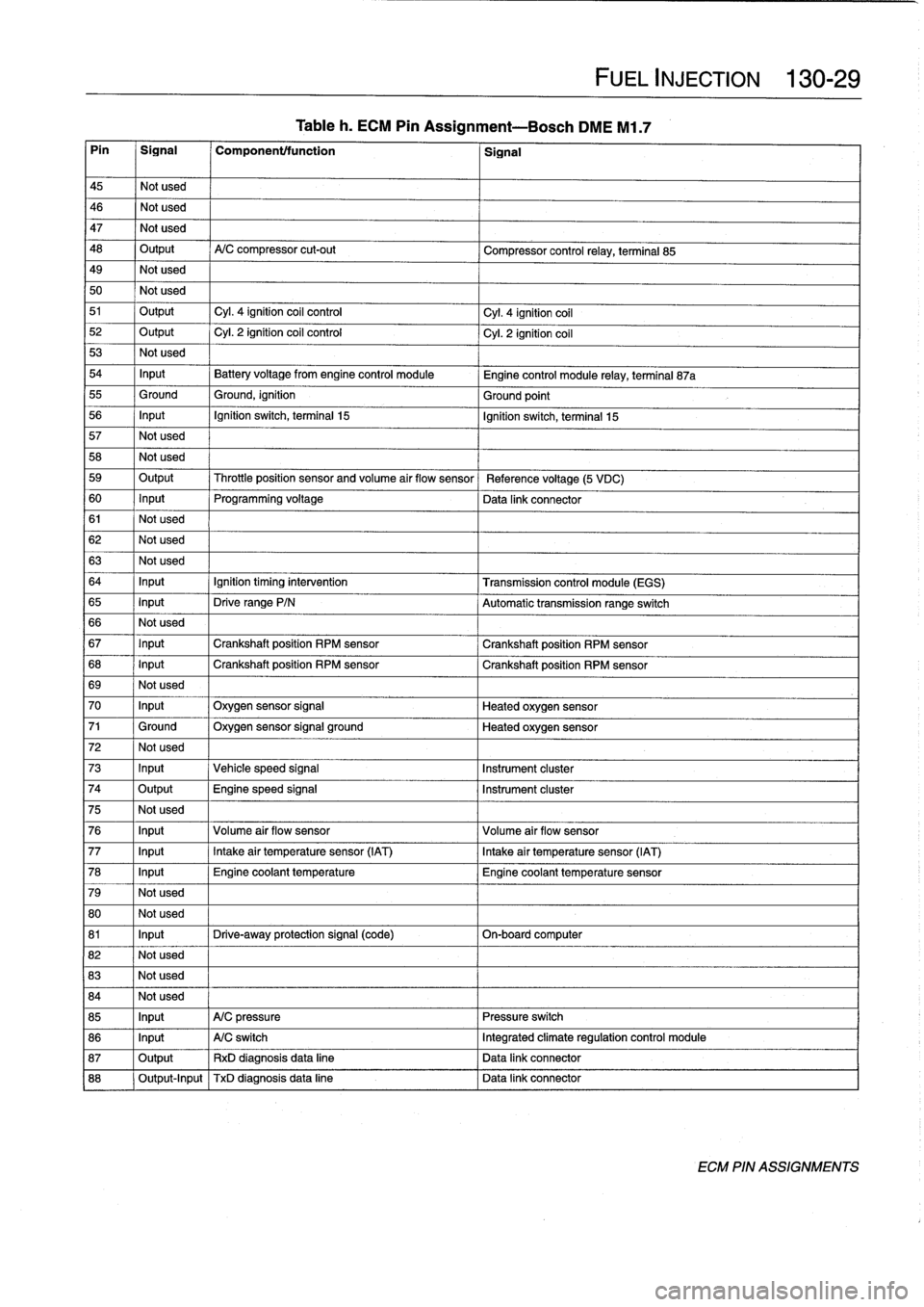
ECM
pin
assignments
are
given
in
Tables
h
through
Table
I.
This
information
can
be
helpful
when
diagnosing
faultsto
or
from
the
ECM
.
If
al¡
inputs
and
wiring
are
OK
butoperational
problems
still
exist,
the
ECM
itself
may
be
faulty
.
Fig
.
43
.
ECM
pin
numbers
as
seen
from
back
of
ECM
connector
.
FUEL
INJECTION
130-
2
7
Generally,
absence
of
voltage
or
continuity
means
there
is
a
wiring
or
connector
problem
.
Test
results
with
incorrect
values
do
notnecessarily
mean
that
a
component
is
faulty
:
Check
for
loose,
broken
or
corroded
connections
and
wiring
before
re-
placing
components
.
If
the
results
are
still
incorrect,
test
the
component
itself
.
For
engine
management
system
electrical
schematics,
see
Electrical
Wiring
Diagrams
.
CAUTION-
Always
waitat
least
40
seconds
after
tuniing
off
the
ignition
before
removing
the
connector
from
the
engine
control
module
(ECM)
.
If
the
connec-
tor
is
removed
before
this
time,
residual
power
in
the
system
relay
may
damage
the
ECM
.
"
Always
connector
disconnect
the
control
module
connector
and
meter
probes
with
the
ignitionoff
.
When
making
checks
at
the
ECM
itself,
a
breakout
box
should
be
used
to
allow
tests
to
be
made
with
the
connector
attached
to
the
ECM
.
This
also
prevents
damage
tothe
small
termínals
in
the
connector
.
As
an
alternative,
theharness
con-
nector
housing
can
be
separated
so
that
electrical
checks
can
be
made
from
the
back
of
the
connector
.
ECM
pin
numbering
is
shown
in
Fig
.
43
.
NOTE
-
On
cars
with
tractioncontrol,
do
not
confuse
the
throttle
position
sensor
on
the
main
throttle
body
with
the
throt-
tle
position
switch
on
the
secondary
throttle
body
.
27
Lb
2L4
LJ
22
©©®®17
©©®©©~©©®©~~rui~~ru
®®®®®®®®®®®®®®®IZA®®®®®®®®®®®®®®®®®
1
>I-
0013211
ECM
PIN
ASSIGNMENTS
Page 174 of 759
130-
2
8
FUEL
INJECTION
Tableh
.
ECM
Pin
Assignment-Bosch
DME
M1
.7
Pin
Signal
Componenttfunction
Signal
1
Output
Fuel
pump
relay
control
Fuel
pump
relay,
terminal
85
2
Not
used
3
Output
Cyl
.
2
and
cyl
.
4
fuel
injection
valve
control
Cyl
.
2
and
cyl
.
4
fuel
injection
valves
4
Not
used
5
Not
used
6
Ground
Ground,
fuel
injection
valveoutputstages
Ground
point
7
Not
used
8
Output
"Check
engine"
indicator
control
Instrument
cluster
9
Not
used
10
Not
used
11
Output
DKV
potentiometer
signal
Transmission
control
module
(EGS)
12
Input
Throttleposition
sensor
Throttleposition
Signal
13
Not
used
14
Input
Volume
air
flow
sensor
Volume
air
flow
sensor
(signal
ground)
15
Input
Cyl
.
1-2
knock
sensor
Cyl
.
1-2
knock
sensor
16
Input
Camshaft
position
sensor
(cylinder
identification)
Camshaft
position
sensor
(cylinder
identification)
17
Output
ti
measurement
signal
(fuel
consumption)
Instrument
cluster
18
Output
Intakeair
resonance
changeover
valve
(DISA)
Intake
air
resonance
changeover
valve
19
-
Not
used
20
Not
used
21
Not
used
22
Not
used
23
Not
used
24
Output
Cyl
.
3
ignition
coil
control
Cyl
.
3
ignition
coil
25
Output
Cyl
.
1
ignition
coil
control
Cyl
.
1
ignition
coil
26
Input
Battery
voltage
B
+junction
point
27
Output
Engine
control
module
relay
control
Engine
control
module
relay,
terminal
85
28
Ground
Ground
for
electronics
and
shielding
of
sensors
Ground
point
29
Output
Idle
speed
control
valve
control
Idle
speed
control
valve
30
Not
used
31
Not
used
32
Output
Cyl
.
1
and
cyl
.
3
fuel
injection
valve
control
Cyl
.
1
and
cyl
.
3
fuel
injection
valves
33
Not
used
34
Ground
Ground,
output
stages
(except
for
ignition
and
fuel
Ground
point
injection
valves)
35
Not
used
36
Output
Evaporative
emissionvalve
control
Evaporative
emission
valve
37
Output
Oxygen
sensor
heater
control
Oxygen
sensor
relay,
terminal
85
38
Not
used
39
Not
used
40
I
Not
used
41
I
Input
,
Volume
Air
Flow
sensor
Volume
air
flow
sensor
(voltage
varies
with
engine
load)
42
1
Input
1
Cyl
.
3-4
knock
sensor
1
Cyl
.
3-4
knock
sensor
43
Ground
Ground
for
sensors
Engine
coolant
temperature
sensor,
cyl
.
1-2
knock
sensor,
cyl
.
3-4
knock
sensor,
and
throttle
position
sensor
44
1
Input
1
Camshaft
position
sensor
(cylinder
identification)
1
Camshaft
position
sensor
(cylinder
identification)
ECM
PIN
ASSIGNMENTS
Page 175 of 759
Tableh
.
ECM
Pin
Assignment--Bosch
DME
M1
.7
Pin
1
Signal
1
Component/function
1
Signal
45
Notused
46
Notused
47
Notused
48
Output
A/C
compressor
cut-out
Compressor
control
relay,
terminal
85
49
Notused
50
Notused
51
Output
Cyl
.
4
ignition
coil
control
Cyl
.
4
ignition
coil
52
Output
Cyl
.
2
ignition
coil
control
Cyl
.
2
ignition
coil
53
Not
used
54
Input
Battery
voltage
from
engine
control
module
Engine
control
module
relay,
terminal
87a
55
Ground
Ground,
ignition
Ground
point
56
Input
Ignition
switch,
terminal
15
Ignition
switch,
terminal
15
57
Notused
58
Not
used
59
Output
Throttleposition
sensor
and
volume
air
flow
sensor
Reference
voltage
(5
VDC)
60
Input
Programming
voltage
Data
link
connector
61
Notused
62
Notused
63
Notused
64
Input
Ignition
timing
intervention
Transmission
control
module
(EGS)
65
Input
Drive
range
P/N
Automatic
transmission
range
switch
66
Notused
67
Input
Crankshaft
position
RPM
sensor
Crankshaft
position
RPM
sensor
68
Input
Crankshaft
position
RPM
sensor
Crankshaft
position
RPM
sensor
69
Notused
70
Input
Oxygen
sensor
signal
Heated
oxygen
sensor
71
Ground
Oxygen
sensor
signal
ground
Heated
oxygen
sensor
72
Notused
73
Input
Vehicle
speed
signal
Instrument
cluster
74
Output
Engine
speed
signal
Instrument
cluster
75
Not
used
76
Input
Volume
air
flow
sensor
Volume
air
flow
sensor
77
Input
Intake
air
temperature
sensor
(IAT)
Intake
air
temperature
sensor
(IAT)
78
Input
Engine
coolant
temperature
Engine
coolant
temperature
sensor
79
Notused
80
Not
used
81
Input
Drive-away
protection
signal
(code)
On-boardcomputer
82
Not
used
83
Notused
84
Not
used
85
Input
A/C
pressure
Pressure
switch
86
Input
A/C
switch
Integrated
climate
regulation
control
module
87
Output
RxD
diagnosisdata
line
Data
link
connector
88
Output-Input
TxD
diagnosisdata
line
l
Data
link
connector
FUEL
INJECTION
130-
2
9
ECM
PIN
ASSIGNMENTS