fault BMW M3 1995 E36 Manual PDF
[x] Cancel search | Manufacturer: BMW, Model Year: 1995, Model line: M3, Model: BMW M3 1995 E36Pages: 759
Page 240 of 759
250-
6
GEARSHIFT
LINKAGE
Shift
interlock,
checking
function
1
.
Shift
selectorlever
to
park
(P)
position
and
turn
ignition
(automatic
transmission)
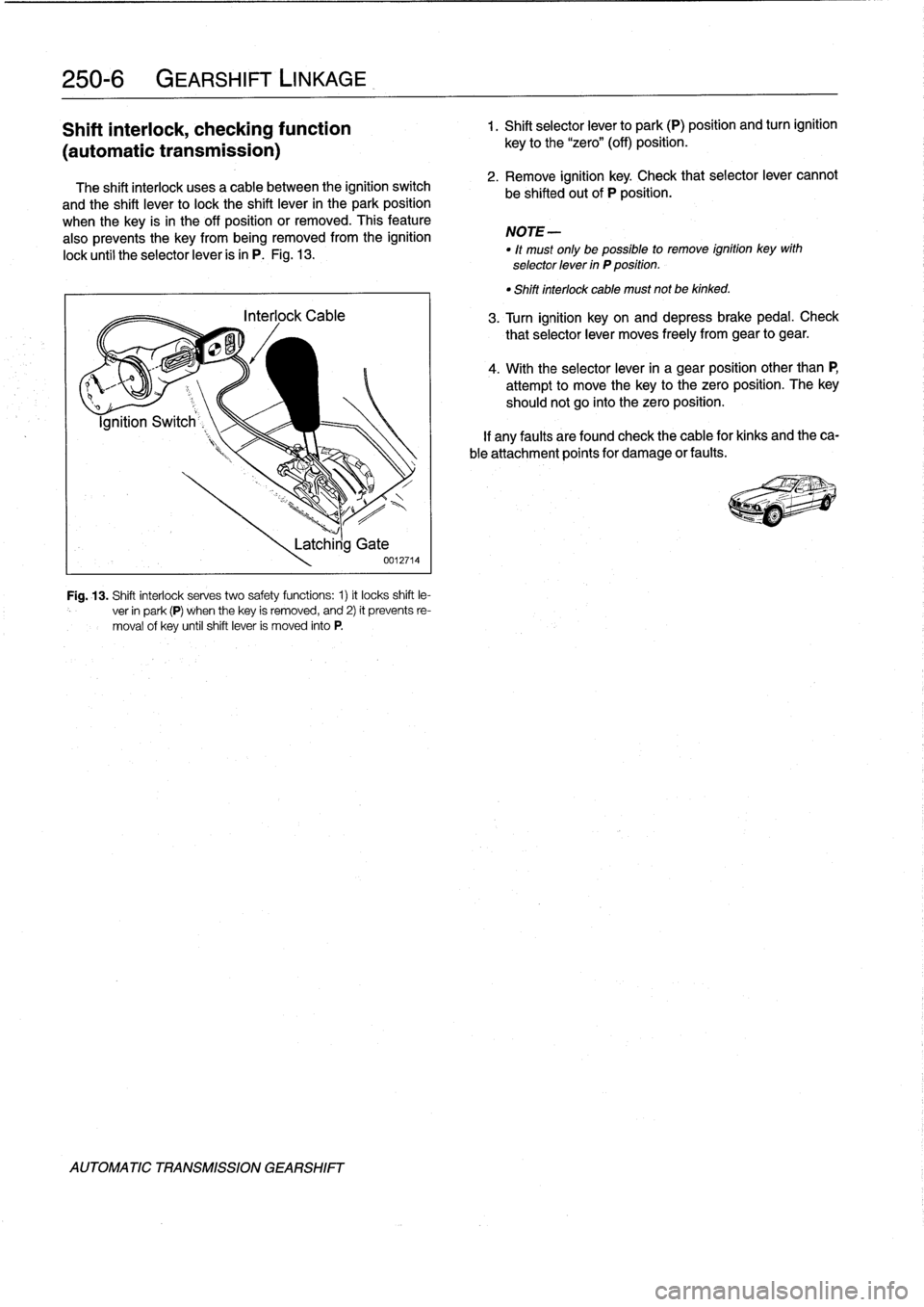
The
shift
interlock
usesa
cable
between
the
ignition
switch
and
the
shift
lever
to
lock
the
shift
lever
in
the
park
position
when
the
key
is
in
the
off
position
or
removed
.
This
feature
also
prevents
the
key
from
being
removed
from
the
ignition
lock
until
the
selectorlever
is
in
P
.
Fig
.
13
.
Fig
.
13
.
Shift
interlock
serves
two
safety
functions
:
1)
it
locks
shift
le-
ver
in
park
(P)
when
thekey
is
removed,
and
2)
it
prevents
re-
moval
of
key
untilshift
lever
is
moved
into
P
.
AUTOMATIC
TRANSMISSION
GEARSHIFT
Latchirig
Gate
0012714
key
to
the
"zero"
(off)
position
.
2
.
Remove
ignition
key
.
Check
that
selectorlever
cannot
be
shifted
out
of
P
position
.
NOTE-
"
lt
must
only
be
possible
to
remove
ignition
key
with
selector
lever
in
P
position
.
"
Shiftinterlock
cable
must
not
be
kinked
.
3
.
Turn
ignition
keyon
and
depressbrakepedal
.
Check
that
selectorlever
moves
freely
from
gear
to
gear
.
4
.
With
the
selectorlever
in
a
gear
position
other
than
P,
attempt
to
move
thekey
to
the
zero
position
.
The
key
shouldnot
go
into
the
zero
position
.
If
any
faults
arefound
check
the
cable
for
kinks
and
theca-
ble
attachment
points
for
damage
or
faults
.
Page 241 of 759
DRIVESHAFT
SERVICE
.
...
.
.
.
...
.
..
.
.
.260-3
Driveshaft,
aligning
...............
.
...
.
.
260-3
Driveshaft,
removing
..............
.
.
.
.
.
.
260-4
260
Driveshaft
DRIVESHAFT
260-1
GENERAL
.
.
.
.
.
.
.
.....
.
.
.
........
.
...
.
260-1
Driveshaft,
installing
.
....
.
..
.
............
260-4
Flex-disc,
replacing
.....
.
.
.
.............
260-5
TROUBLESHOOTING
..
.
.
.
...
.
.........
260-1
Center
bearing
assembly,
replacing
.
......
.260-6
Frontcentering
guide,
replacing
..
.
.......
.
260-7
TABLE
a
.
Driveshaft
Troubleshooting
.
.
...
......
.
....
..
.
.
260-2
GENERAL
NOTE-
For
rear
drive
axlerepair
information,
see330
Rear
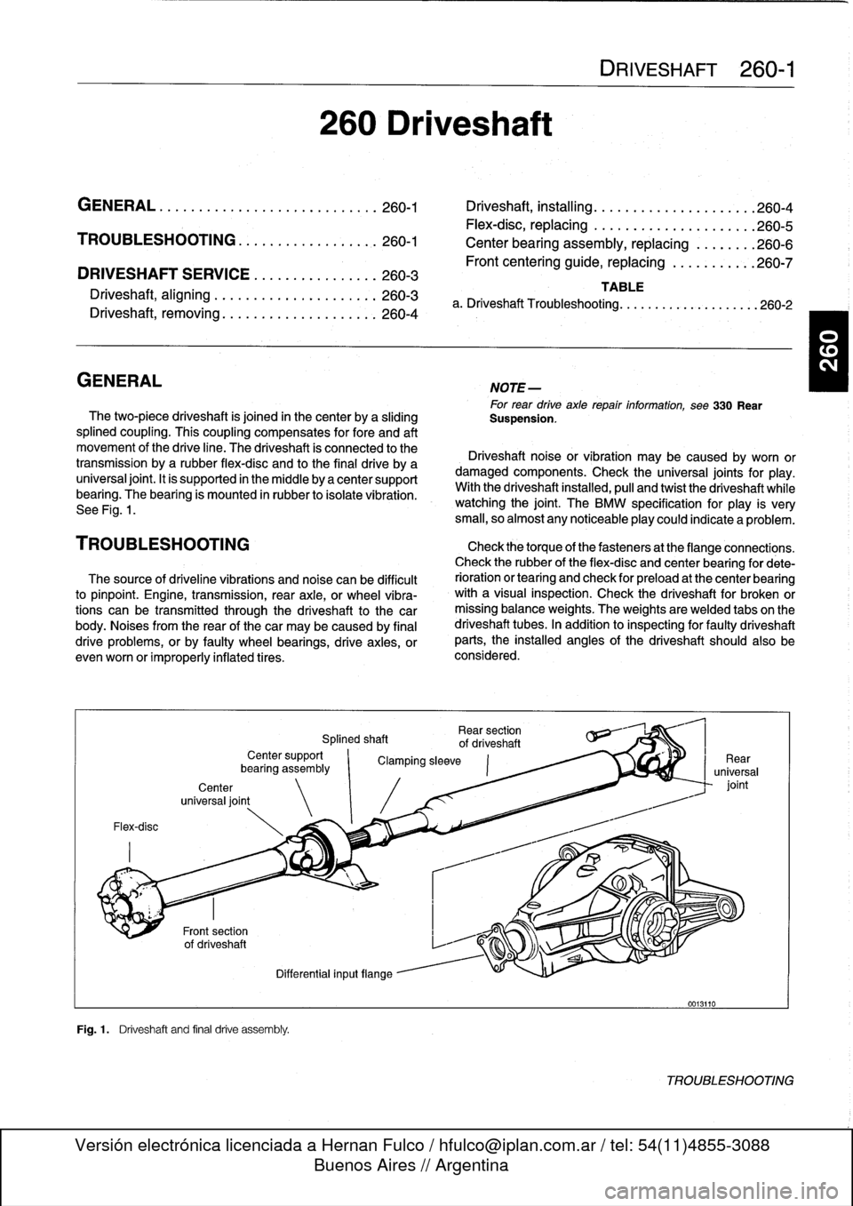
The
two-piece
driveshaft
is
joined
in
thecenter
by
a
sliding
Suspension
.
splined
coupling
.
This
coupling
compensates
for
fore
and
aft
movement
of
the
drive
line
.
The
driveshaft
ís
connected
to
the
Driveshaft
noise
or
vibration
may
be
caused
by
worn
or
transmission
bya
rubber
flex-disc
and
to
the
final
drive
by
a
damaged
components
.
Check
the
universal
joints
for
play
.
universal
joint
.
It
is
supported
in
the
micidle
by
a
center
support
With
the
driveshaft
installed,
pull
and
twist
the
driveshaft
while
bearing
.
The
bearing
is
mounted
in
rubber
to
isolate
vibration
.
watching
the
joint
.
The
BMW
specificationfor
play
is
very
See
Fig
.
1
.
small,
so
almost
any
noticeableplay
could
indicate
a
problem
.
TROU
BLESHOOTING
Check
thetorque
of
thefasteners
at
the
flange
connections
.
Check
therubber
of
the
flex-disc
and
center
bearing
for
dete
The
source
of
driveline
vibrations
and
noise
can
be
difficult
rioration
or
tearíng
and
check
for
preload
at
the
center
bearing
to
pinpoint
.
Engine,
transmission,
rear
axle,
or
wheel
vibra-
with
a
visual
inspection
.
Check
the
driveshaft
for
broken
or
tions
can
be
transmitted
through
the
driveshaft
to
the
car
missing
balance
weights
.
The
weights
are
welded
tabs
on
the
body
.
Noises
from
the
rear
of
thecar
may
be
caused
by
final
driveshaft
tubes
.
In
addition
to
inspecting
for
faulty
driveshaft
drive
problems,
orby
faulty
wheel
bearings,
drive
axies,
or
parts,
the
installed
angles
of
the
driveshaft
should
also
be
evenworn
or
improperly
inflatedtires
.
considered
.
Flex-disc
Center
universal
joint
Fig
.1
.
Driveshaft
and
final
drive
assembly
.
Rear
section
Splined
shaft
of
driveshaft
Center
support
`
Clamping
sleeve
bearíng
assembly
Differential
inputflange
0013110
TROUBLESHOOTING
Page 242 of 759
260-2
DRIVESHAFT
Further
inspection
requires
removal
of
the
driveshaft
.
Check
the
front
centering
guide
on
the
transmission
output
flange
for
damage
or
misalignment
.
Also
check
runoutatthe
transmission
outputflange
and
output
shaft,
and
at
the
final
drive
input
flange
.
Check
the
bolt
hole
bores
in
theflange
for
wear
and
elongation
.
Driveshaftflange
runout
(max
.
allowable)
"
Transmission
outputflange
axial
play
...
.
..
...
..
.
.......
0
.10
mm
(0
.004
in
.)
radial
play
.......
...
.
.
.......
0
.07
mm
(0
.003
in
.)
"
Final
driveinput
flange
radial
play
(measured
at
driveshaft
centering
lip)
..
......
0
.07
mm
(0
.003
in
.)
Spinthe
center
bearing
and
check
for
the
smooth
operation
without
play
.
Check
that
thesplines
of
the
sliding
coupling
move
freely
.
Clean
and
lubricate
the
splines
with
molybdenum
disulfide
grease
(Molykote
®
Longterm
2
or
equivalent)
.
Check
the
universal
joints
for
wear
or
binding
.
If
any
joint
isdif-
ficult
to
move
or
binds,
the
driveshaft
section
should
be
replaced
.
Table
a
.
Driveshaft
Troubleshooting
NOTE-
With
the
driveshaft
installed,
theactual
amount
that
the
universal
joints
pivot
is
limited
.
For
the
most
accurate
test,
check
universal
joints
in
their
normal
range
of
movement
.
If
inspection
revealsnothing
wrong
with
the
driveshaft,
it
may
need
to
be
rebalanced
.
This
can
be
done
by
a
speciality
driveshaft
repair
shop
.
Also,
check
the
alignment
ofthe
drive-
shaft
as
described
below
.
NOTE-
Minor
driveshaftvibrations
can
often
be
correctedsim-
ply
by
disconnecting
the
driveshaftat
the
finaldrive,
and
repositíoning
the
driveshaft
90°,
180°
or270°
inre-
lationto
the
final
drive
input
flange
.
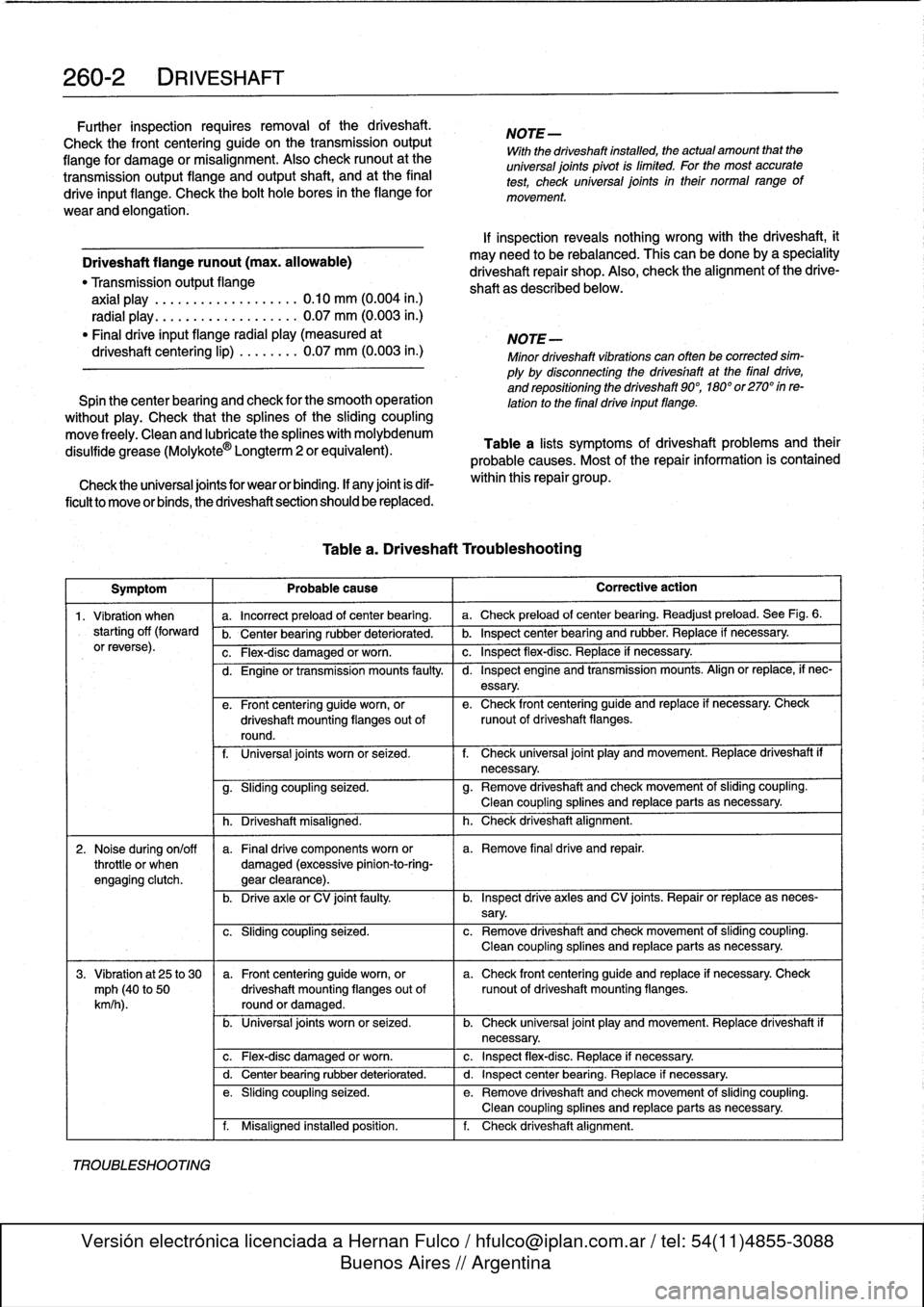
Table
a
lists
symptoms
of
driveshaft
problems
and
their
probable
causes
.
Most
of
the
repair
information
is
contained
within
this
repair
group
.
Symptom
Probable
cause
Corrective
action
1
.
Vibration
when
a
.
Incorrect
preload
of
center
bearing
.
a
.
Check
preload
of
center
bearing
.
Readjust
preload
.
See
Fig
.
6
.
starting
off
(forward
b
.
Center
bearing
rubber
deteriorated
.
b
.
Inspect
center
bearing
and
rubber
.
Replace
if
necessary
.
orreverse)
.
c
.
Flex-disc
damaged
or
worn
.
c
.
Inspect
flex-disc
.
Replace
if
necessary
.
TROUBLESHOOTING
d
.
Engine
or
transmission
mounts
faulty
.
I
d
.
Inspect
engine
and
transmission
mounts
.
Align
or
replace,
if
nec-
essary
.
e
.
Front
centering
guide
worn,
or
e
.
Check
front
centering
guide
and
replace
if
necessary
.
Check
driveshaft
mounting
flanges
out
of
runout
of
driveshaft
flanges
.
round
.
f
.
Universal
joints
worn
or
seized
.
f
.
Check
universal
joint
play
and
movement
.
Replace
driveshaft
if
necessary
.
g
.
Sliding
coupling
seized
.
g
.
Remove
driveshaft
and
check
movement
of
sliding
coupling
.
Clean
coupling
splines
and
replace
parts
asnecessary
.
h
.
Driveshaft
misaligned
.
h
.
Check
driveshaft
alignment
.
2
.
Noise
during
on/off
a
.
Finaldrive
components
worn
or
a
.
Remove
final
drive
and
repair
.
throttle
or
when
damaged
(excessive
pinion-to-ring-
engagíng
clutch
.
gear
clearance)
.
b
.
Drive
axleor
CV
joint
faulty
.
b
.
Inspect
drive
axles
and
CV
joints
.
Repair
or
replace
as
neces-
sary
.
c
.
Sliding
coupling
seized
.
c
.
Remove
driveshaft
and
check
movement
of
sliding
coupling
.
Clean
coupling
splines
and
replace
parts
as
necessary
.
3
.
Vibration
at
25
to
30
a
.
Front
centering
guideworn,
or
a
.
Check
front
centering
guide
and
replace
if
necessary
.
Check
mph
(40
to
50
driveshaft
mounting
flanges
out
of
runout
of
driveshaft
mounting
flanges
.
km/h
).
round
or
damaged
.
b
.
Universal
joints
worn
or
seized
.
b
.
Check
universal
joint
play
and
movement
.
Replace
driveshaft
if
necessary
.
c
.
Flex-disc
damaged
or
worn
.
c
.
Inspect
flex-disc
.
Replace
if
necessary
.
d
.
Center
bearing
rubber
deteriorated
.
d
.
Inspect
center
bearing
.
Replace
if
necessary
.
e
.
Sliding
coupling
seized
.
e
.
Remove
driveshaft
and
check
movement
of
sliding
coupling
.
Clean
coupling
splines
and
replace
parts
asnecessary
.
f
.
Misaligned
installed
position
.
f
.
Check
driveshaft
alignment
.
Page 243 of 759
Symptom
1
Probable
cause
4
.
Vibration,
audible
a
.
Front
centering
guide
worn,
or
a
.
Check
front
centering
guide
and
replace
if
necessary
.
Check
rumble
over35
mph
driveshaft
mounting
flanges
out
of
runout
of
driveshaft
mounting
flanges
.
(60
km/h)
.
round
or
damaged
.
b
.
Mounting
flange
bolts
loose
or
holes
b
.
Remove
driveshaft
and
check
transmissionoutput
flange
and
worn
.
final
drive
input
flange
.
Replace
if
necessary
.
c
.
Driveshaft
unbalanced
.
c
.
Check
driveshaft
for
loose
or
missing
balance
weights
.
Have
driveshaft
rebalanced
or
replace
if
necessary
.
DRIVESHAFT
SERVICE
Driveshaft,
aligning
d
.
Universal
joints
worn
or
seized
.
d
.
Check
universal
joint
play
and
movement
.
Replace
driveshaft
if
necessary
.
e
.
Sliding
coupling
seized
.
e
.
Remove
driveshaft
and
check
movement
of
sliding
coupling
.
1
Clean
coupling
splines
or
replace
parts
asnecessary
.
f
.
Incorrect
preload
of
center
bearing
.
f
.
Check
preload
of
center
bearing
.
Readjust
if
necessary
.
g
.
Center
bearing
faulty
.
g
.
Replace
center
bearing
.
h
.
Final
drive
rubber
mount
faulty
h
.
Inspect
final
drive
rubber
mount
and
replace
if
necessary
.i.
Driveshaft
misaligned
.
i.
Check
driveshaft
alignment
.
Repair
kits
for
the
universal
joints
are
not
available,
and
it
is
not
common
practice
to
repair
the
universal
joints
on
BMW
driveshafts
.
Worn
or
damaged
universal
joints
usually
require
replacement
of
that
section
of
the
driveshaft
.
The
driveshaft
is
balanced
to
cose
tolerances
.
Whenever
it
is
to
be
removed
or
disassembied,
the
mounting
flanges
and
driveshaft
sections
should
bemarked
with
paint
or
a
punch
before
proceeding
with
work
.
This
will
ensure
that
the
drive-
shaft
can
be
reassembled
or
installed
in
exactlythe
same
ori-
entation
.
Universal
joint
play
"
Maximum
allowable
...........
0.15
mm
(0.006
in
.)
The
alignment
of
the
driveshaft
does
not
normally
need
to
be
checked
unless
the
engine/transmission
orthe
final
drive
havebeen
removed
and
installed
.
If,
however,
all
other
parts
of
the
driveshaft
havebeen
inspected
and
found
to
be
okay,
butthere
is
still
noise
or
vibration,
driveshaft
alignment
should
be
checked
.
There
aretwo
important
driveshaft
alignment
checks
.
The
first
is
to
make
sure
that
the
driveshaft
runs
straight
from
the
transmission
to
the
final
drive
;
without
any
variation
from
side-
to-side
caused
by
misalignment
ofthe
engine/transmission
in
its
mounts
.
Make
a
basic
check
by
sighting
along
the
drive-
shaft
from
back
lo
front
.
Any
misalignmentshould
be
apparent
from
the
center
bearingforward
.
To
adjustthe
side-to-side
alignment,
loosen
the
transmission
or
engine
mounts
to
repo-
sition
them,
then
retighten
the
mounts
:
The
driveshaft
should
be
exactly
centered
in
the
driveshaft
tunnel
.
See
Fig
.
2
.
Table
a
.
Driveshaft
Troubleshooting
(continued)
DRIVESHAFT
260-3
Corrective
action
b
:izó
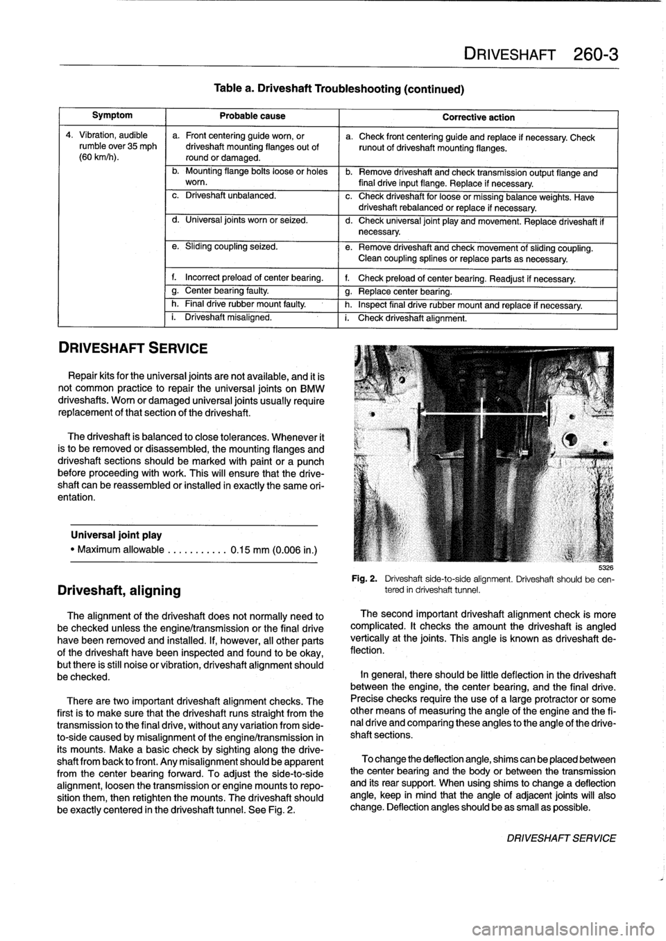
Fig
.
2
.
Driveshaft
side-to-side
alignment
.
Driveshaft
should
be
cen-
tered
in
driveshaft
tunnel
.
The
second
important
driveshaft
alignment
check
is
more
complicated
.
It
checks
the
amount
the
driveshaft
is
angled
vertically
at
the
joints
.
This
angle
is
known
as
driveshaft
de-
flection
.
In
general,
there
should
be
little
deflection
in
the
driveshaft
between
the
engine,
thecenter
bearing,
and
the
final
drive
.
Precise
checks
require
theuse
of
a
large
protractor
or
some
other
means
of
measuring
the
angle
of
the
engine
and
the
fi-
nal
drive
and
comparing
these
angles
to
the
angle
of
the
drive-
shaft
sections
.
To
change
the
deflection
angle,
shims
can
be
placed
between
the
center
bearing
and
the
body
or
between
the
transmission
and
íts
rear
support
.
When
using
shims
to
change
a
deflection
angle,
keep
in
mind
that
the
angle
of
adjacent
joints
will
also
change
.
Deflection
anglesshould
beas
small
as
possible
.
DRIVESHAFTSERVICE
Page 256 of 759
300-8
SUSPENSION,
STEERING
AND
BRAKES-GENERAL
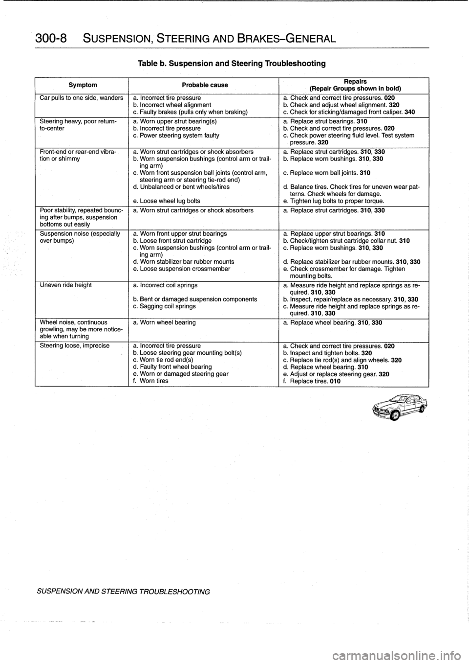
Tableb
.
Suspension
and
Steering
Troubleshooting
Symptom
1
Probable
cause
Repairs
(Repair
Groups
shown
in
bold)
Car
pulís
to
one
side,
wanders
a
.
Incorrect
tire
pressure
a
.
Check
and
correct
tire
pressures
.
020
b
.
Incorrect
wheel
alignment
b
.
Check
and
adjust
wheel
alignment
.
320
c
.
Faulty
brakes
(pulls
only
when
braking)
I
c
.
Check
for
sticking/damaged
front
caliper
.
340
Steering
heavy,
poor
return-
a
.
Worn
upper
strut
bearing(s)
a
.
Replace
strut
bearings
.
310
to-center
b
.
Incorrect
tire
pressure
b
.
Check
and
correct
tire
pressures
.
020
c
.
Power
steering
system
faulty
c
.
Check
power
steering
fluid
level
.
Test
system
pressure
.
320
Front-end
or
rear-end
vibra-
a
.
Worn
strut
cartridgesor
shock
absorbers
a
.
Replace
strut
cartridges
.
310,
330
tion
or
shimmy
b
.
Worn
suspension
bushings
(control
arm
or
trail-
b
.
Replace
worn
bushings
.
310,
330
ing
arm)
c
.
Worn
front
suspension
ball
joints
(control
arm,
c
.
Replace
worn
ball
joints
.
310
steering
arm
orsteering
tie-rod
end)d
.
Unbalanced
or
bent
wheels/tires
d
.
Balance
tires
.
Check
tiresfor
uneven
wear
pat-
terns
.
Check
wheels
for
damage
.
e
.
Loose
wheel
lug
boits
e
.
Tighten
lug
boits
to
proper
torque
.
Poor
stability,
repeated
bounc-
I
a
.
Worn
strut
cartridgesor
shock
absorbers
I
a
.
Replace
strut
cartridges
.
310,
330
ing
after
bumps,
suspension
bottoms
outeasily
Suspension
noise
(especially
a
.
Worn
front
upper
strut
bearings
a
.
Replaceupper
strut
bearings
.
310
over
bumps)
b
.
Loose
front
strut
cartridge
b
.
Check/tighten
strut
cartridge
collar
nut
.
310
c
.
Worn
suspensionbushings
(control
arm
or
trail-
c
.
Replace
worn
bushings
.
310,
330
ing
arm)d
.
Worn
stabilizer
bar
rubber
mounts
d
.
Replace
stabilizer
bar
rubber
mounts
.
310,
330
e
.
Loose
suspension
crossmember
e
.
Check
crossmember
for
damage
.
Tighten
mounting
boits
.
Uneven
ride
height
a
.
Incorrect
coil
springs
a
.
Measure
ride
height
and
replacesprings
as
re-
quired
.
310,
330
b
.
Bent
or
damaged
suspension
components
b
.
Inspect,
repair/replace
asnecessary
.
310,
330
c
.
Sagging
coil
springs
c
.
Measure
ride
height
and
replace
springs
as
re-
quired
.
310,
330
Wheel
noise,
continuous
I
a
.
Worn
wheel
bearing
I
a
.
Replacewheel
bearing
.
310,
330
growling,
may
be
more
notíce-
able
when
turning
Steering
loose,
imprecise
a
.
Incorrect
tire
pressure
a
.
Check
and
correct
tire
pressures
.
020
-
b
.
Loose
steering
gearmounting
bolt(s)
b
.
Inspect
and
tighten
boits
.
320
c
.
Worn
tie
rodend(s)
c
.
Replace
tie
rod(s)
and
align
wheels
.
320
d
.
Faulty
front
wheel
bearing
d
.
Replace
wheel
bearing
.
310
e
.
Worn
or
damaged
steering
gear
e
.
Adjust
or
replace
steering
gear
.
320
f
.
Worn
tires
f
.
Replace
tires
.
010
SUSPENSION
AND
STEERING
TROUBLESHOOTING
Page 287 of 759
GENERAL
......
.
.
.
.
.
.
.
.....
.
.
.
.
.
.
.
.
.
.
331-1
Final
Drive
Oil
Seals
.
.
...
.
.
.
.......
.
.
.
.
.
331-1
Finaldrive
flange
oil
sea¡,
replacing
....
.
.
.
..
331-2
FINAL
DRIVE
SERVICE
.
.....
.
.
.
.
.
.
.
.
.
.
331-1
Finaldrive
inputshaft
oil
seal,
replacing
.
.
.
.
.
331-3
Final
drive
oí¡,
draining
and
filling
.
.
.
.
.
.
.
.
.
.
331-1
Finaldrive
unit,
removíng
and
installing
.
.
.
.
.
.
331-3
GENERAL
This
repa¡r
group
covers
repair
operations
that
do
not
re-
quire
complicated
disassembly
of
the
final
drive
.
Internal
re-
pairs
and
final
drive
disassembly
are
not
covered
in
this
manual
.
FINAL
DRIVE
SERVICE
Al¡
final
drive
work
requires
some
method
of
raising
thecar
and
supporting
it
securely
while
the
work
is
performed
.
Jack
stands
and
a
floor
jack
can
easily
be
used,
but
use
extreme
caution
when
working
beneath
the
car
.
See010
Fundamen-
tais
for
the
Do-It-Yourself
Owner
.
NOTE-
Removal
of
final
drive
carrier
is
covered
in
330
Rear
Suspension
.
Final
drive
oil,
draining
and
filling
1
.
Drive
car
to
warm
final
drive
fluid
.
2
.
Raise
car
and
support
safely
.
WARNING
-
Make
sure
that
thecar
is
firmly
supported
on
jack
standsdesigned
for
the
purpose
.
Place
the
jack
standsbeneatha
structural
chassis
point
.
Do
not
place
jack
stands
under
suspension
parts
.
5
.
Fill
final
drive
with
appropriate
type
and
quantity
of
lu-
bricant
.
Insta¡¡
and
tighten
fill
plug
.
331
Final
Drive
0
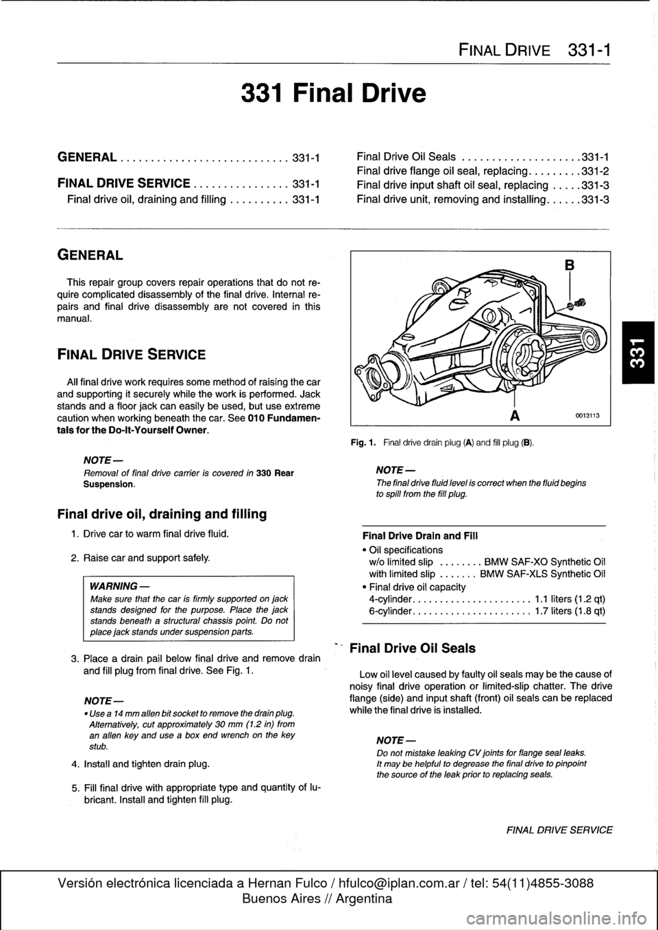
Fig
.
1
.
Final
drivedrain
plug
(A)
and
fill
plug
(B)
.
D
NOTE-
The
final
drive
fluid
level
is
correct
when
the
fluid
begins
to
spill
from
the
fill
plug
.
Final
Drive
Oil
Seals
FINAL
DRIVE
331-1
0013113
Final
DriveDrain
and
Fill
"
Oil
specifications
w/o
limited
slip
.
.......
BMW
SAF-XO
Synthetic
Oil
with
limited
slip
.
......
BMW
SAF-XIS
Synthetic
Oil
"
Final
drive
oil
capacity
4-cylinder
.
.
.
...
................
1
.1
liters
(1
.2
qt)
6-cylinder
.
.
.
...
................
1
.7liters(1.8
qt)
3
.
Place
a
drain
pail
below
final
drive
andremove
drain
and
fill
plugfrom
final
drive
.
See
Fig
.
1
.
Low
oil
level
caused
by
faulty
oil
seals
may
be
the
cause
of
noisy
final
drive
operation
or
limited-slip
chatter
.
The
drive
NOTE-
flange
(side)
and
inputshaft
(front)
oil
seals
can
be
replaced
"
Use
a14
mm
alíen
bit
socket
to
remove
the
drain
plug
.
while
the
final
drive
is
installed
.
Alternatively,
cut
approximately
30
mm
(1
.2
in)
from
an
alíen
key
and
usea
box
end
wrenchon
the
key
NOTE-
stub
.
Do
not
mistake
leaking
CV
joints
for
flangeseal
leaks
.
4
.
Install
and
tighten
drain
plug
.
It
may
be
helpful
to
degrease
the
final
drive
to
pinpoint
the
source
of
the
leak
prior
to
replacing
seals
.
FINAL
DRIVE
SERVICE
Page 289 of 759
Final
driveinputshaft
oil
sea¡,
replacing
1
.
Raise
car
and
support
safely
.
2
.
Drain
final
drive
oil
as
described
earlier
.
3
.
Remove
driveshaft
from
final
drive
inputshaft
flange
.
See
260
Driveshaft
.
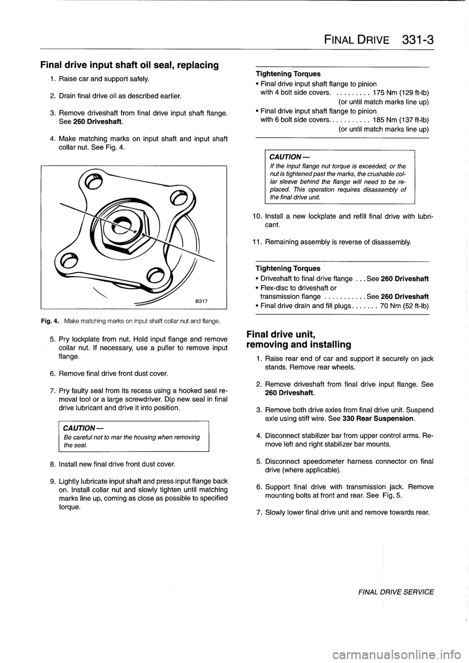
4
.
Make
matching
marks
on
input
shaft
and
inputshaft
collar
nut
.
See
Fig
.
4
.
Fig
.
4
.
Make
matching
marks
on
input
shaft
collar
nut
and
flange
.
5
.
Pry
lockplate
from
nut
.
Hold
input
flange
andremove
collar
nut
.
If
necessary,
usea
pullerto
remove
input
flange
.
6
.
Remove
final
drive
front
dust
cover
.
8
.
Install
new
final
drivefront
dust
cover
.
9
.
Lightly
lubricate
inputshaft
and
press
input
flange
back
on
.
Insta¡¡
collar
nut
and
slowly
tighten
until
matching
marks
line
up,
coming
as
close
aspossible
to
specified
torque
.
Tightening
Torques
"
Final
driveinputshaft
flange
to
pinion
with
4
bolt
side
covers
.
.........
175
Nm
(129
ft-Ib)
(or
until
match
marks
line
up)
"
Finaldriveinputshaft
flange
to
pinion
with
6
bolt
side
covers
...........
185
Nm
(137
ft-Ib)
(or
until
match
marks
line
up)
CA
UTION-
If
the
input
flange
nuttorque
is
exceeded,
or
the
nut
is
tightened
past
the
marks,
the
crushable
col-
lar
sleeve
behind
theflange
will
need
to
be
re-
placed
.
This
operation
requires
disassembly
of
the
final
drive
unit
.
10
.
Install
a
new
lockplate
and
refill
final
drive
with
lubri-
cant
.
11
.
Remaining
assembly
is
reverse
of
disassembly
.
Tightening
Torques
"
Driveshaftto
final
dríve
flange
...
See260
Driveshaft
"
Flex-disc
to
driveshaft
or
transmission
flange
...........
See260
Driveshaft
"
Finaldrivedrain
and
fill
plugs
...
.
..
.
70
Nm
(52
ft-Ib)
Final
drive
unit,
removing
and
installing
FINAL
DRIVE
331-
3
1
.
Raise
rear
end
of
car
and
support
it
securely
on
jack
stands
.
Remove
rear
wheels
.
2
.
Remove
driveshaft
from
final
drive
input
flange
.
See
7
.
Pry
faulty
sea¡
from
its
recess
using
a
hooked
sea¡
re-
260
Driveshaft
.
moval
toolor
a
large
screwdriver
.
Dip
new
sea¡
in
final
drive
lubricant
and
drive
it
into
position
.
3
.
Remove
both
drive
axles
from
final
drive
unit
.
Suspend
axle
using
stiff
wire
.
See
330
Rear
Suspension
.
CAUTION
-
ee
careful
not
to
mar
the
housing
when
removing
4
.
Disconnect
stabilizer
bar
from
upper
control
arms
.
Re-
the
seas
.
move
left
and
rightstabilizer
bar
mounts
.
5
.
Disconnect
speedometer
harness
connector
on
final
drive
(where
applicable)
.
6
.
Support
final
drive
with
transmission
jack
.
Remove
mounting
bolts
atfront
and
rear
.
See
Fig
.
5
.
7
.
Slowly
lower
final
drive
unit
and
remove
towards
rear
.
FINAL
DRIVE
SERVICE
Page 291 of 759
Brake
rotor,
removing
and
installing
.
.
.
.
.
.
.
.
340-7
MASTER
CYLINDER
............
.
.
.
.
.
.
.340-7
Master
cylinder,
removing
and
installing
.
...
.
340-7
GENERAL
TROUBLESHOOTING
WARNING
-
"
Although
semi-metallic
and
metallic
Brake
friction
materials
in
Brake
pads
or
shoes
no
longer
con-
tain
asbestos,
they
produce
dangerous
dust
.
"
Brake
fluid
is
poisonous,
highly
corrosive
and
dangerous
to
the
environment
Wear
safety
glasses
and
rubber
gloves
when
working
with
Brake
fluid
.
Do
not
siphonBrake
fluid
with
your
mouth
.
Immediately
clean
away
any
fluid
spilled
on
painted
surfaces
and
wash
with
water,
asBrake
fluid
will
remove
paint
.
"
Always
use
new
Brake
fluid
froma
fresh,
un-
opened
container
.
Brake
fluid
will
absorb
mois-
ture
from
the
air
.
This
canlead
to
corrosion
problems
in
the
brakingsystem,
and
will
also
low-
er
the
Brake
fluid's
boiling
point
.
Dispose
of
Brake
fluid
properly
.
"
Do
notreuse
self-locking
nuts,bolts
or
fasteners
.
They
are
designed
to
be
used
only
once
and
may
failif
reused
.
Always
replace
them
with
new
self-
locking
fasteners
.
BMW
E36
models
areequipped
with
vacuum
power-assist-
ed
four-wheel
disc
brakes
with
an
integral
Antilock
Brake
Sys-
tem
(ABS)
.
Single-pistoncalipers
act
on
solid
or
vented
front
rotors
and
solid
rear
rotors
.
A
brake
pad
wear
sensor
for
each
axle
indicates
when
brake
padsneed
replacement
.
The
dual
drum-type
parking
brakesystem
is
integrated
with
the
rear
brake
rotors
.
NOTE-
M3
models
havevented
directional
Brake
rotors
on
the
rearaxle
as
well
ason
the
front
.
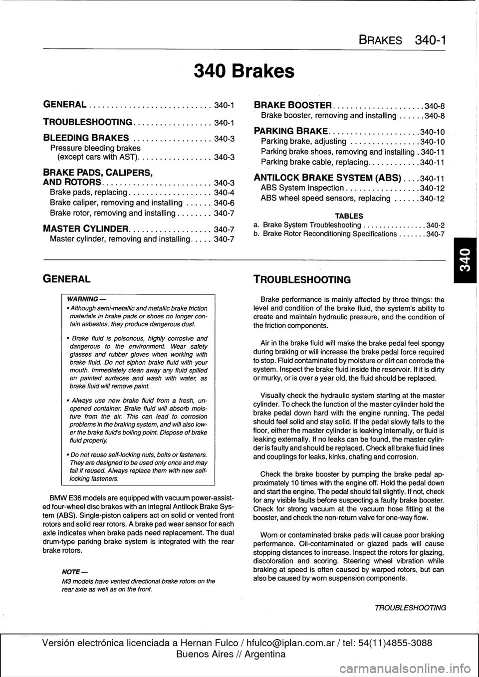
340
Brakes
BRAKES
340-1
GENERAL
.
.
.
.
.
.
.........
.
.
.
..........
340-1
BRAKE
BOOSTER
.........
.
.
.
.
.
...
.
.
.
.
340-8
TROUBLESHOOTING
.......
.
......
.
...
340-1
Brake
booster,
removing
and
installing
....
.
.
340-8
PARKING
BRAKE
.
.....
.
...
.
.
.
.....
.
.
.
340-10
BLEEDING
BRAKES
.
.
.
.
.
.
.
.
..........
340-3
Parking
brake,adjusting
.
.
.
.
.
.
.
.
.
.
.....
.
340-10
Pressure
bleeding
brakes
Parking
brake
shoes,
removing
and
installing
.
340-11(except
cars
with
AST)
.
.
.
.
.
.
.
.
.
...
.
.
.
.
.340-3
Parking
Brake
cable,
replacing
.
.
.
.
.
.
.
.
.
.
.
.
340-11
BRAKE
PADS,
CALIPERS,
ANTILOCK
BRAKE
SYSTEM
(ABS)
.
.
.
.340-11
AND
ROTORS
..........
.
.......
.
.
.
.
.
.
.
340-3
ABS
System
Inspection
.
...
.
.......
.
.
.
..
340-12
Brake
pads,
replacing
............
.
.
.
.
.
.
.
340-4
ABS
wheel
speed
sensors,
replacing
.
.
.
.
..
340-12
Brake
caliper,
removing
and
installing
.
..
..
.
340-6
TABLES
a
.
Brake
System
Troubleshooting
.....
...
.
.
.....
.340-2
b
.
Brake
Rotor
Reconditioning
Specifications
.
.....
.340-7
Brakeperformance
is
mainly
affected
by
three
things
:
the
leve¡
and
condition
of
the
brake
fluid,
the
system's
abilíty
to
create
and
maintain
hydraulic
pressure,
and
the
condition
of
the
friction
components
.
Air
in
the
Brake
fluid
will
make
the
Brake
pedal
feel
spongy
during
braking
or
will
increase
the
Brake
pedalforce
required
to
stop
.
Fluid
contaminated
by
moisture
or
dirt
can
corrode
the
system
.
Inspect
the
Brake
fluid
inside
the
reservoir
.
Ifit
is
dirty
or
murky,
or
is
over
a
year
old,
the
fluid
should
be
replaced
.
Visually
check
the
hydraulic
system
startingat
the
master
cylinder
.
To
check
the
function
of
the
master
cylinder
hold
the
brake
pedal
down
hard
with
the
engine
running
.
The
pedal
should
feelsolid
and
stay
solid
.
If
the
pedal
slowly
falls
to
the
floor,
either
the
master
cylinder
is
leaking
internally,
or
fluid
is
leaking
externally
.
If
no
leaks
canbe
found,
the
master
cylin-
der
is
faulty
and
should
be
replaced
.
Check
all
Brake
fluid
lines
and
couplings
for
leaks,
kinks,
chafing
and
corrosion
.
Check
the
Brake
booster
by
pumping
the
Brake
pedal
ap-
proximately
10
times
with
the
engine
off
.
Hold
the
pedal
down
and
start
the
engine
.
The
pedal
should
fa¡¡
slightly
.
If
not,
check
for
any
visiblefaults
before
suspecting
a
faulty
brake
booster
.
Check
for
strong
vacuum
at
the
vacuum
hose
fitting
at
the
booster,
and
check
the
non-retum
valve
for
one-way
flow
.
Worn
or
contaminated
brake
pads
will
cause
poor
braking
performance
.
Oil-contaminated
or
glazed
pads
will
cause
stopping
distances
to
increase
.
Inspect
the
rotors
for
glazing,
discoloration
and
scoring
.
Steering
wheel
vibration
while
braking
at
speed
is
often
caused
by
warped
rotors,
but
can
also
be
caused
byworn
suspension
components
.
TROUBLESHOOTING
Page 292 of 759
340-2
BRAKES
When
troubleshooting,
keep
in
mind
that
tire
inflation,
wear
and
temperature
can
affect
braking
and
suspension
.
See310
Front
Suspension
for
more
information
on
front
suspension
parts
inspection
.
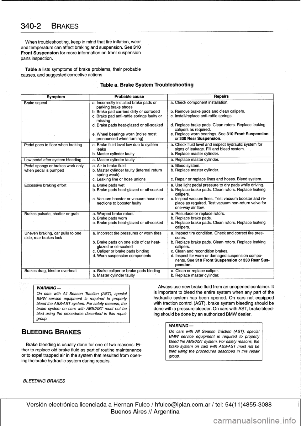
Table
a
lists
symptoms
of
brake
problems,
their
probable
causes,
and
suggested
corrective
actions
.
Table
a
.
Brake
System
Troubleshooting
Symptom
1
Probable
cause
1
Repairs
Brake
squeal
a
.
Incorrectly
installed
brake
pads
or
a
.
Check
component
installation
.
parking
brake
shoes
b
.
Brakepad
carriers
dirty
or
corroded
b
.
Remove
brake
pads
and
clean
calipers
.
c
.
Brake
pad
anti-rattle
springs
faulty
or
c
.
Install/replace
anti-rattle
springs
.
missing
d
.
Brakepads
heat-glazed
or
oil-soaked
d
.
Replace
brake
pads
.
Clean
rotors
.
Replace
leaking
calipers
as
required
.
e
.
Wheel
bearings
worn
(noise
most
e
.
Replace
worn
bearings
.
See310
Front
Suspension
pronounced
when
turning)
or
330
Rear
Suspension
.
Pedal
goes
to
f
loor
when
braking
a
.
Brake
fluid
leve¡
low
due
to
system
a
.
Check
fluidlevel
and
inspect
hydraulic
system
for
leaks
signs
of
leakage
.
Fill
and
bleed
system
.
b
.
Master
cylinder
faulty
I
b
.
Replacemaster
cylinder
.
Low
pedal
after
system
bleeding
1
a
.
Master
cylinder
faulty
1
a
.
Replace
master
cylinder
.
Pedal
spongy
or
brakes
work
only
a
.
Air
in
brake
fluid
a
.
Bleedsystem
.
when
pedal
is
pumped
b
.
Master
cylinder
faulty
(interna¡
return
b
.
Replacemaster
cylinder
.
spring
weak)
c
.
Leaking
line
or
hose
unions
c
.
Repair
or
replace
lines
and
hoses
.
Bleed
system
.
Excessive
braking
effort
a
.
Brake
pads
wet
a
.
Use
light
pedal
pressure
to
dry
pads
while
driving
.
b
.
Brake
pads
heat-glazed
oroil-soaked
b
.
Replace
brake
pads
.
Clean
rotors
.
Replace
leaking
calipers
.
c
.
Vacuum
booster
or
vacuum
hose
con-
c
.
Inspect
vacuum
lines
.
Test
vacuum
booster
and
re
nections
to
booster
faulty
place
as
required
.
Test
vacuum
non-return
valve
for
one-way
air
flow
.
Brakes
pulsate,
chatter
or
grab
a
.
Warped
brake
rotors
a
.
Resurface
or
replace
rotors
.
b
.
Brake
padsworn
b
.
Replace
brake
pads
.
c
.
Brake
pads
heat-glazed
or
oil-soaked
c
.
Replace
brake
pads
.
Clean
rotors
.
Replace
leaking
calipers
.
Uneven
braking,
car
pulís
to
one
a
.
Incorrect
tire
pressures
or
worn
tires
a
.
Inspect
tire
condition
.
Check
and
correct
tire
pres-
side,
rear
brakes
lock
sures
.
b
.
Brake
pads
on
one
side
of
car
heat-
b
.
Replace
brake
pads
.
Clean
rotors
.
Replace
leaking
glazed
or
oil-soaked
calipers
.
c
.
Caliper
or
brake
pads
binding
c
.
Clean
and
recondition
brakes
.
d
.
Worn
suspension
components
d
.
Inspect
for
worn
or
damaged
suspension
compo-
nents
.
See
310
Front
Suspension
or
330
Rear
Sus-
pension
.
Brakes
drag,
bind
or
overheat
a
.
Brake
caliper
or
brake
pads
binding
a
.
Clean
or
replace
caliper
.(
b
.
Master
cylinder
faulty
b
.
Replacemaster
cylinder
.
WARNING
-
On
cars
with
All
Season
Traction
(AST),
special
BMW
service
equipment
is
required
to
properly
bleed
the
ABS/AST
system
.
For
safety
reasons,
the
brake
system
on
carswith
ABS/AST
must
not
be
bled
using
the
procedures
described
inthis
repair
group
.
BLEEDING
BRAKES
Brake
bleeding
is
usually
done
for
one
of
two
reasons
:
Ei-
ther
to
replace
oíd
brake
fluid
as
part
of
routine
maintenance
or
to
expel
trapped
air
in
the
system
that
resulted
from
open-
ingthe
brake
hydraulic
system
during
repairs
.
BLEEDING
BRAKES
Alwaysuse
new
brake
fluid
from
an
unopened
container
.It
is
important
to
bleed
the
entire
system
when
any
part
of
the
hydraulic
system
has
been
opened
.
On
cars
not
equipped
with
traction
control
(AST),
brake
system
bleeding
should
be
done
with
a
pressure
bleeder
.
On
cars
with
AST,
brake
bleed-
ing
should
be
done
by
an
authorized
BMW
dealer
.
WARNING
-
On
cars
with
All
Season
Traction
(AST),
special
BMW
service
equipment
is
requíred
to
properly
bleed
the
ABS/AST
system
.
For
safetyreasons,
the
brake
system
on
carswith
ABS/AST
must
not
be
bled
using
the
procedures
described
inthís
repair
group
.
Page 295 of 759
6
.
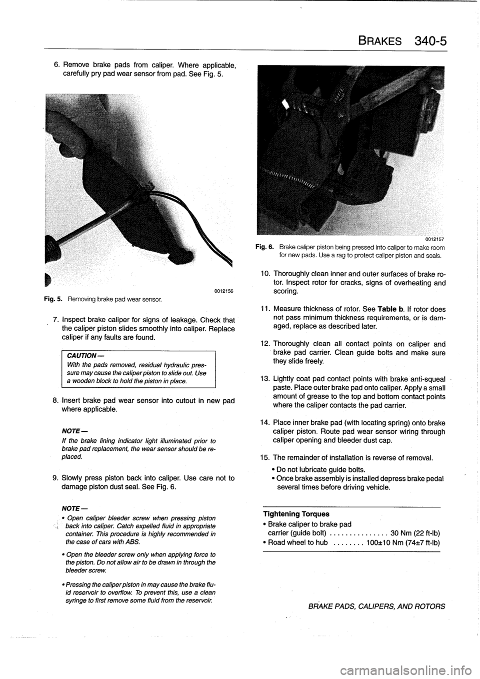
Remove
brake
pads
from
caliper
.
Where
applicable,
carefully
pry
pad
wear
sensor
from
pad
.
See
Fig
.
5
.
Fig
.
5
.
Removing
brake
pad
wear
sensor
.
7
.
Inspect
brake
caliper
for
signs
of
leakage
.
Check
that
the
caliper
piston
slides
smoothly
into
caliper
.
Replace
caliper
if
any
faults
are
found
.
CAUTION-
With
the
pads
removed,
residual
hydreulic
pres-
sure
may
cause
the
caliper
piston
to
slide
out
.
Use
a
wooden
block
to
hold
the
piston
in
place
.
8
.
fnsert
brake
pad
wear
sensor
into
cutout
in
new
pad
where
applicable
.
14
.
Place
inner
brake
pad
(with
locating
spring)
ontobrake
NOTE-
caliper
piston
.
Route
pad
wear
sensor
wiring
through
lf
the
brake
lining
indicator
light
illuminated
prior
to
caliper
opening
and
bleeder
dust
cap
.
brake
pad
replacement,
the
wear
sensor
should
be
re-
placed
.
15
.
The
remainder
of
installation
is
reverse
of
removal
.
"
Do
not
lubricate
guide
boits
.
9
.
Slowly
press
piston
back
into
caliper
.
Use
cace
not
to
"
Once
brake
assembly
is
installed
depress
brakepedal
damage
piston
dust
sea¡
.
See
Fig
.
6
.
severa¡
times
before
driving
vehicle
.
NOTE-
"
Open
caliper
bleeder
screw
when
pressing
piston
Tightening
Torques
back
into
caliper
.
Catch
expelled
fluidin
appropriate
"
Brake
caliper
to
brake
pad
container
.
This
procedure
is
highly
recommended
in
carrier
(guide
bolt)
..........
...
.
.
30
Nm
(22
ft-Ib)
the
case
of
cars
with
ABS
.
"
Road
wheel
to
hub
.....
.
..
100±10
Nm
(74±7
ft-Ib)
"
Open
the
bleeder
screw
only
when
applying
force
to
the
piston
.
Do
not
allow
airto
be
drawn
in
through
the
bleeder
screw
.
"
Pressing
the
caliper
piston
in
may
cause
the
brake
flu-
id
reservoir
to
overflow
.
To
prevent
this,
use
a
clean
syringe
to
first
remove
some
fluid
from
the
reservoir
.
BRAKES
340-
5
0012157
Fig
.
6
.
Brake
caliper
piston
being
pressed
into
caliper
to
make
room
for
new
pads
.
Usea
rag
toprotect
caliper
piston
and
seals
.
10
.
Thoroughly
clean
inner
and
outer
surfaces
of
brake
ro-
tor
.
Inspect
rotor
for
cracks,
signs
of
overheating
and
0012156
scoring
.
11
.
Measure
thickness
of
rotor
.
See
Table
b
.
If
rotor
does
not
pass
minimum
thickness
requirements,
or
is
dam-
aged,
replace
as
described
later
.
12
.
Thoroughly
clean
all
contact
points
on
caliper
and
brake
pad
carrier
.
Clean
guide
bolts
and
make
surethey
slide
freely
13
.
Lightly
coat
pad
contact
points
with
brake
anti-squeal
paste
.
Place
outer
brake
pad
onto
caliper
.
Applya
small
amount
of
grease
to
thetop
and
bottom
contact
points
where
the
caliper
contacts
the
pad
carrier
.
BRAKE
PADS,CALIPERS,
ANDROTORS