clock BMW M3 1998 E36 User Guide
[x] Cancel search | Manufacturer: BMW, Model Year: 1998, Model line: M3, Model: BMW M3 1998 E36Pages: 759
Page 233 of 759
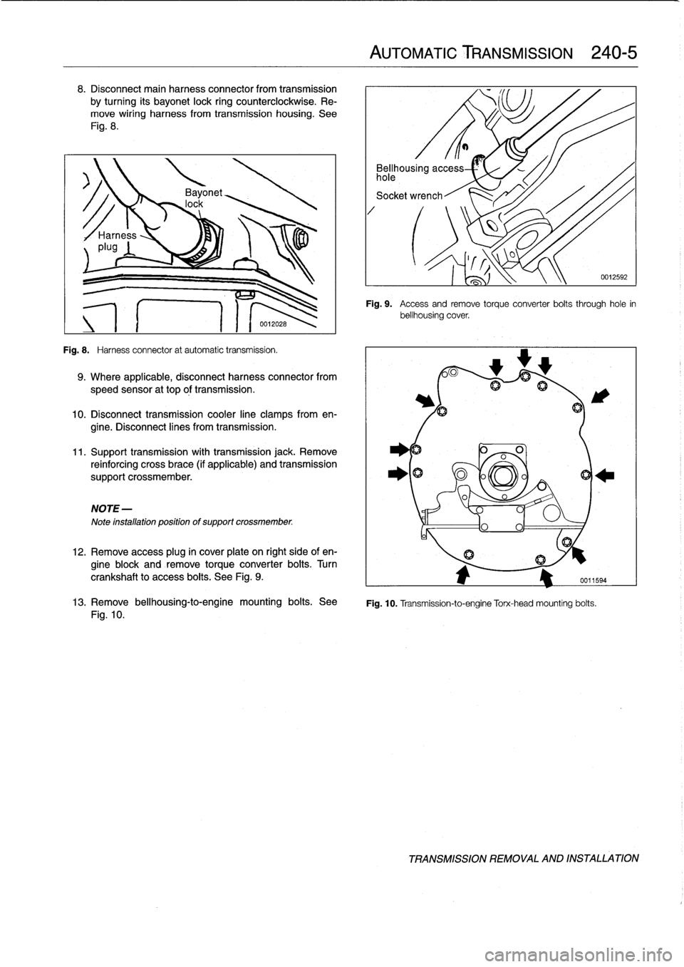
8
.
Disconnect
main
harness
connector
from
transmission
by
turning
its
bayonet
lock
ring
counterclockwise
.
Re-
move
wiring
harness
from
transmission
housing
.
See
Fig
.
8
.
Fig
.
8
.
Harness
connector
at
automatic
transmission
.
9
.
Where
applicable,
disconnect
harness
connector
from
speed
sensor
at
top
óf
transmission
.
10
.
Disconnect
transmission
cooler
line
clamps
from
en-
gine
.
Disconnect
lines
from
transmission
.
11
.
Support
transmission
with
transmission
jack
.
Remove
reinforcing
cross
brace
(if
applicable)
and
transmission
support
crossmember
.
NOTE-
Note
installation
positionof
support
crossmember
.
12
.
Remove
access
plug
in
cover
plate
on
right
side
of
en-
gine
block
and
remove
torqueconverter
bolts
.
Turn
crankshaft
to
access
boits
.
See
Fig
.
9
.
AUTOMATIC
TRANSMISSION
240-
5
Bellhousing
access
hole
Socket
wrench
Fig
.
9
.
Access
andremove
torque
converter
boits
through
hole
in
bellhousing
cover
.
0
A
fij
13
.
Remove
bellhousing-to-engine
mounting
bolts
.
See
Fig
.
10
.
Transmission-to-engine
Torx-head
mounting
bolts
.
Fig
.
10
.
0012592
TRANSMISSION
REMOVAL
AND
INSTALLATION
Page 236 of 759
250-2
GEARSHIFT
LINKAGE
5
.
Remove
driveshaft
.
See260
Driveshaft
.
9
.
Release
gearshift
lever
retaining
ring
from
below
by
turningspecial
tool
90°(
1
/4
turn)
counterclockwise
.
See
6
.
Support
transmission
with
transmission
jack
.
Remove
Fig
.
4
.
crossmember
from
rear
of
transmission
.
See
Fig
.
2
.
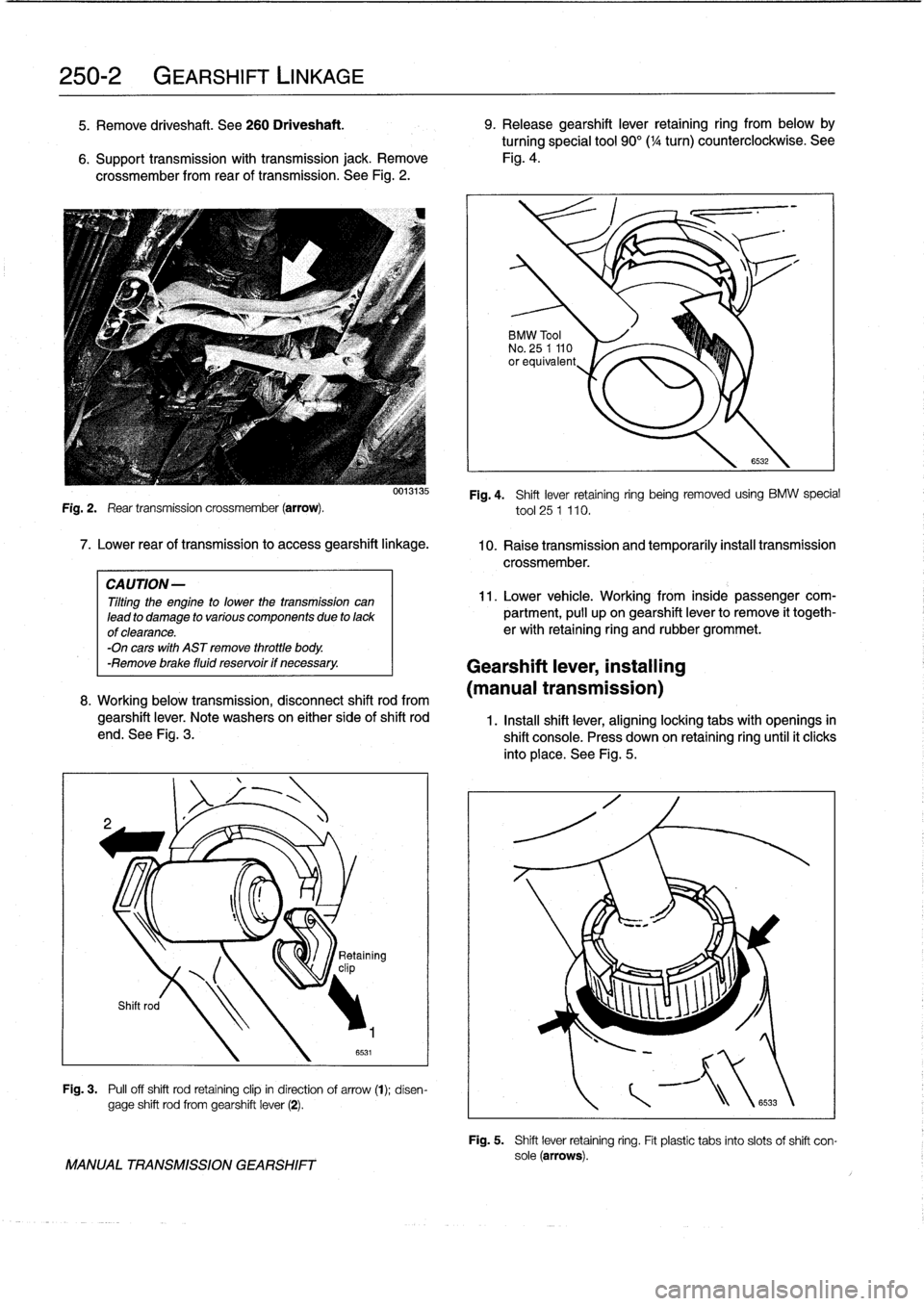
Fig
.
2
.
Rear
transmission
crossmember
(arrow)
.
7
.
Lower
rear
of
transmission
to
access
gearshift
linkage
.
CAUTION-
Tilting
the
engine
to
lower
thetransmission
can
lead
to
damage
to
various
componente
due
to
lackof
clearance
.
-On
cars
with
AST
remove
throttle
body
.
-Remove
brake
fluid
reservoir
if
necessary
.
0013135
8
.
Working
below
transmission,
disconnect
shift
rod
from
gearshift
lever
.
Note
washers
on
either
side
of
shift
rod
end
.
See
Fig
.
3
.
v
clip
Shift
rod
Fig
.
3
.
Pull
off
shift
rod
retaining
clip
in
direction
of
arrow
(t)
;
disen-
gage
shift
rod
from
gearshift
lever
(2)
.
MANUAL
TRANSMISSION
GEARSHIFT
BMW
Tool
No
.
25
1
110
orequivalent
Fig
.
4
.
Shift
lever
retaining
ring
being
removed
using
BMW
special
tool
25
1
110
.
10
.
Raise
transmission
and
temporarily
instan
transmission
crossmember
.
11
.
Lower
vehicle
.
Working
from
inside
passengercom-
partment,
pull
upon
gearshift
lever
to
remove
it
togeth-
erwith
retaining
ring
and
rubber
grommet
.
Gearshift
lever,
installing
(manual
transmission)
6532
1
.
Instan
shift
lever,
aligninglocking
tabs
with
openings
in
shift
console
.
Press
down
on
retaining
ring
until
it
clicks
into
place
.
See
Fig
.
5
.
\
Retaining
Fig
.
5
.
Shift
lever
retaining
ring
.
Fit
plastic
tabs
into
slots
of
shift
con-
sole(arrows)
.
Page 306 of 759
400-
4
BODY-GENERAL
INTERIOR
EQUIPMENT
E36
interiors
have
a
unique
character,
with
a
combínation
of
sporty
features
and
innovative
design
.
Al¡
body
versions
were
made
in
a
wide
choice
of
interior
and
exterior
colors
.
New
colors
with
matching
leather
and/or
fabric
upholstery
were
in-
troduced
for
each
model
year,
including
light-alloy
wheels
in
new
designs
.
Driving
comfort
is
enhanced
by
power
steering,
tilt
steering
wheel
(optional),
height-adjustable
front
seats,
and
electrical-
ly
adjustable
and
heated
rear-view
mirrors
.
Inside
thecar
there
are
reading
lights
at
four
seating
positions
.
Seats
and
Seat
Belts
NOTE-
Theseat
base
usedon
cars
with
pyrotechnic
seatbelt
Anatom¡cal
ly-correct
seats
are
constructed
from
polyure-
tensioners
is
not
interchangeable
with
the
earlier
seat
thane
foam
containing
areas
or
"zones"
of
different
firmness
.
base
.
The
seat
bases
have
steel
springs
for
added
support
and
strength
.
The
power
seats
are
provided
with
conveniently
lo-
Instruments
and
Controls
cated
switches
along
the
outside
edge
of
the
seat
.
Heated
seats
are
an
option
in
all
models
.
See
520
Seats
for
more
de-
Everything
in
the
interior
passenger
compartment
essential
tails
.
to
the
driver
is
logically
grouped
and
easy
to
reach
.
Al¡
instru-
ments
and
controls
havebeen
arranged
ergonomically
and
The
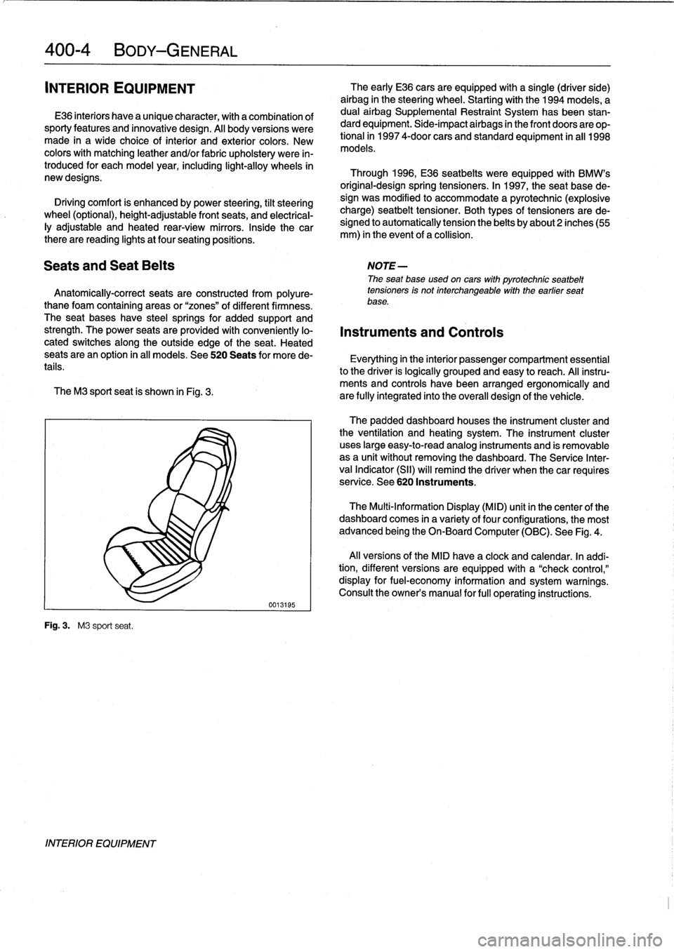
M3
sport
seat
is
shown
in
Fig
.
3
.
are
fully
integrated
into
the
overall
design
of
the
vehicle
.
Fig
.
3
.
M3
sport
seat
.
INTERIOR
EQUIPMENT
0013195
The
early
E36
cars
areequipped
with
a
single
(driver
side)
airbag
in
the
steering
wheel
.
Startingwith
the
1994
models,
a
dual
airbag
Supplemental
Restraint
System
has
been
stan-
dard
equipment
.
Side-impact
airbags
in
the
front
doors
are
op-
tional
in
1997
4-door
cars
and
standard
equipment
in
all
1998
models
.
Through
1996,
E36
seatbelts
were
equipped
with
BMW's
original-designspring
tensioners
.
In
1997,
the
seat
base
de-
sign
was
modified
to
accommodate
a
pyrotechnic
(explosive
charge)
seatbelt
tensioner
.
Both
types
of
tensioners
arede-
signed
to
automatically
tension
the
belts
by
about2
inches(55
mm)
in
the
event
of
a
collision
.
The
padded
dashboard
houses
the
instrument
cluster
and
the
ventilation
and
heating
system
.
The
instrument
cluster
uses
large
easy-to-read
analog
instruments
and
is
removable
as
a
unit
without
removing
the
dashboard
.
The
Service
Inter-
val
Indicator
(SII)
will
remind
the
driver
when
thecar
requires
service
.
See
620
Instruments
.
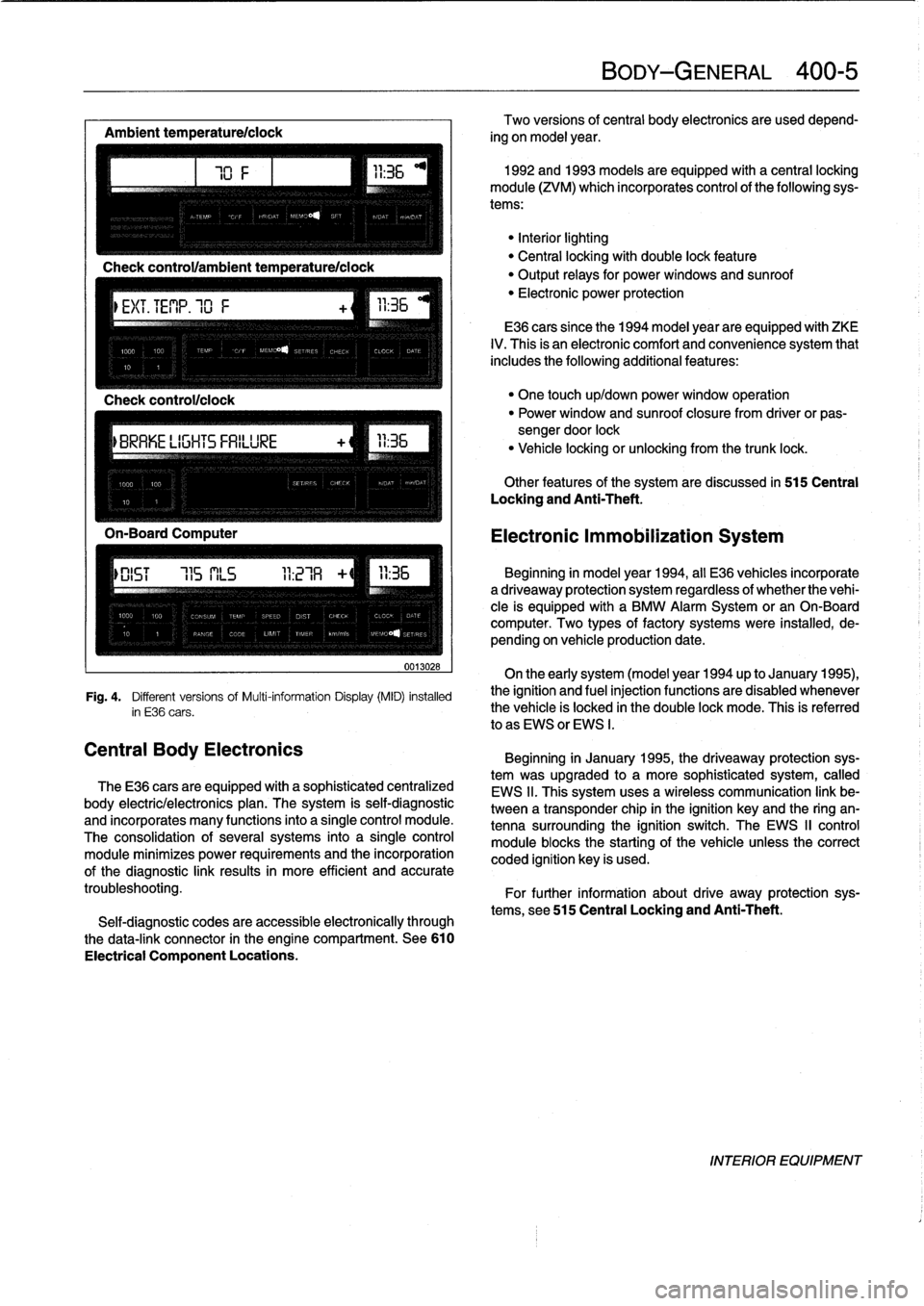
The
Multi-Information
Display
(MID)
unit
in
thecenter
of
the
dashboard
comes
in
a
variety
of
four
configurations,
the
most
advanced
being
the
On-Board
Computer
(OBC)
.
See
Fig
.
4
.
Al¡
versions
of
the
MID
have
a
clock
and
calendar
.
In
addi-
tion,
different
versions
areequipped
with
a
"check
control,"
display
for
fuel-economy
information
and
system
warnings
.
Consult
the
owner's
manual
for
fui¡
operating
instructions
.
Page 307 of 759
Ambient
temperaturelclock
MÍM
Aa
.Mi}rm
-Mil"
IMua~naa~u~itacar
"
za
.~
Central
Body
Electronics
0013028
Fig
.
4
.
Different
versionsof
Multi-information
Display(MID)
installed
in
E36
cars
.
The
E36
cars
are
equipped
with
a
sophisticated
centralized
body
electric/electronics
plan
.
The
system
is
self-diagnostic
and
incorporates
many
functions
into
a
single
control
module
.
The
consolidation
of
several
systems
into
a
single
control
module
minimizes
power
requirements
and
the
incorporation
of
the
diagnostic
link
results
in
more
efficient
and
accurate
troubleshooting
.
Self-diagnostic
codes
are
accessible
electronically
through
the
data-link
connector
in
the
engine
compartment
.
See610
Electrical
Component
Locations
.
BODY-GENERAL
400-
5
Two
versions
of
central
body
electronics
are
used
depend-
ing
on
model
year
.
1992
and
1993
models
are
equipped
with
a
central
locking
module
(ZVM)
which
incorporates
control
of
the
following
sys-
tems
:
"Interiorlighting
"
Central
locking
with
double
lock
feature
"
Output
relays
for
powerwindows
and
sunroof
"
Electronic
power
protection
E36
cars
since
the
1994
model
year
are
equipped
with
ZKE
IV
.
This
is
an
electronic
comfort
and
convenience
system
that
includes
the
following
additional
features
:
"
One
touch
up/down
power
window
operation
"
Power
window
and
sunroof
closure
from
driver
or
pas-
sengerdoor
lock
"
Vehicle
locking
or
unlocking
from
the
trunk
lock
.
Other
features
of
the
system
are
discussed
in
515
Central
Locking
and
Anti-Theft
.
Electronic
Immobilization
System
Beginning
in
model
year
1994,
all
E36
vehicles
incorporate
adriveaway
protection
system
regardless
of
whether
the
vehi-
cle
is
equipped
with
a
BMW
Alarm
System
or
an
On-Board
computer
.
Two
types
of
factory
systems
were
installed,
de-
pending
on
vehicle
production
date
.
On
the
early
system
(model
year
1994
up
to
January
1995),
the
ignition
and
fuel
injection
functions
are
disabled
whenever
the
vehicle
is
locked
in
the
double
lock
mode
.
This
is
referred
lo
as
EWS
or
EWS
I
.
Beginning
in
January
1995,
the
driveaway
protection
sys-
tem
was
upgraded
to
a
more
sophisticated
system,
called
EWS
II
.
This
system
uses
a
wireless
communication
link
be-
tween
a
transponder
chip
in
the
ignition
keyand
the
ring
an-
tenna
surrounding
the
ignition
switch
.
The
EWS
II
control
module
blocksthe
starting
of
the
vehicle
unlessthe
correct
coded
ignition
key
is
used
.
For
further
information
about
drive
away
protection
sys-
tems,
see
515
Central
Locking
and
Anti-Theft
.
INTERIOR
EQUIPMENT
Page 313 of 759
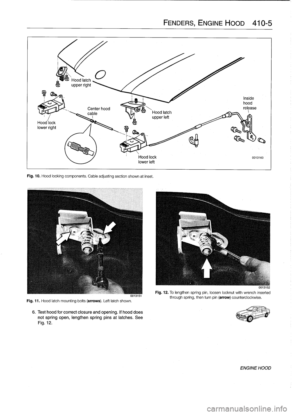
Center
hood
,
00--&---
cable
Hood
latch
_
I
upperleft
Fig
.
10
.
Hood
locking
components
.
Cable
adjusting
section
shown
at
inset
.
Fig
.
11
.
Hood
latch
mounting
bolts
(arrows)
.
Left
latch
shown
.
Hood
lock
0013160
lower
left
6
.
Test
hood
for
correct
closure
and
opening
.
If
hooddoes
notspring
open,
lengthen
springpins
at
latches
.
See
Fig
.
12
.
FENDERS,
ENGINE
HOOD
410-5
001aio
Fig
.
12
.
To
lengthen
spring
pin,
loosen
locknut
with
wrench
inserted
through
spring,
then
turn
pin
(arrow)
counterclockwise
.
ENGINE
HOOD
Page 328 of 759
510-
6
EXTERIOR
TRIM,
BUMPERS
Rear
bumper
impact
absorber,replacing
1
.
Remove
bumperas
described
above
.
2
.
Remove
luggage
compartment
floor
covering
.
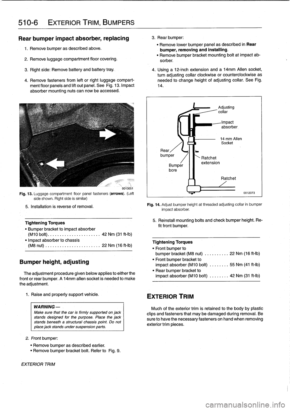
Fig
.
13
.
Luggage
compartment
floor
panel
fasteners
(arrows)
.
(Left
side
shown
.
Righf
side
is
similar)
5
.
Installation
ís
reverse
of
removal
.
Bumper
height,
adjusting
Tightening
Torques
"
Bumper
bracket
to
impact
absorber
(M10
bolt)
.
............
.
...
..
..
.
42
Nm
(31
ft-lb)
"
Impact
absorber
to
chassis
(M8
nut)
.
.
..........
.
......
.
.
.
.
22
Nm
(16
ft-Ib)
The
adjustment
procedure
given
below
applies
to
either
the
frontor
rear
bumper
.
A
14mm
allen
socket
is
needed
to
make
the
adjustment
.
1
.
Raise
and
properly
support
vehicle
.
WARNING
-
Make
sure
that
the
car
is
firmly
supported
on
jack
stands
designed
for
the
purpose
.
Place
the
jack
stands
beneath
a
structural
chassis
point
.
Do
not
place
jack
stands
under
suspension
parts
.
2
.
Front
bumper
:
"
Remove
bumper
as
described
earlier
.
"
Remove
bumper
bracket
bolt
.
Refer
to
Fig
.
9
.
EXTERIOR
TRIM
3
.
Rear
bumper
:
"
Remove
lower
bumper
panel
as
described
in
Rear
bumper,
removing
and
installing
.
"
Remove
bumper
bracket
mounting
bolt
at
impact
ab-
sorber
.
3
.
Right
side
:
Remove
battery
and
battery
tray
.
4
.
Using
a
12-inch
extension
and
a
l4mm
Allen
socket,
turn
adjusting
collar
clockwise
or
counterclockwise
as
4
.
Remove
fasteners
from
left
or
right
luggage
compart-
needed
to
change
height
of
adjusting
collar
.
See
Fig
.
ment
floor
panels
and
lift
out
panel
.
See
Fig
.
13
.
Impact
14
.
absorber
mounting
nuts
can
now
be
accessed
.
~4
EXTERIOR
TRIM
Ratchet
extension
Adjusting
collar
Impact
absorber,
14
mm
Allen
Socket
Ratchet
0012073
Fig
.
14
.
Adjust
bumper
height
at
threaded
adjusting
collar
in
bumper
impact
absorber
.
5
.
Reinstall
mounting
bolts
and
check
bumper
height
.
Re-
fit
front
bumper
.
Tightening
Torques
"
Front
bumper
to
bumper
bracket
(M8
nut)
......
.
..
.
22
Nm
(16
ft-Ib)
"
Front
bumper
bracket
to
impact
absorber
(M10
bolt)
........
55
Nm
(41
ft-Ib)
"
Rear
bumper
bracket
to
impact
absorber
(M10
bolt)
........
42
Nm
(31
ft-Ib)
Much
of
the
exteriortrim
is
retained
to
the
body
by
plasticclips
and
fasteners
that
may
be
damaged
during
removal
.
Be
sure
to
have
the
necessary
fasteners
onhand
when
removing
exterior
trim
pieces
.
Page 397 of 759
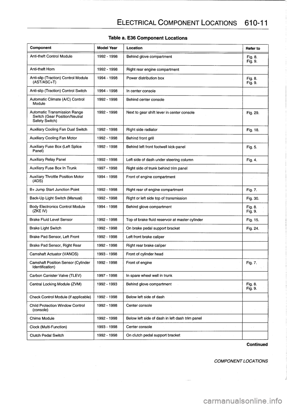
Table
a
.
E36
Component
Locations
Component
Model
Year
Location
Refer
to
Anti-theft
Control
Module
1992-1998
Behind
glove
compartment
Fig
.
8
.
Fig
.
9
.
Anti-theft
Horn
1
1992-1998
1
Right
rear
engine
compartment
Anti-slip
(Traction)
Control
Module
1994-1998
Power
distribution
box
Fig
.
8
.
(AST/ASC+T)
Fig
.
9
.
Anti-slip
(Traction)
Control
Switch
1994-1998
In
center
console
Automatic
Climate
(A/C)
Control
1992-1998
Behind
center
console
Module
AutomaticTransmission
Range
1992-1998
~
Next
to
gear
shift
lever
in
center
console
Fig
.
29
.
Switch
(Gear
Position/Neutral
Safety
Switch)
Auxiliary
Cooling
Fan
Dual
Switch
1992-1998
Right
side
radiator
1
Fig
.
18
.
Auxiliary
Cooling
Fan
Motor
1992-1998
Behind
front
grill
Auxiliary
Fuse
Box
(Left
Splice
1992-1998
I
Behind
left
front
footwell
kick-panel
Panel)
Auxiliary
RelayPanel
1
1992-1998
1
Left
side
of
dash
under
steering
column
Auxiliary
Fuse
Box
In
Trunk
1
1997-1998
1
Right
sideof
trunk
behind
trim
panel
AuADSry
ThrottlePosition
Motor
11994-1998
Front
of
engine
compartment
B+
Jump
Start
Junction
Point
1992-1998
Right
rear
of
engine
compartment
Fig
.
7
.
Back-Up
Light
Switch
(Manual)
1992-1998
Right
or
left
side
top
of
transmission
Fig
.
30
.
Body
Electronics
Control
Module
1994-1998
Behindglove
compartment
Fig
.
8
.
(ZKE
IV)
Fig
.
9
.
Brake
Fluid
Level
Sensor
1992-1998
Top
of
brake
fluid
reservoir
at
master
cylinder
Fig
.
15
.
Brake
Light
Switch
1
1992-1998
1
On
brake
pedal
supportbracket
Brake
Pad
Sensor,
Left
Front
1
1992-1998
1
Left
front
brake
caliper
Brake
Pad
Sensor,
Right
Rear
1992-1998
Right
rear
brake
caliper
Camshaft
Actuator
(VANOS)
1993-1998
Front
of
cylinder
head
Camshaft
Position
Sensor
(Cylinder
1992-1998
Front
of
engine
Identification)
Carbon
Canister
Valve
(TLEV)
1
1997-1998
1
In
sparewheel
well
in
trunk
ELECTRICAL
COMPONENT
LOCATIONS
610-11
Fig
.
5
.
Fig
.
4
.
Fig
.
24
.
Fig
.
7
.
Central
Locking
Module
(ZVM)
11992-1993
1
Behindglove
compartment
I
Fig
.
8
.
Fig
.
9
.
Check
Control
Module
(if
applicable)
1
1992
-
1998
1
Below
left
side
of
dash
Child
Protection
Window
Control
1992-1998
Center
console
(console)
Chime
Module
1992-1998
Below
left
side
of
dash
inleft
dash
trim
panel
Clock
(Multi-Function)
1993-1998
Center
console
Clutch
Pedal
Switch
1992-1998
On
clutch
pedal
support
bracket
Continued
COMPONENT
LOCATIONS
Page 402 of 759
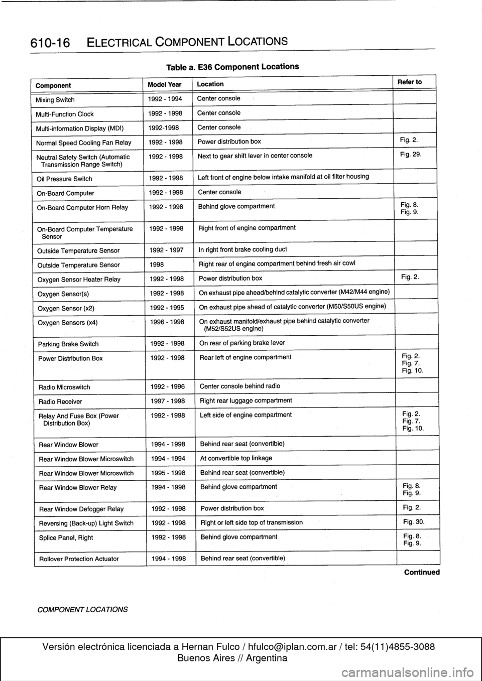
610-16
ELECTRICAL
COMPONENT
LOCATIONS
Component
Model
Year
Location
Refer
to
MixingSwitch
1992-1994
Center
console
Multi-Function
Clock
1992-1998
Center
console
Multi-information
Display
(MDI)
1992-1998
Center
console
Normal
Speed
Cooling
Fan
Relay
1992-1998
Power
distribution
box
Fig
.
2
.
Neutral
SafetySwitch
(Automatic
1992-1998
Next
to
gear
shift
lever
in
center
console
Fig
.
29
.
Transmission
Range
Switch)
Oil
Pressure
Switch
1992-1998
Left
front
of
engine
below
intake
manifold
at
oil
filter
housing
On-Board
Computer
1992-1998
Center
console
On-BoardComputerHorn
Relay
1992-1998
Behind
glove
compartment
Fig
.
8
.
Fig
.
9
.
On-Board
Computer
Temperature
11992-1998
I
Right
front
of
engine
compartment
Sensor
Outside
Temperature
Sensor
1992-1997
Inright
front
brake
cooling
duct
Outside
Temperature
Sensor
1998
Right
rear
of
engine
compartment
behind
fresh
air
cowl
Oxygen
Sensor
HeaterRelay
1992-1998
Power
distribution
box
Fig
.
2
.
Oxygen
Sensor(s)
1992-1998
On
exhaust
pipe
ahead/behind
catalytic
converter
(M42/M44
engine)
Oxygen
Sensor
(x2)
1992-1995
On
exhaust
pipe
ahead
of
catalytic
converter
(M50/S50US
engine)
Oxygen
Sensors
(x4)
1996-1998
On
exhaust
manifold/exhaust
pípe
behind
catalytic
converter
(M52/S52US
engine)
Parking
Brake
Switch
1
1992-1998
I
On
rear
of
parking
brake
lever
Power
Distribution
Box
11992-1998
I
Rear
left
of
engine
compartment
I
Fig
.
2
.
Fig
.
7
.
Fig
.
10
.
Radio
Microswitch
1992
-
1996
Center
console
behind
radio
Radio
Receíver
1
1997-1998
1
Right
rear
luggage
compartment
Relay
And
Fuse
Box
(Power
1992-1998
I
Left
side
of
engine
compartment
I
Fig
.
2
.
Distribution
Box)
Fig
.
7
.
Fig
.
10
.
Rear
Window
Blower
1994-1998
Behind
rear
seat
(convertible)
Rear
Window
Blower
Microswitch
1994-1994
At
convertible
top
linkage
Rear
Window
Blower
Microswitch
1995-1998
Behind
rear
seat
(convertible)
Rear
Window
BlowerRelay
11994-1998
Behind
glove
compartment
Fig
.
8
.
Fig
.
9
.
Fig
.
2
.
Fig
.
30
.
Fig
.
8
.
Rear
Window
DefoggerRelay
Reversing
(Back-up)
Light
Switch
SplicePanel,
Right
Rollover
Protection
Actuator
11994-1998
COMPONENT
LOCATIONS
Table
a
.
E36
Component
Locations
1992-1998
1992-1998
1992-1998
Power
distribution
box
Right
or
left
side
top
of
transmission
Behind
glove
compartment
Behind
rear
seat
(convertible)
Fig
.
9
.
Continued
Page 406 of 759
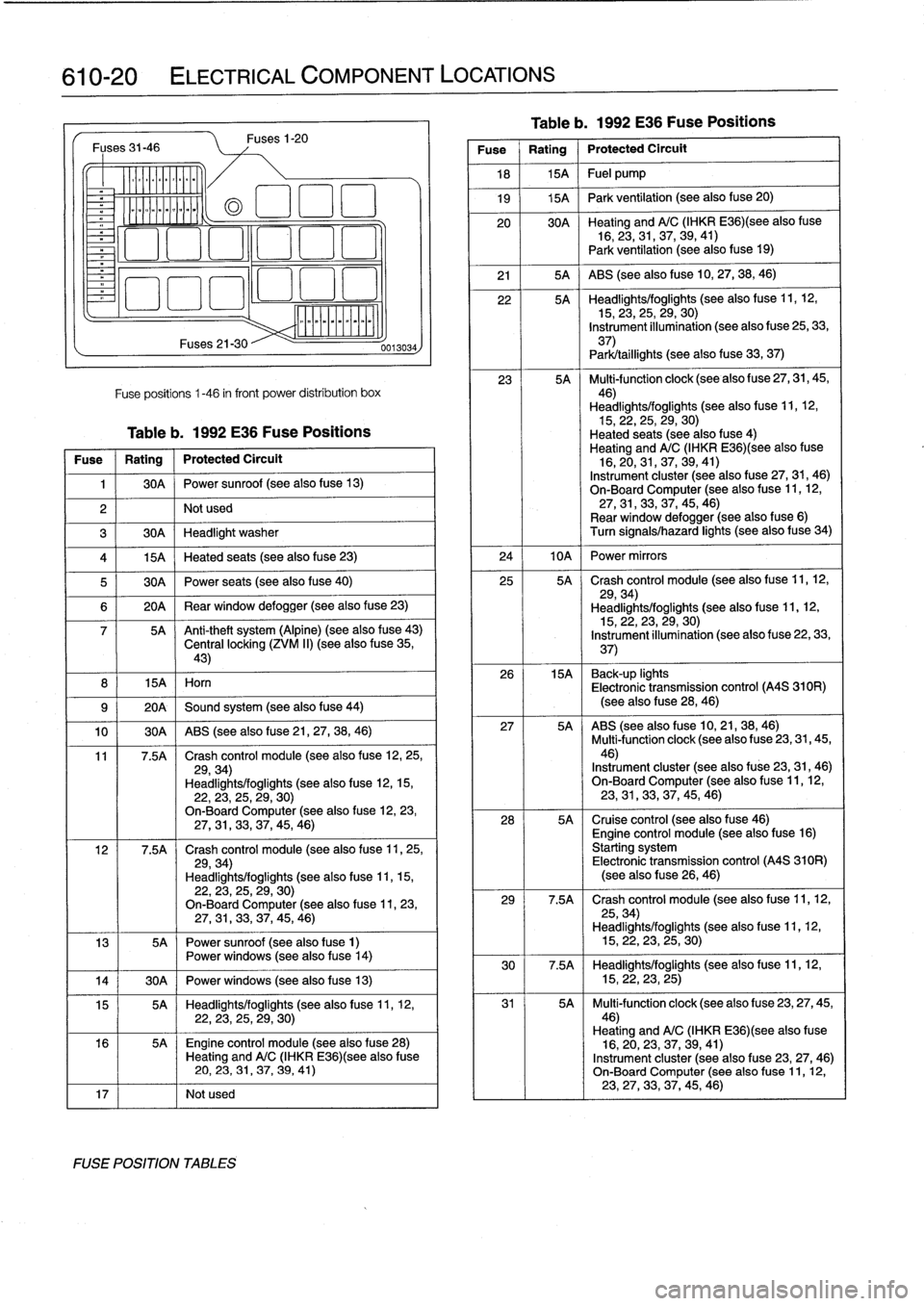
610-20
ELECTRICAL
COMPONENT
LOCATIONS
Fuses
31-46
o_
~oomoo
ommmo~
8
I
15A
I
Horn
Fuses21-30
Fuses
1-20
Fuse
positions
1-46
in
front
power
distribution
box
Table
b
.
1992
E36
Fuse
Positions
Fuse
1
Rating
1
Protected
Circuit
1
1
30A
1
Power
sunroof
(see
also
fuse
13)
2
I
I
Not
used
3
1
30A
1
Headlight
washer
(a
El
1
:1
El
4
1
15A
1
Heated
seats
(see
also
fuse
23)
5
1
30A
1
Power
seats
(see
also
fuse
40)
6
1
20A
1
Rear
window
defogger
(see
also
fuse
23)
7
5A
~
Anti-theft
system
(Alpine)
(see
also
fuse
43)
Central
locking
(ZVM
II)
(see
also
f
use
35,43)
9
(
20A
1
Sound
system
(see
also
fuse
44)
10
1
30A
1
ABS
(see
also
f
use
21,
27,
38,
46)
11
7
.5A
Crash
control
module
(seealso
fuse
12,25,
29,34)
Headlights/foglights
(see
also
fuse
12,15,22,23,
25,29,
30)
On-BoardComputer
(seealsofuse
12,
23,27,31,
33,37,
45,
46)
12
7
.5A
Crash
control
module
(see
also
f
use
11,
25,
29,34)
Headlights/foglights
(seealsofuse
11,15,
22,
23,25,
29,
30)
On-BoardComputer
(see
also
fuse
11,
23,27,
31,33,
37,45,
46)
13
5A
Power
sunroof
(see
also
fuse
1)
Power
windows
(see
also
f
use
14)
14
j
30A
1
Power
windows
(see
also
fuse
13)
15
5A
Headlights/foglights
(see
also
fuse
11,
12,22,
23,
25,29,
30)
16
5A
~
Engine
control
module
(seealsofuse
28)
Heating
andA/C
(IHKR
E36)(see
alsofuse
20,
23,
31,37,
39,
41)
17
I
I
Notused
FUSE
POSITION
TABLES
0013034
Table
b
.
1992
E36
Fuse
Positions
Fuse
Rating
Protected
Circult
18
1
15A
1
Fuel
pump
19
j
15A
1
Park
ventilation
(see
also
fuse
20)
20
30A
~
Heating
andA/C
(IHKR
E36)(see
alsofuse
16,23,31,37,39,
41)
Park
ventilation
(see
also
f
use
19)
21
1
5A
{
ABS
(see
also
fuse
10,27,
38,46)
22
5A
Headlights/foglights
(see
also
f
use
11,12,15,
23,
25,29,
30)
Instrument
illumination
(see
also
fuse
25,33,
37)
Park/taillights
(seealsofuse
33,
37)
23
5A
Multi-function
clock
(see
also
fuse
27,
31,
45,
46)
Headlights/foglights
(see
also
fuse
11,12,15,22,25,
29,30)
Heated
seats
(seealsofuse
4)
Heating
andA/C
(IHKR
E36)(see
alsofuse
16,20,31,37,39,
41)
Instrument
cluster
(see
also
fuse
27,31,
46)
On-Board
Computer
(seealso
fuse
11,
12,
27,31,
33,
37,45,
46)
Rear
window
defogger
(see
alsofuse
6)
Turn
signals/hazard
lights
(seealsofuse
34)
24
I
10A
I
Power
mirrors
25
5A
Crash
control
module
(see
also
f
use
11,12,
29,34)
Headlights/foglights
(see
also
fuse
11,12,15,22,23,29,
30)
Instrument
illumination
(see
also
fuse
22,
33,
37)
26
15A
~
Back-up
lights
Electronic
transmission
control
(A4S
310R)
(seealsofuse
28,46)
27
5A
ABS
(see
also
fuse
10,21,38,
46)
Multi-function
clock
(see
also
fuse
23,
31,
45,46)
Instrument
cluster
(see
also
fuse
23,
31,46)
On-BoardComputer
(see
also
fuse
11,12,23,
31,
33,37,45,
46)
28
5A
Cruise
control
(see
alsofuse
46)
Engine
control
module
(see
alsofuse
16)
Starting
system
Electronic
transmission
control
(A4S
310R)
(see
also
f
use
26,
46)
29
7
.5A
Crash
control
module
(see
also
fuse
11,12,
25,34)
Headlights/foglights
(see
also
fuse
11,12,15,22,23,
25,
30)
30
7
.5A
Headlights/foglights
(see
also
fuse
11,
12,
15,22,23,
25)
31
5A
Multi-function
clock
(see
alsofuse
23,27,
45,46)
Heating
andA/C
(IHKR
E36)(see
also
fuse
16,20,
23,
37,39,
41)
Instrument
cluster
(seealso
fuse
23,
27,46)
On-Board
Computer
(see
also
f
use
11,12,23,27,
33,
37,45,
46)
Page 407 of 759
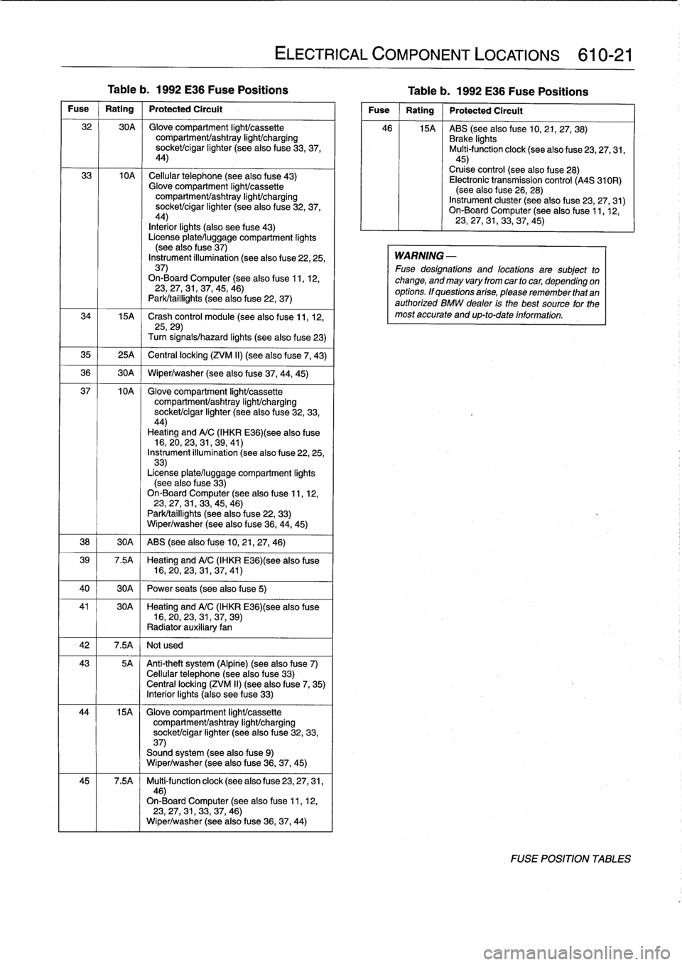
Table
b
.
1992
E36
Fuse
Positions
Table
b
.
1992
E36
Fuse
Positions
Fuse
Rating
Protected
Circuit
32
30A
Glove
compartment
light/cassette
compartmenVashtray
light/charging
socket/cigar
lighter
(see
also
fuse
33,37,
44)
33
10A
Cellular
telephone
(seealsofuse
43)
Glove
compartment
light/cassette
compartment/ashtray
IighUcharging
sockeUcigar
lighter
(seealsofuse
32,
37,
44)
Interiorlights
(also
see
fuse
43)
License
plate/luggage
compartment
lights
(see
also
f
use
37)
Instrument
íllumination
(see
also
fuse
22,25,
37)
On-Board
Computer
(see
also
fuse
11,12,23,27,31,37,45,
46)
Park/taillights
(seealso
fuse
22,
37)
34
15A
~
Crash
control
module
(see
also
fuse
11,
12,
25,29)
Turn
signals/hazard
lights
(seealsofuse
23)
35
1
25A
j
Central
locking
(ZVM
II)
(see
alsofuse
7,
43)
36
1
30A
1
Wiper/washer
(seealsofuse
37,44,
45)
37
10A
Glove
compartment
IighUcassette
compartmenVashtray
light/charging
socket/cigar
lighter
(see
also
fuse
32,33,
44)
Heating
andA/C
(IHKR
E36)(see
alsofuse
16,
20,23,31,
39,41)
Instrument
illumination
(see
also
fuse
22,25,
33)
License
plate/luggage
compartment
lights
(see
also
fuse
33)
On-Board
Computer
(see
also
fuse
11,12,23,27,31,33,45,
46)
Park/taillights
(see
alsofuse
22,
33)
Wiper/washer
(see
also
fuse
36,
44,
45)
38
1
30A
1
ABS
(see
also
fuse
10,21,27,
46)
39
7
.5A
Heating
andA/C
(IHKR
E36)(see
also
fuse
16,20,
23,
31,37,
41)
40
1
30A
1
Power
seats
(see
also
fuse
5)
41
30A
~
Heating
andA/C
(IHKR
E36)(see
alsofuse
16,20,23,
31,
37,
39)
Radiator
auxiliary
fan
42
I
7
.5A
I
Not
used
43
5A
Anti-theft
system
(Alpine)
(see
also
fuse
7)
Cellular
telephone
(seealsofuse
33)
Centrallocking
(ZVM
II)
(see
also
f
use
7,
35)
Interiorlights
(also
see
fuse
33)
44
15A
Glove
compartment
light/cassette
compartmenVashtray
light/charging
sockeUcigar
lighter
(see
also
fuse
32,
33,
37)
Sound
system
(see
also
fuse
9)
Wiper/washer
(see
also
fuse
36,37,
45)
45
7
.5A
Multi-function
clock
(see
also
fuse
23,
27,
31,
46)
On-Board
Computer
(see
also
fuse
11,12,
23,
27,31,33,
37,46)
Wiper/washer
(see
also
fuse
36,37,
44)
ELECTRICAL
COMPONENT
LOCATIONS
610-21
Fuse
Rating
Protected
Circuít
46
15A
ABS
(see
also
fuse
10,21,27,
38)
Brake
lights
Multi-function
clock
(seealso
fuse
23,27,31,
45)
Cruise
control
(see
also
fuse
28)
Electronic
transmission
control
(A4S
310R)
(see
also
f
use
26,
28)
Instrument
cluster
(seealsofuse
23,
27,31)
On-Board
Computer
(see
also
f
use
11,12,
23,
27,31,33,
37,45)
WARNING
-
Fuse
designations
and
locations
are
subject
to
change,
and
may
vary
from
car
tocar,
depending
on
options
.
If
questions
arise,
please
remember
that
an
authorized
BMW
dealer
is
the
best
source
for
the
most
accurate
and
up-to-date
information
.
FOSE
POSITION
TABLES