coolant temp sensor BMW M3 1998 E36 Owner's Manual
[x] Cancel search | Manufacturer: BMW, Model Year: 1998, Model line: M3, Model: BMW M3 1998 E36Pages: 759
Page 182 of 759
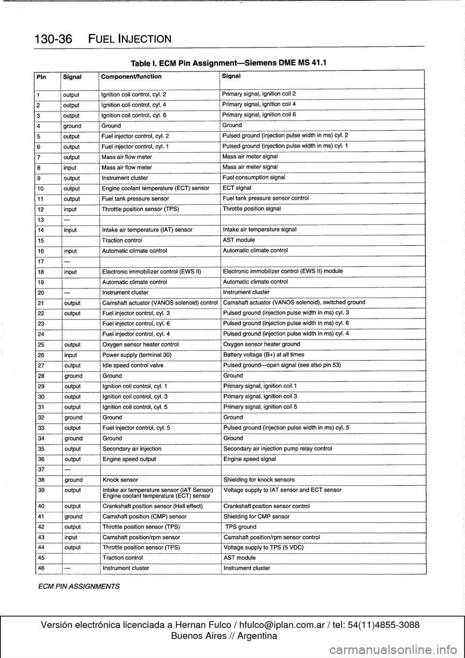
130-
3
6
FUEL
INJECTION
Pin
1
Signal
1
Componentffunction
1
Signal
1
output
Ignition
coil
control,
cyl
.
2
Primary
signal,
ignition
coil
2
2
output
Ignition
coil
control,
cyl
.
4
Primary
signal,
ignitioncoil
4
3
output
Ignition
coil
control,
cyl
.
6
Primary
signal,
ignition
coil
6
4
ground
Ground
Ground
5
output
Fuel
injectorcontrol,
cyl
.
2
Pulsed
ground
(injection
pulse
width
in
ms)
cyl
.
2
6
output
Fuel
injectorcontrol,
cyl
.
1
Pulsed
ground
(injection
pulse
width
in
ms)
cyl
.
1
7
output
Mass
air
flow
meter
Mass
air
meter
signal
8
input
Mass
air
flow
meter
Mass
air
meter
signal
9
output
Instrument
cluster
Fuel
consumption
signal
10
output
Engine
coolant
temperature
(ECT)
sensor
ECT
signal
11
output
Fueltankpressure
sensor
Fueltankpressure
sensor
control
12
input
Throttleposition
sensor
(TPS)
Throttleposition
signal
13
-
14
input
Intake
air
temperature
(IAT)
sensor
Intake
air
temperature
signal
15
Traction
control
AST
module
16
input
Automatic
climate
control
Automatic
climate
control
17
18
input
Electronic
immobilizer
control
(EWS
II)
Electronic
immobilizer
control
(EWS
II)
module
19
Automatic
climate
control
Automatic
climate
control
20
-
Instrument
cluster
Instrument
cluster
21
output
Camshaft
actuator
(VANOS
solenoid)
control
Camshaft
actuator
(VANOS
solenoid),
switched
ground
22
output
Fuel
injectorcontrol,
cyl
.
3
Pulsed
ground
(injection
pulse
width
in
ms)
cyl
.
3
23
Fuel
injectorcontrol,
cyl
.
6
Pulsed
ground
(injection
pulse
width
in
ms)
cyl
.
6
24
Fuel
injectorcontrol,
cyl
.
4
Pulsed
ground
(injection
pulse
width
in
ms)
cyl
.
4
25
output
Oxygen
sensor
heater
control
Oxygen
sensor
heater
ground
26
input
Power
supply
(terminal
30)
Battery
voltage(B+)
at
all
times
27
output
Idle
speed
control
valve
Pulsed
ground-open
signal
(see
also
pin
53)
28
ground
Ground
Ground
29
output
Ignition
coil
control,
cyl
.
1
Primary
signal,
ignition
coíl
1
30
output
Ignition
coil
control,
cyl
.
3
Primary
signal,
ignition
coil
3
31
output
Ignition
coil
control,
cyl
.
5
Primary
signal,
ignition
coil
5
32
ground
Ground
Ground
33
output
Fuel
injector
control,
cyl
.
5
Pulsedground
(injection
pulsewidth
in
ms)
cyl
.
5
34
ground
Ground
Ground
35
output
Secondary
air
injection
Secondary
air
injection
pump
relay
control
36
output
Engine
speed
output
Engine
speed
signal
37
-
38
ground
Knock
sensor
Shielding
for
knock
sensors
39
output
Intake
air
temperature
sensor
(IAT
Sensor)
Voltagesupply
to
IAT
sensor
and
ECT
sensorEngine
coolant
temperature
(ECT)
sensor
40
output
Crankshaft
position
sensor
(Hall
effect)
Crankshaft
position
sensor
control
41
ground
Camshaft
position
(CMP)
sensor
Shielding
for
CMP
sensor
42
output
Throttle
position
sensor
(TPS)
TPS
ground
43
input
Camshaft
position/rpm
sensor
Camshaft
position/rpm
sensor
control
44
output
Throttle
position
sensor
(TPS)
Voltagesupply
to
TPS
(5
VDC)
45
Traction
control
AST
module
46
-
Instrument
cluster
Instrument
cluster
ECM
PIN
ASSIGNMENTS
Table
I.
ECM
Pin
Assignment-Siemens
DME
MS
41
.1
Page 195 of 759
170
Radiator
and
Cooling
System
GENERAL
.
.
.....
.
...
.
.
.
.
.
....
.
.
.
.
.
.
.
.170-1
Coolant
Pump
and
Thermostat
........
.
.
.
.
170-1
Radiator
and
Expansion
Tank
.........
.
...
170-1
Cooling
Fans
.
....
.
.
.
.
.
.
.
.
.
.....
.
......
170-2
Warnings
and
Cautions
.
.
.
.
.
.
.
.
.
.
.
.
...
.
.
.
170-2
TROUBLESHOOTING
...
.
.
.
...
.
.
.
.
.
.
.
.
.170-2
Cooling
System
Pressure
Test
...
.
.
.
.
.
.
.
.
.
170-3
Thermostat
Quick
Check
.
.
.
.
...
.
.
.
.
.
.
.
.
.
170-3
Temperature
Gauge
Quick
Check
.
.
.
.
.
.
.
.
.
170-3
Cooling
fan,
testing
.
.
.
.
........
.
.
.
.
.
.
.
.
.
170-4
COOLING
SYSTEM
SERVICE
.
.
.
.
.
.
.
.
.
.
170-5
Coolant,draining
and
filling
.
.
......
.
.
.
.
.
..
170-5
Cooling
system,
bleeding
(radiator
with
integral
expansion
tank)
.....
170-6
GENERAL
This
section
covers
repair
and
troubleshooting
information
for
the
engine
cooling
system
.
For
heater
core
and
related
heating
and
air
conditioning
components,
see640
Heating
and
Air
Conditioning
.
Coolant
Pump
and
Thermostat
A
centrifuga¡-type
coolant
pump
is
mounted
to
the
front
of
the
engíne
.
The
belt-driven
pump
circulates
coolant
through
the
system
whenever
the
engíne
is
running
.
A
thermostat
con-
trols
the
flow
of
coolant
into
the
radiator
.
When
the
engíne
is
cold
the
thermostat
is
closed
so
coolant
bypasses
the
radiator,
recirculating
from
the
engíne
directly
back
to
the
pump
.
When
the
engíne
reaches
operating
tem-
perature,
the
thermostat
opens
and
coolant
circulates
through
the
whole
system
including
the
radiator
.
Radiator
and
Expansion
Tank
The
radiator
is
a
crossflow
design
.
A
translucent
expansion
tank
provides
for
coolant
expansion
at
higher
temperatures
and
easy
monitoringof
the
coolant
leve¡
.
On
4-cylinder
modeis,
the
radiator
expansion
tank
is
integral
with
the
radiator
.
See
Fig
.
1
.
RADIATOR
AND
COOLING
SYSTEM
170-1
Belt-driven
cooling
fan,
replacing
.
.......
.
.
.
170-7
Electric
cooling
fan,
replacing
.
.
.
.....
.
.
.
.
.
170-8
Auxiliary
cooling
fan,
replacing
.
.
.....
.
.
.
.
.
170-8
Thermostat,
replacing
.
.
.
.
.
.
.
.
.
.....
.
.
.
.
.
170-9
Coolant
pump,
replacing
..........
.
.
.
.
.
.
170-10
RADIATOR
SERVICE
.....
.
......
.
.
.
.
.
.
170-11
Radiator,
removing
and
installing
....
.
.
.
.
.
.
170-11
TABLES
a
.
Coolant
Temperature
Sensor
Wire
Colors
...
.
..
.
.
170-3b
.
Auxiliary
Cooling
Fan
Switching
Temperatures
.:.
.170-4
c
.
Auxiliary
Cooling
Fan
Temperature
Switch
Tests
..
..
.
...
...
.
.............
.
..
.
.
170-5d
.
Cooling
System
Capacities
..............
..
.
.
.
170-6
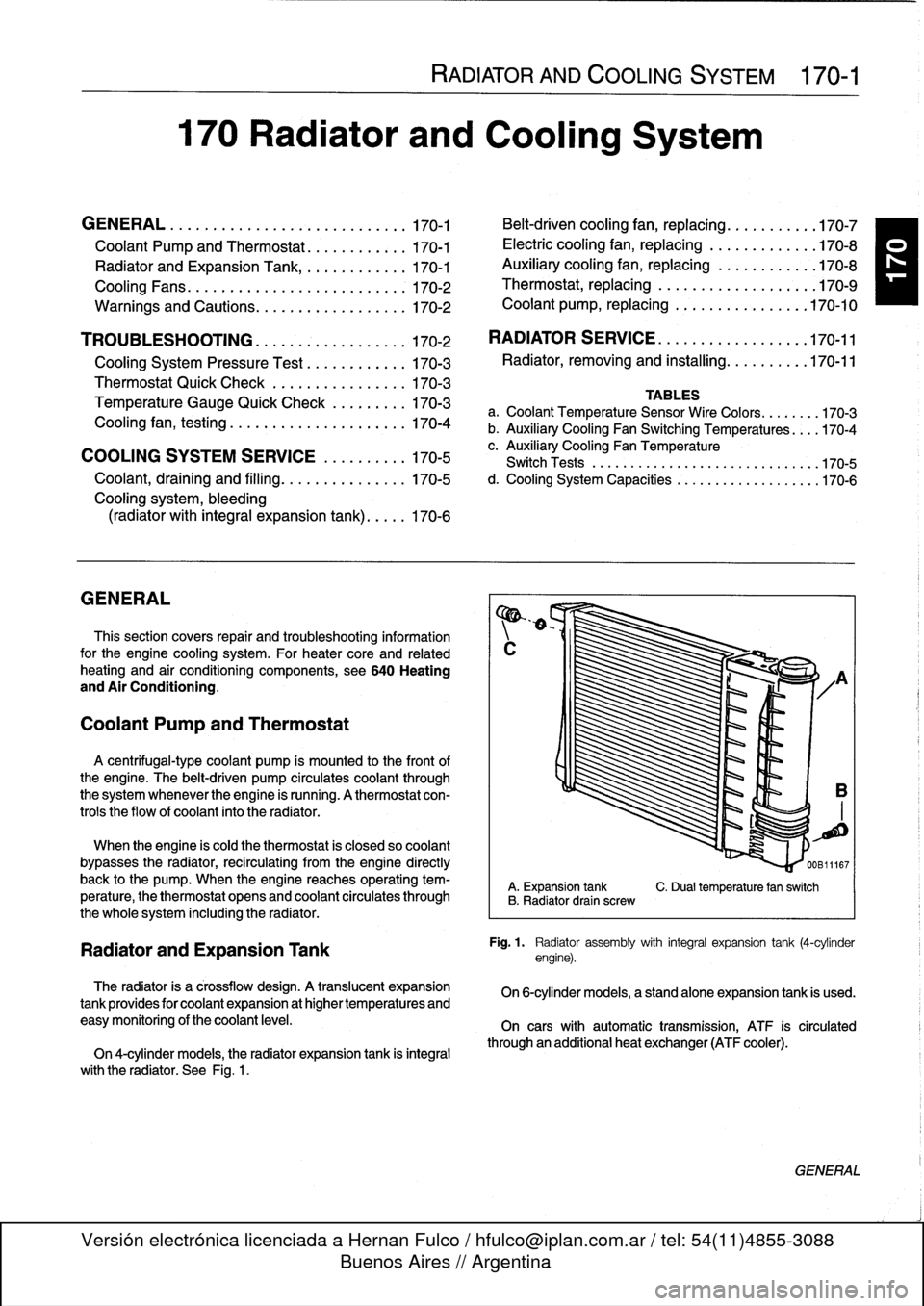
A
.
Expansion
tank
C
.
Dualtemperature
fan
switch
B
.
Radiator
drain
screw
Fig
.
1
.
Radiator
assembly
with
integral
expansion
tank
(4-cylinder
engine)
.
On
6-cylinder
models,
a
standalone
expansion
tank
is
used
.
On
cars
with
automatic
transmission,
ATF
is
circulated
through
an
additional
heat
exchanger
(ATF
cooler)
.
GENERAL
Page 197 of 759
Cooling
System
Pressure
Test
If
the
engine
overheats
and
no
other
cooling
system
testsindicate
trouble,
the
radiator
may
have
some
pluggedpassag-
A
cooling
system
pressure
test
is
used
to
check
for
internal
es
that
are
restricting
coolant
flow
.
leaks
.
Some
of
the
common
sources
ofinternal
leaks
are
a
faulty
cylinder
head
gasket,
a
cracked
cylinder
head,
or
a
Temperature
Gauge
Quick
Check
cracked
cylinder
block
.
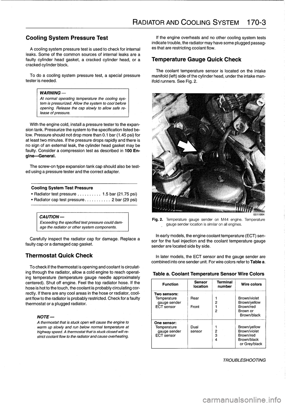
The
coolant
temperature
sensor
is
located
on
the
intake
To
doa
cooling
system
pressure
test,
a
special
pressure
manifold
(left)
side
of
the
cylinder
head,
under
the
intake
man-
tester
is
needed
.
ifold
runners
.
See
Fig
.
2
.
WARNING
-
At
normal
operating
temperature
-
the
cooling
sys-
tem
is
pressurized
.
Allow
the
system
to
cool
before
opening
.
Release
the
cap
slowly
to
allow
sale
re-
tease
of
pressure
.
With
the
engine
cold,instan
a
pressure
tester
to
the
expan-
sion
tank
.
Pressurize
thesystem
to
the
specification
listed
be-
low
.
Pressure
should
not
drop
more
than
0
.1
bar
(1
.45
psi)
for
at
leakt
two
minutes
.
If
the
pressure
drops
rapidly
and
there
is
no
sign
of
an
externa¡
leak,
the
cylinder
head
gasket
may
be
faulty
.
Considera
compression
test
as
described
in
100
En-
gine-General
.
The
screw-on
type
expansion
tank
cap
should
also
be
test-
ed
using
a
pressure
tester
and
the
correct
adapter
.
Cooling
System
Test
Pressure
"
Radiator
test
pressure
.........
.
1
.5
bar
(21
.75
psi)
"
Radiator
cap
test
pressure
..
.
........
2
bar
(29
psi)
CA
UTION-
Exceeding
the
speclfied
test
pressure
could
dam-
age
the
radiatoror
other
system
components
.
Carefully
inspect
the
radiator
cap
for
damage
.
Replace
a
faulty
cap
or
a
damaged
cap
gasket
.
Thermostat
Quick
Check
In
later
models,
the
ECT
sensor
and
the
gauge
sender
are
combined
into
one
sender
unit
.
For
wire
colors
refer
to
Table
a
.
To
check
if
the
thermostat
is
opening
and
coolant
is
circulat-
ing
through
the
radiator,
allow
a
cold
engine
to
reach
operat-
ing
temperature
(temperature
gauge
needieapproximately
centered)
.
Shut
off
engine
.
Feel
the
top
radiator
hose
.
If
the
hose
is
hot
to
the
touch,
the
coolant
is
probably
circulating
cor-
rectly
.
If
there
are
any
cool
areas
in
the
hose
or
radiator,
cool-
ant
flow
to
the
radiator
is
probably
restricted
.
Check
for
a
faulty
thermostat
or
aplugged
radiator
.
NOTE-
A
thermostat
that
is
stuck
open
will
cause
the
engine
to
warmup
slowly
and
run
belownormal
temperature
at
highway
speed
.
A
thermostat
that
is
stuck
closed
will
re-
strict
coolant
flow
to
the
radiator
and
cause
overheating
.
RADIATOR
AND
COOLING
SYSTEM
170-
3
U
.¡ig
.v
Fig
.
2
.
Temperature
gauge
sender
on
M44
engine
.
Temperature
gauge
sender
location
is
similar
on
al]
engines
.
In
early
models,
the
engine
coolant
temperature
(ECT)
sen-
sor
for
the
fuel
injection
and
the
coolant
temperature
gauge
sender
are
located
side
by
side
.
Table
a
.
Coolant
Temperature
Sensor
Wire
Colors
Function
Sensor
Terminal
Wire
colors
location
number
Two
sensors
:
Temperature
Rear
1
Brown/violet
gauge
sender
2
Brown/yellow
ECT
sensor
Front
1
Brown/red
2
Brown
or
Brown/black
One
sensor
:
Temperature
Dual
1
Brown/yellow
gauge
sender
sensor
2
Brown/violet
ECT
sensor
3
Brown/red
4
Brown/black
or
Grey/black
TROUBLESHOOTING
Page 198 of 759
170-
4
RADIATOR
AND
COOLING
SYSTEM
A
quick
testat
the
coolant
temperature
gauge
sender
can
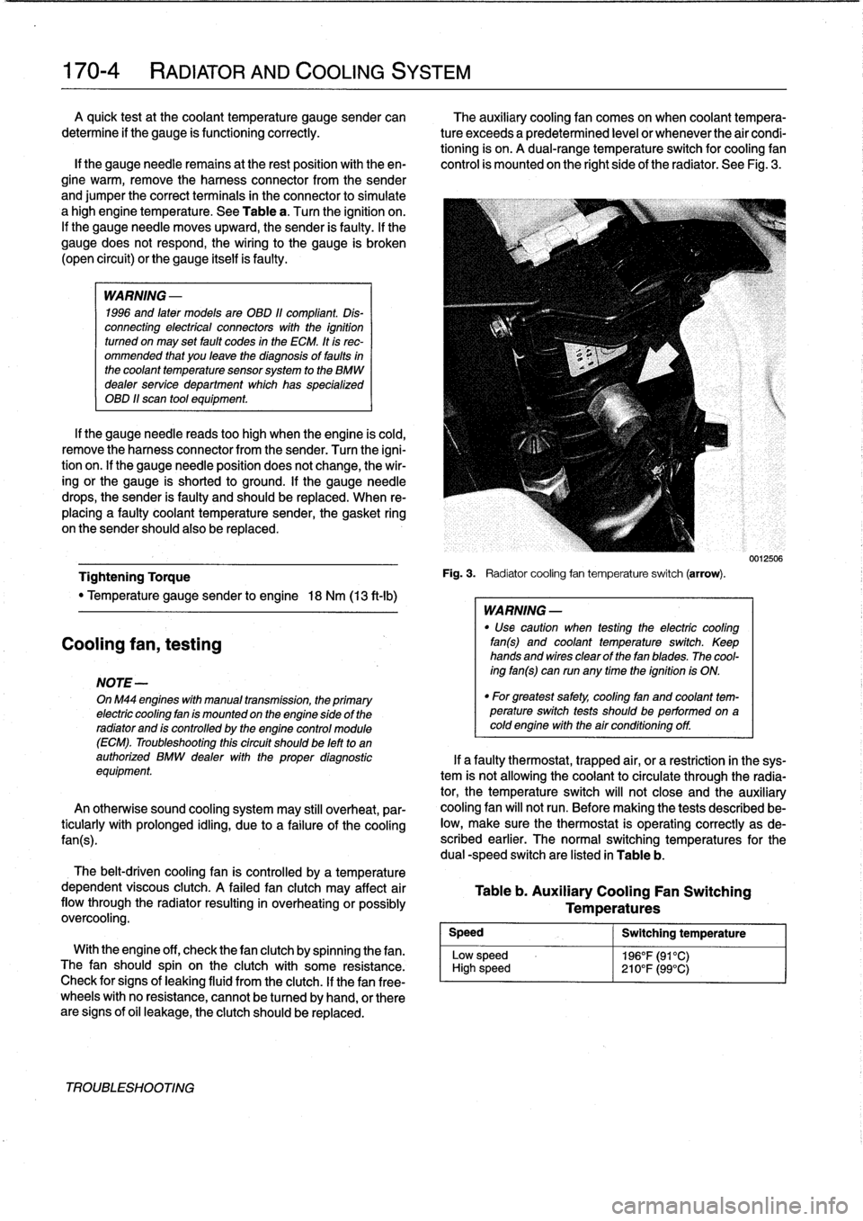
The
auxiliary
cooling
fan
comes
on
when
coolant
tempera
determine
if
the
gauge
is
functioning
correctly
.
ture
exceeds
a
predetermined
leve¡
or
whenever
the
air
condi-
tioning
is
on
.
A
dual-range
temperature
switch
for
cooling
fan
lf
the
gauge
needie
remains
at
the
rest
position
with
theen-
control
is
mounted
on
the
right
side
of
the
radiator
.
See
Fig
.
3
.
gine
warm,
remove
the
harness
connector
from
the
sender
and
jumper
the
correct
terminals
in
the
connector
to
simulate
a
high
engine
temperature
.
See
Table
a
.
Turn
the
ignition
on
.
If
the
gauge
needle
moves
upward,
the
sender
is
faulty
.
If
the
gauge
does
not
respond,
the
wiring
to
the
gauge
is
broken
(open
circuit)
or
the
gauge
itselfis
faulty
.
WARNING
-
1996
and
laten
models
are
OBD
11
compliant
.
Dis-
connecting
electrical
connectors
wíth
the
ignition
turned
on
may
set
fault
codes
in
the
ECM
.
It
is
rec-
ommended
that
you
leave
the
diagnosis
of
faults
in
the
coolant
temperature
sensorsystem
to
the
BMW
dealer
service
department
which
has
specialized
OBD
11
scan
tool
equipment
.
If
the
gauge
needle
reads
too
high
when
the
engine
is
cold,
remove
the
harness
connector
from
the
sender
.
Turn
the
igni-
tion
on
.
lf
the
gauge
needle
position
does
not
change,
the
wir-
ing
or
the
gauge
is
shorted
to
ground
.
If
the
gauge
needle
drops,
the
sender
is
faulty
and
should
be
replaced
.
When
re-
placing
a
faulty
coolant
temperature
sender,
the
gasket
ring
on
the
sender
should
also
be
replaced
.
Tightening
Torque
"
Temperature
gauge
sender
to
engine
18
Nm
(13
ft-Ib)
Cooling
fan,
testing
NOTE-
OnM44
engines
with
manual
transmission,
the
primary
electric
cooling
fan
is
mounted
on
the
engine
side
of
the
radiator
and
is
controlled
by
the
engine
control
module
(ECM)
.
Troubleshooting
thiscircuit
should
be
left
to
an
authorized
BMW
dealer
with
the
proper
diagnostic
equipment
An
otherwise
sound
cooling
system
may
still
overheat,
par-
ticularly
with
prolonged
idling,
due
to
a
failure
of
the
coolíng
fan(s)
.
The
belt-driven
cooling
fan
is
controlled
by
a
temperature
dependent
viscous
clutch
.
A
failed
fan
clutch
may
affect
air
flow
through
the
radiator
resulting
in
overheating
orpossibly
overcooling
.
Speed
Low
sp
High
s
With
the
engine
off,
check
thefan
clutch
by
spinning
thefan
.
eed
The
fan
should
spin
on
the
clutch
with
some
resistance
.
peed
Check
for
signs
of
leaking
fluid
from
the
clutch
.
If
thefan
free-
wheels
with
no
resistance,
cannot
be
tu
rned
by
hand,
or
there
are
signs
of
oil
leakage,
the
clutch
should
be
replaced
.
TROUBLESHOOTING
Fig
.
3
.
Radiatorcooling
fan
temperature
switch
(arrow)
.
WARNING
-
"
Use
caution
when
testing
the
electric
cooling
fan(s)
and
coolant
temperature
switch
.
Keep
hands
and
wires
clear
of
thefan
blades
.
The
cool-
ing
fan(s)
can
run
any
time
the
ignition
is
ON
.
"
For
greatest
safety,
coolíng
fan
and
coolant
tem-perature
switch
tests
shouldbe
performed
on
acoldengine
with
the
air
conditioning
off
.
Table
b
.
Auxiliary
Cooling
Fan
Switching
Temperatures
Switching
temperature
196°F(91°C)
210°F(99°C)
0012506
If
a
faulty
thermostat,
trapped
air,
or
a
restriction
in
the
sys-
tem
is
not
allowing
the
coolant
to
circulate
through
the
radia-
tor,
the
temperature
switch
will
not
close
and
the
auxiliary
cooling
fan
will
not
run
.
Before
making
the
tests
described
be-
low,
make
sure
the
thermostat
is
operating
correctly
as
de-
scribed
earlier
.
The
normal
switching
temperatures
for
the
dual
-speed
switch
are
listed
in
Table
b
.
Page 205 of 759
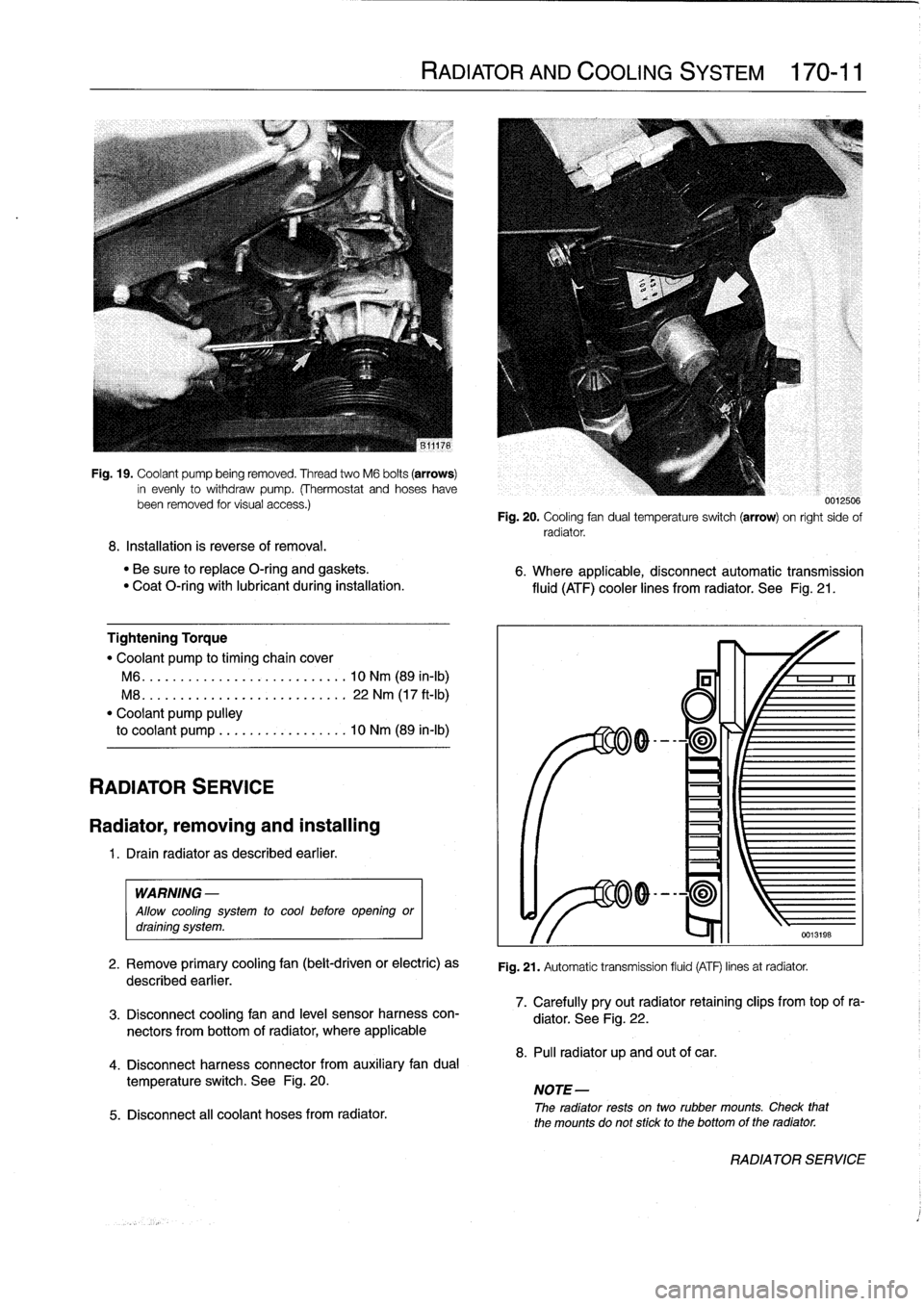
Fig
.
19
.
Coolant
pump
being
removed
.
Thread
two
M6
bolts
(arrows)
in
evenly
to
withdraw
pump
.
(Thermostat
and
hoseshavebeen
removed
tor
visual
access
.)
8
.
Installation
is
reverse
of
removal
.
"
Be
sure
to
replace
O-ring
and
gaskets
.
"
Coat
O-ring
with
lubricant
during
installation
.
Tightening
Torque
"
Coolant
pump
to
timing
chaincover
M6
...
.
...................
..
.
.
10
Nm
(89
in-lb)
M8
.
..
.
....................
.
.
.
22
Nm
(17
ft-Ib)
"
Coolant
pump
pulley
to
coolant
pump
.................
10
Nm
(89
in-lb)
RADIATOR
SERVICE
Radiator,
removing
and
installing
1
.
Drain
radiator
as
described
earlier
.
WARNING
-
Allow
cooling
system
to
cool
before
opening
ordraining
system
.
2
.
Remove
primary
cooling
fan
(belt-driven
or
electric)
as
described
earlier
.
3
.
Disconnect
coolingfan
and
leve¡
sensor
harness
con-
nectors
from
bottom
of
radiator,
where
applicable
4
.
Disconnect
harness
connector
from
auxiliary
fandual
temperature
switch
.
See
Fig
.
20
.
5
.
Disconnect
all
coolant
hoses
from
radiator
.
RADIATOR
AND
COOLING
SYSTEM
170-11
0012500
Fig
.
20
.
Cooling
fan
dual
temperatura
switch
(arrow)
on
right
sido
of
radiator
.
6
.
Where
applicable,
disconnectautomatic
transmission
fluid
(ATF)
cooler
lines
from
radiator
.
See
Fig
.
21
.
Fig
.
21
.
Automatic
transmission
fluid
(ATF)
linos
at
radiator
.
7
.
Carefully
pryout
radiator
retaining
clips
from
top
of
ra-
diator
.
See
Fig
.
22
.
8
.
Pul¡
radiator
up
and
out
of
car
.
NOTE-
The
radiator
rests
ontwo
rubber
mounts
.
Check
that
the
mounts
do
not
stick
to
the
bottomof
the
radiator
.
RADIATOR
SERVICE
Page 393 of 759
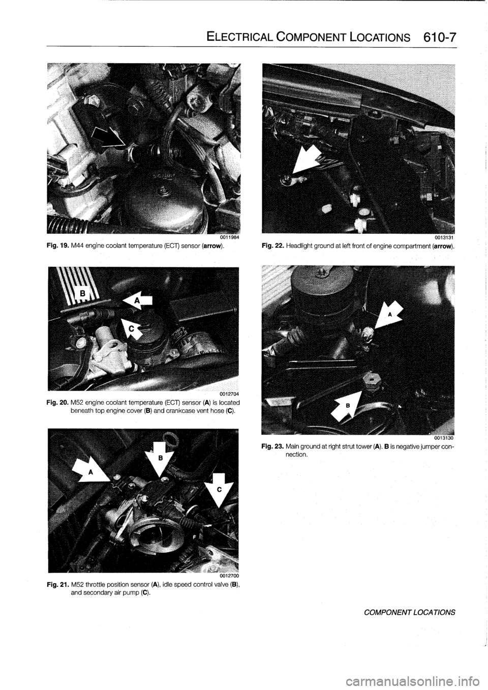
Fig
.
19
.
M44
engine
coolant
temperature
(ECT)
sensor
(arrow)
.
Fig
.
22
.
Headlight
ground
at
left
frontof
engine
compartment
(arrow)
.
0012704
Fig
.
20
.
M52
engine
coolant
temperature
(ECT)
sensor
(A)
is
located
beneath
top
enginecover
(B)
and
crankcase
vent
hose
(C)
.
uu12700
Fig
.
21
.
M52
throttle
position
sensor
(A),
idle
speed
control
valve
(B),
and
secondary
air
pump
(C)
.
ELECTRICAL
COMPONENT
LOCATIONS
610-7
00119s4
0013131
uvijijo
Fig
.
23
.
Mainground
at
right
strut
tower
(A)
.
B
is
negative
jumper
con-
nection
.
COMPONENT
LOCA
TIONS
Page 398 of 759
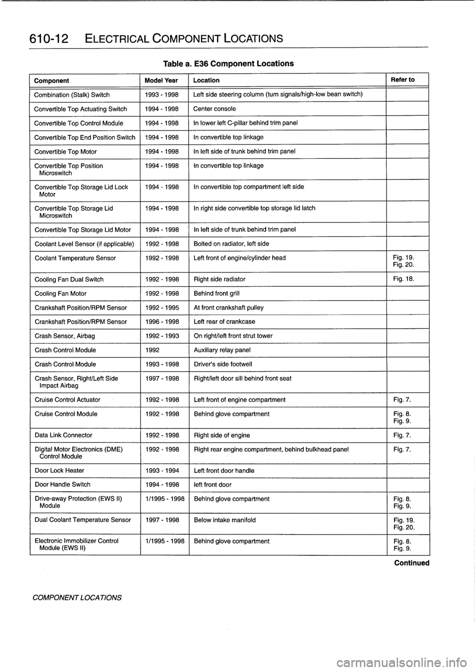
610-12
ELECTRICAL
COMPONENT
LOCATIONS
Table
a
.
E36
Component
Locations
Component
Model
Year
Location
Refer
to
Combination
(Stalk)
Switch
1993-1998
Left
sidesteering
column
(turn
signals/high-low
bean
switch)
Convertible
Top
ActuatingSwitch
1994-1998
Center
console
Convertible
Top
Control
Module
1994-1998
In
lower
left
C-pillar
behind
trim
panel
Convertible
TopEnd
Position
Switch
1994-1998
In
convertible
top
linkage
Convertible
Top
Motor
1994-1998
In
left
sideof
trunk
behind
trim
panel
Convertible
Top
Position
1994-1998
In
convertible
top
linkage
Microswitch
Convertible
Top
Storage
Lid
Lock
1994-1998
In
convertible
top
compartment
left
side
Motor
Convertible
Top
Storage
Lid
1994-1998
Inright
side
convertible
top
storage
lid
latch
Microswitch
Convertible
Top
Storage
Lid
Motor
1994-1998
In
left
side
of
trunk
behind
trim
panel
Coolant
Leve¡
Sensor
(if
applicable)
1992-1998
Bolted
on
radiator,
left
side
Coolant
Temperature
Sensor
1992-1998
Left
front
of
engine/cylinder
head
Fig
.
19
.
Fig
.
20
.
Cooling
Fan
Dual
Switch
1992-1998
Right
side
radiator
Fig
.
18
.
Cooling
Fan
Motor
1992-1998
Behind
front
grill
Crankshaft
Position/RPM
Sensor
1992-1995
At
front
crankshaft
pulley
Crankshaft
Position/RPM
Sensor
1996-1998
Left
rearof
crankcase
Crash
Sensor,
Airbag
1992-1993
On
right/left
frontstrut
tower
Crash
Control
Module
1992
Auxiliary
relay
panel
Crash
Control
Module
1993-1998
Driver's
side
footwell
Crash
Sensor,
Right/Left
Side
1997-1998
Right/left
door
sill
behind
front
seat
Impact
Airbag
Cruise
Control
Actuator
1992-1998
Left
front
of
engine
compartment
Fig
.
7
.
Cruise
Control
Module
1992-1998
Behind
glove
compartment
Fig
.
8
.
Fig
.
9
.
Data
Link
Connector
1992-1998
Right
sideof
engine
Fig
.
7
.
Digital
Motor
Electronics
(DME)
1992-1998
Right
rear
engine
compartment,
behind
bulkhead
panel
Fig
.
7
.
Control
Module
DoorLock
Heater
1993-1994
Left
front
doorhandle
DoorHandle
Switch
1994-1998
left
front
door
Drive-away
Protection
(EWS
II)
1/1995
-
1998
Behind
glove
compartment
Fig
.
8
.
Module
Fig
.
9
.
Dual
Coolant
Temperature
Sensor
1997-1998
Below
intake
manifold
Fig
.
19
.
COMPONENT
LOCATIONS
Fig
.
20
.
Electronic
Immobilizer
Control
(
1/1995-1998
~
Behind
glove
compartment
Fig
.
8
.
Module
(EWS
II)
Fig
.
9
.
Continued
Page 399 of 759
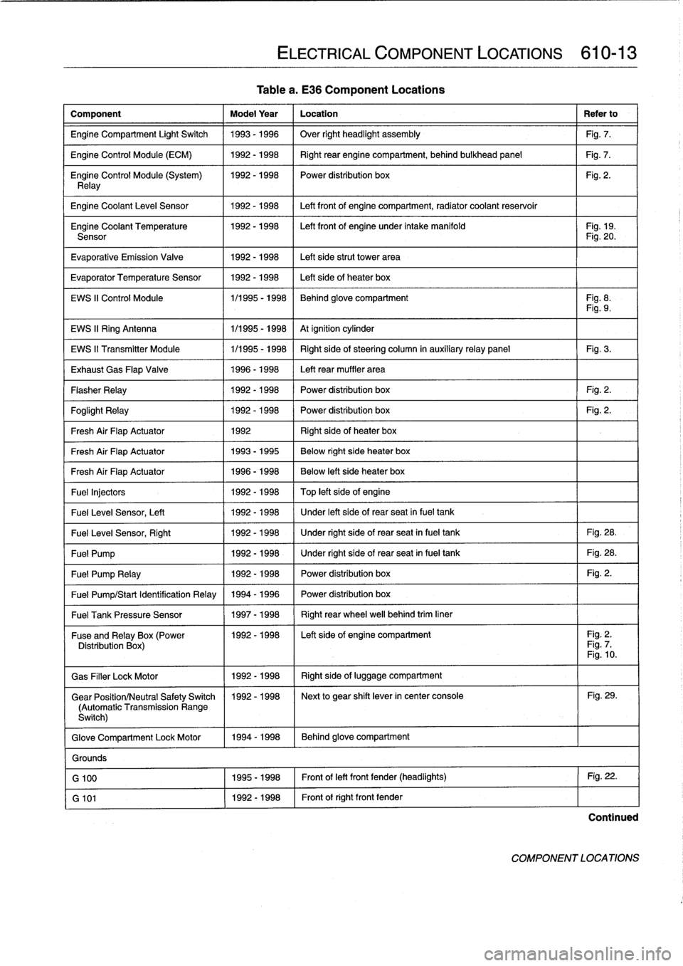
Tablea
.
E36
Component
Locations
Component
Model
Year
Location
Refer
to
Engine
Compartment
Light
Switch
1993-1996
Over
right
headlight
assembly
Fig
.
7
.
Engine
Control
Module
(ECM)
1992-1998
Right
rear
enginecompartment,
behind
bulkhead
panel
Fig
.
7
.
Engine
Control
Module
(System)
1992-1998
I
Power
distribution
box
Fig
.
2
.
Relay
Engine
Coolant
Leve¡
Sensor
1
1992-1998
1
Left
front
of
enginecompartment,
radiator
coolant
reservoir
Engine
Coolant
Temperature
1992-1998
I
Left
front
of
engine
under
intake
manifold
I
Fig
.
19
.
Sensor
Fig
.
20
.
Evaporative
Emission
Valve
1992-1998
Left
side
strut
Power
area
Evaporator
Temperature
Sensor
1992-1998
Left
side
of
heater
box
EWS
II
Control
Module
1/1995
-
1998
Behind
glove
compartment
Fig
.
8
.
Fig
.
9
.
EWS
II
Ring
Antenna
1
1/1995
-
1998
1
At
ignition
cylinder
EWS
II
Transmitter
Module
1/1995
-
1998
Right
side
of
steering
column
in
auxiliaryrelay
panel
Fig
.
3
.
Exhaust
Gas
Flap
Valve
1996-1998
Left
rear
muffler
area
Flasher
Relay
1992-1998
Power
distribution
box
Fig
.
2
.
Foglight
Relay
1
1992-1998
1
Power
distribution
box
1
Fig
.
2
.
Fresh
Air
FlapActuator
1
1992
1
Right
side
of
heater
box
Fresh
Air
FlapActuator
1
1993-1995
1
Below
right
side
heater
box
Fresh
Air
FlapActuator
1
1996-1998
Below
left
side
heater
box
Fuel
Injectors
1992
-
1998
Top
left
side
of
engine
Fuel
Leve¡
Sensor,
Left
1
1992-1998
/
Under
left
side
of
rear
seat
infuel
tank
Fuel
Leve¡
Sensor,
Right
1
1992-1998
1
Under
right
side
of
rear
seat
in
fuel
tank
1
Fig
.
28
.
Fuel
Pump
1
1992-1998
1
Under
right
side
of
rear
seat
in
fuel
tank
1
Fig
.
28
.
Fuel
Pump
Relay
1
1992-1998
1
Power
distribution
box
1
Fig
.
2
.
Fuel
Pump/Start
Identification
Relay
1994
-
1996
Power
distribution
box
Fuel
Tank
Pressure
Sensor
1
1997-1998
1
Right
rear
wheel
well
behind
trim
liner
ELECTRICAL
COMPONENT
LOCATIONS
610-13
Fuse
andRelay
x(Power
11992-1998
I
Left
side
of
engine
compartment
I
Fig
.
2
.
Distribution
Box
Fig
.
7
Fig
.
10
.
Gas
Filler
LockMotor
1992-1998
Right
side
of
luggage
compartment
Gear
Position/Neutral
Safety
Switch
1992-1998
Next
to
gear
shift
lever
in
center
console
Fig
.
29
.
(Automatic
Transmission
Range
Switch)
Glove
Compartment
Lock
Motor
1994-1998
Behind
glove
compartment
Grounds
G
100
1995-1998
Front
of
left
front
fender
(headlights)
Fig
.
22
.
G
101
1992-1998
Front
of
right
front
fender
Continued
COMPONENT
LOCATIONS
Page 450 of 759
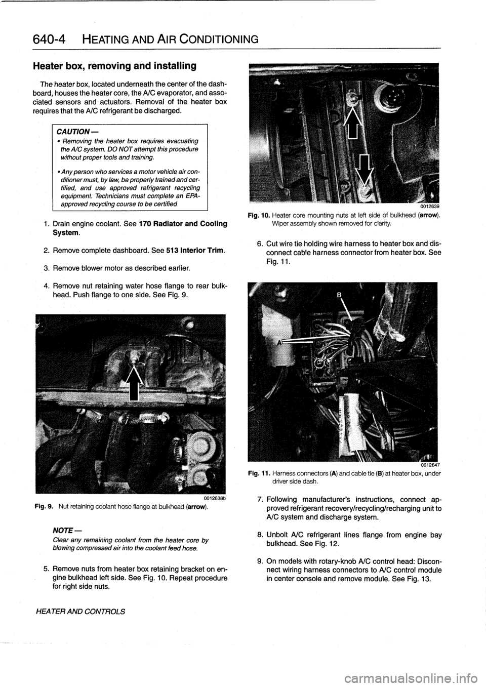
640-4
HEATING
AND
AIR
CONDITIONING
Heater
box,
removing
and
installing
The
heater
box,
located
underneath
thecenter
of
the
dash-
board,
houses
theheater
core,
the
A/C
evaporator,
and
asso-
ciated
sensors
and
actuators
.
Removal
of
theheater
box
requires
that
the
A/C
refrigerant
be
discharged
.
CAUTION-
"
Removing
the
heater
box
requires
evacuating
the
AIC
system
.
DO
NOT
attempt
this
procedure
without
proper
tools
and
training
.
"
Any
person
who
services
a
motor
vehicle
air
con-
ditioner
must,
by
law,
be
properly
trained
and
cer-
tified,
and
use
approved
refrigerant
recycling
equipment
.
Technicians
must
complete
an
EPA-
approved
recycling
course
to
be
certified
UU12639
Fig
.
10
.
Heater
core
mounting
nuts
at
left
sideof
bulkhead
(arrow)
.
1
.
Drain
engine
coolant
.
See
170
Radiator
and
Cooling
wiper
assembly
shown
removed
for
clarity
.
System
.
2
.
Remove
complete
dashboard
.
See513
Interior
Trim
.
3
.
Remove
blower
motoras
described
earlier
.
4
.
Remove
nut
retaining
water
hose
flange
to
rear
bulk-
head
.
I'ush
flange
to
one
side
.
See
Fig
.
9
.
Fig
.
9
.
Nut
retaining
coolant
hose
flangeat
bulkhead
(arrow)
.
NOTE-
Clear
any
remaining
coolant
from
the
heater
core
by
blowing
compressed
air
finto
the
coolant
feed
hose
.
HEATER
AND
CONTROLS
0012638b
6
.
Cut
wire
tie
holding
wire
harness
to
heater
box
and
dis-
connect
cable
harness
connector
from
heater
box
.
See
Fig
.
11
.
0012647
Fig
.
11
.
Harness
connectors
(A)
and
cable
tie
(B)
at
heaterbox,
under
driver
side
dash
.
7
.
Followingmanufacturer's
instructions,
connect
ap-
proved
refrigerant
recovery/recycling/recharging
unitto
A/C
system
and
discharge
system
.
8
.
Unbolt
A/C
refrigerantlines
flange
from
engine
bay
bulkhead
.
See
Fig
.
12
.
9
.
On
models
with
rotary-knob
A/C
control
head
:
Discon-
5
.
Remove
nuts
from
heater
box
retaining
bracket
on
en-
nect
wiring
harness
connectors
to
A/C
control
module
gine
bulkhead
left
side
.
See
Fig
.
10
.
Repeat
procedure
in
center
console
and
remove
module
.
See
Fig
.
13
.
for
right
side
nuts
.
Page 452 of 759
640-6
HEATING
AND
AIRCONDITIONING
Heater
core,replacing
1.
Drain
engíne
coolant
.
See170
Radiator
and
Cooling
System
.
WARNING
-
Allow
the
cooling
system
to
cool
before
opening
or
drainíng
the
cooling
system
.
2
.
Remove
center
console
.
See
513
Interior
Trim
.
3
.
Remove
Multi-Information
Display
(MID)
module
.
See
620
Instruments
.
4
.
Remove
lower
dash
panel
and
knee
bolster
on
driver
side
.
See
513
Interior
Trim
.
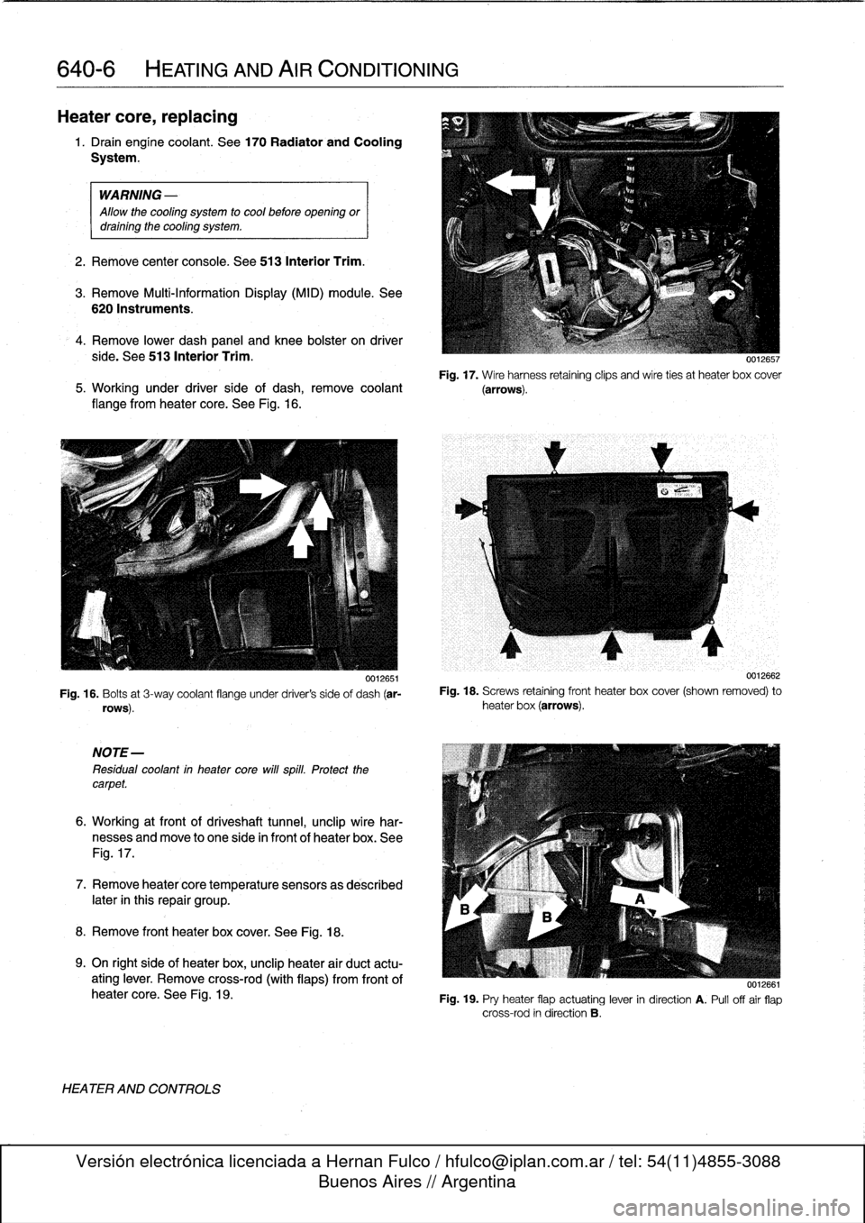
Fig
.
17
.
Wire
harness
retaining
clips
and
wire
ties
at
heater
box
cover
5
.
Working
under
driver
side
of
dash,
remove
coolant
(arrows)
.
flange
from
heater
core
.
See
Fig
.
16
.
0012651
Fig
.
16
.
Bolts
at
3-way
coolant
flange
under
driver's
side
of
dash
(ar-
rows)
.
NOTE-
Residual
coolant
in
heater
core
will
spill
.
Protect
thecarpet
.
6
.
Working
at
front
of
driveshaft
tunnel,
unclip
wire
har-
nesses
and
move
to
one
side
in
front
of
heater
box
.
See
Fig
.
17
.
7
.
Remove
heatercore
temperature
sensorsas
described
later
in
this
repair
group
.
8
.
Remove
front
heater
box
cover
.
See
Fig
.
18
.
9
.
On
right
side
of
heater
box,
unclip
heater
air
duct
actu-
ating
lever
.
Remove
cross-rod
(with
flaps)
from
frontof
heater
core
.
See
Fig
.
19
.
HEATER
AND
CONTROLS
0012662
Fig
.
18
.
Screws
retaining
front
heater
box
cover
(shown
removed)
to
heater
box
(arrows)
.
0012661
Fig
.
19
.
Pry
heater
flap
actuating
lever
in
direction
A
.
Pull
offair
flap
cross-rod
in
direction
B
.