diff BMW M3 1998 E36 Owner's Manual
[x] Cancel search | Manufacturer: BMW, Model Year: 1998, Model line: M3, Model: BMW M3 1998 E36Pages: 759
Page 149 of 759
FUEL
INJECTION
130-
3
Fuel
metering
.
The
ECM
meters
fuel
bychanging
the
The
engine
management
system
compensates
automatical-
opening
time
(pulsewidth)
of
the
fuel
injectors
.
To
ensure
that
ly
for
changes
in
the
engine
due
to
age,
minor
wear
or
small
injector
pulsewídth
is
the
only
factor
that
determines
fuel
me-
problems,
such
as
a
disconnected
vacuum
hose
.
Asa
result,
tering,fuel
pressure
is
maintained
bya
fuel
pressure
regula-
idle
speed
and
mixture
do
not
need
lo
be
adjustedas
partof
tor
.
The
injectors
are
mounted
lo
a
common
fuel
supply
called
routine
maintenance
.
the
fuel
rail
.
The
ECM
monitors
engine
speed
to
determine
the
duration
NOTE-
ofinjector
openings
.
Other
signals
to
the
ECM
help
determine
Poordriveabilitymaybe
encountered
when
the
batteryis
injector
pulse
time
for
different
operating
conditions
.
A
tem-
disconnected
and
reconnected
.
when
the
battery
is
dis-
connected,
the
adaptive
memory
is
lost
The
system
will
perature
sensor
signals
engine
temperature
for
mixture
adap-
readaptafterabout
ten
minutes
of
drfving
.
tion
.
A
throttle
position
sensor
signals
throttle
position
.
The
exhaust
oxygen
sensor(s)
signal
information
about
combus-
tion
efficiency
for
control
of
the
air-fuel
mixture
.
1992
to
1995
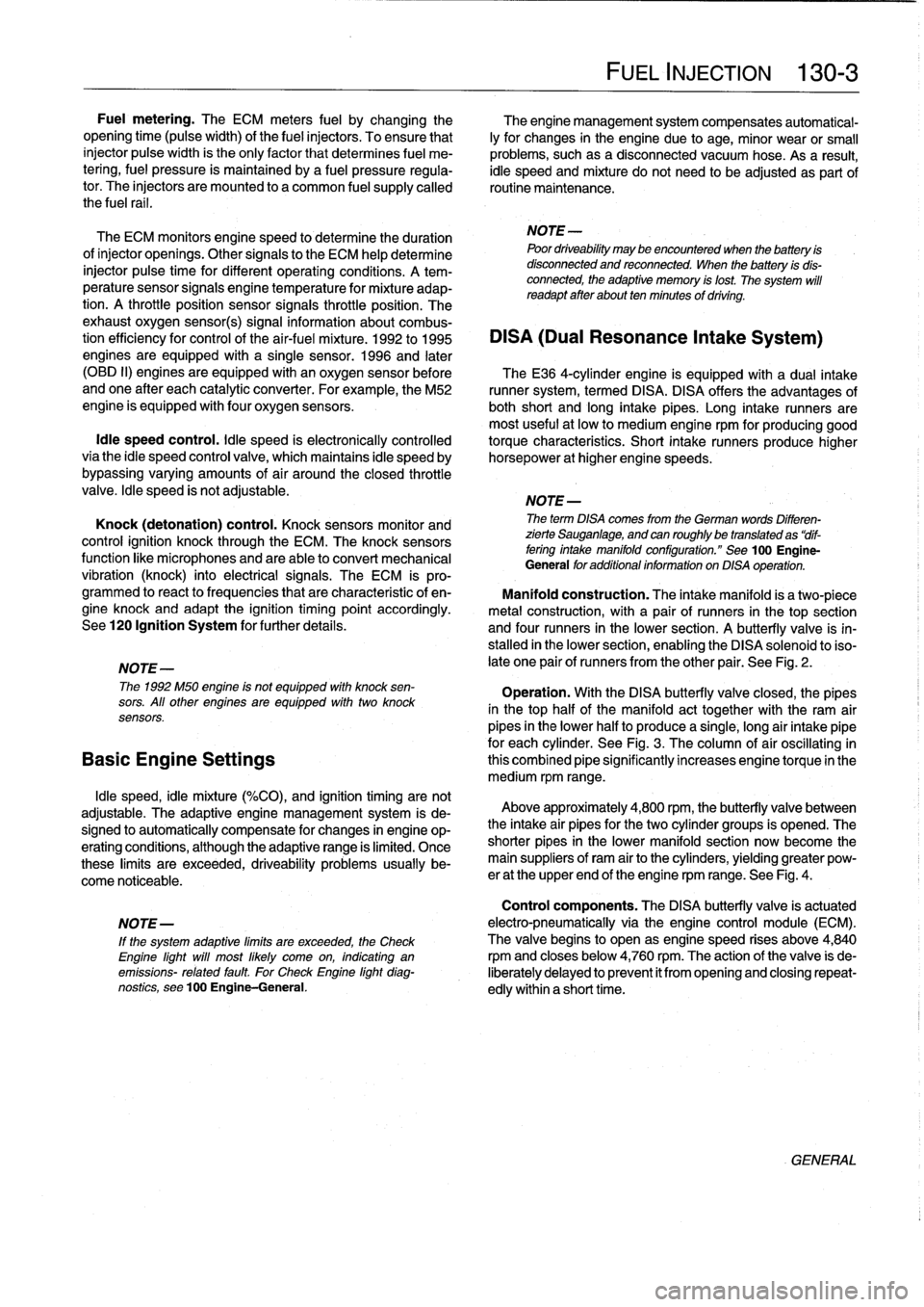
DISA
(Dual
Resonance
Intake
System)
engines
are
equipped
with
a
single
sensor
.
1996
and
later
(OBD
II)
engines
are
equipped
with
an
oxygen
sensor
before
TheE36
4-cylinder
engine
is
equipped
with
a
dual
intake
andone
after
each
catalytic
converter
.
Forexample,the
M52
runner
system,
termed
DISA
.
DISA
offers
the
advantages
of
engine
is
equipped
withfour
oxygen
sensors
.
both
short
and
long
intake
pipes
.
Long
intake
runners
are
most
useful
at
low
to
medium
engine
rpm
for
producing
good
Idle
speed
control
.
ldle
speed
is
electronically
controlled
torque
characteristics
.
Short
intake
runners
produce
hígherviathe
idle
speed
control
valve,
which
maintains
idle
speed
by
horsepower
at
hígher
engine
speeds
.
bypassing
varying
amounts
of
air
around
theclosed
throttle
valve
.
Idle
speed
is
not
adjustable
.
NOTE-
Knock
(detonation)
control
.
Knock
sensors
monitor
and
The
term
DISA
comes
from
the
German
words
Differen-
control
ignition
knock
through
the
ECM
.
The
knock
sensors
zierte
Sauganlage,
and
can
roughlybe
translated
as
"dif-
fering
intake
manifold
configuration
."
See
100
Engine-
function
like
microphones
and
are
able
to
convert
mechanical
General
foradditional
information
on
DISA
operation
.
vibration
(knock)
into
electrical
signals
.
The
ECM
is
pro-
grammed
to
react
to
frequencies
that
are
characteristic
of
en-
Manifold
construction
:
The
intake
manifold
is
a
two-piece
gine
knock
and
adapt
the
ignition
timing
point
accordingly
.
metal
construction,
with
a
pair
of
runners
in
thetop
section
See120
Ignition
System
for
further
details
.
and
four
runners
in
the
lower
section
.
A
butterfly
valve
is
in-
stalled
in
the
lower
section,
enabling
the
DISA
solenoid
toiso-
NOTE-
late
one
pair
of
runners
from
the
other
pair
.
See
Fig
.
2
.
The
1992
M50
engine
is
not
equipped
with
knock
sen-
Operation
.
With
the
DISA
butterfly
valve
closed,
the
pipes
sors
.
All
other
engines
are
equipped
with
two
knock
in
thetop
half
of
the
manifold
act
together
with
the
ram
air
sensors
.
pipes
in
the
lower
halfto
producea
single,
long
air
intake
pipe
for
each
cylinder
.
See
Fig
.
3
.
The
column
of
aír
oscíllating
in
Basic
Engine
Settings
this
combined
pipe
significantly
increases
engine
torque
in
the
medium
rpm
range
.
Idle
speed,
idle
mixture
(%CO),
and
ignition
timing
arenot
adjustable
.
The
adaptive
engine
management
system
is
de-
signed
to
automatically
compensate
for
changes
in
engine
op-
eratingconditions,
although
the
adaptive
range
is
limited
.
Once
these
limits
are
exceeded,
driveability
problems
usually
be-
come
noticeable
.
Above
approximately
4,800
rpm,
the
butterfly
valve
between
the
intake
air
pipes
for
the
two
cylinder
groups
is
opened
.
The
shorter
pipes
in
the
lower
manifold
section
now
become
the
main
suppliers
of
ram
air
to
the
cylinders,yielding
greater
pow-
er
at
the
upper
end
of
the
engine
rpm
range
.
See
Fig
.
4
.
Control
components
.
The
DISA
butterfly
valve
is
actuated
NOTE-
electro-pneumatically
via
the
engine
control
module
(ECM)
.
lf
the
system
adaptive
limits
are
exceeded,
the
Check
The
valve
begins
to
open
as
engine
speed
rises
aboye
4,840
Engine
light
will
most
likely
come
on,
indicating
an
rpmand
closes
below
4,760
rpm
.
The
action
of
the
valve
is
de-
emissions-
related
fault
For
Check
Engine
light
diag-
liberately
delayed
to
prevent
it
from
opening
and
closing
repeat-
nostics,
see100
Engine-General
.
edly
within
a
short
time
.
GENERAL
Page 150 of 759
130-
4
FUEL
INJECTION
Main
Relay
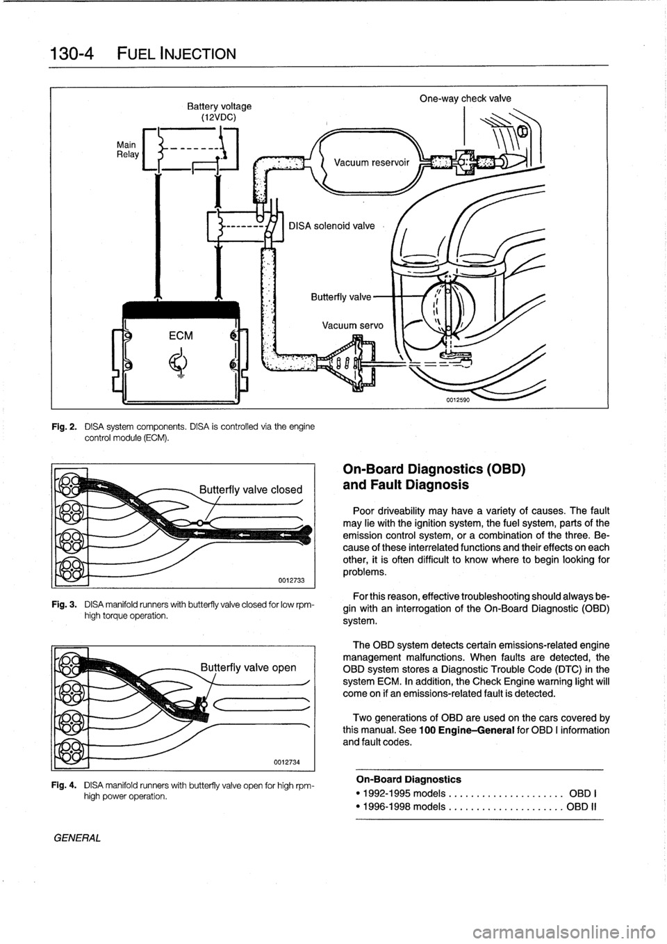
Fig
.
2
.
DISA
system
components
.
DISA
is
controlled
via
theengine
control
module
(ECM)
.
Fig
.
3
.
DISA
manifold
runners
with
butterfly
valve
closed
for
lowrpm-
high
torque
operation
.
yje
q
GENERAL
high
power
operation
.
0012734
Fig
.
4
.
DISA
manifold
runners
with
butterfly
valve
open
for
high
rpm-
On-Board
Diagnostics
(OBD)
and
Fault
Diagnosis
Poor
driveability
may
have
a
variety
of
causes
.
The
fault
may
He
withthe
ignition
system,
the
fuel
system,
parts
ofthe
emission
control
system,
ora
combination
of
thethree
.
Be-
cause
of
these
interrelated
functions
and
their
effects
on
each
other,
it
is
often
difficult
to
know
where
to
begin
looking
for
problems
.
For
this
reason,
effective
troubleshooting
should
always
be-
gin
with
an
interrogation
of
the
On-Board
Diagnostic
(01313)
system
.
The
OBD
system
detects
certain
emissions-related
engine
management
malfunctions
.
When
faults
are
detected,the
OBD
system
storesa
Diagnostic
Trouble
Code
(DTC)
in
the
system
ECM
.
In
addition,
the
Check
Engine
warning
light
will
come
on
if
an
emissions-related
fault
is
detected
.
Two
generations
of
OBD
are
used
on
thecars
covered
by
this
manual
.
See
100
Engine-General
for
OBD
I
information
and
fault
codes
.
On-Board
Diagnostics
"
1992-1995models
....
.
...
...
.
...
......
OBD
I
"
1996-1998models
....
.
..
.
.
.
..
...
......
OBD
II
Page 163 of 759
BOSCH
DME
MM
AND
M33
.1
COMPONENT
TESTS
AND
REPAIRS
Consult
Table
a
for
engine
application
information
for
the
Bosch
DME
3
.1
and
3
.3.1
systems
.
The
DME
3
.1
and
DME
3
.3
.1
systems
are
similar
in
opera-
tion,
with
knock
control
and
VANOS
operation
being
the
key
differences
.
DME
3
.1
engines
arenot
equipped
with
VANOS
or
knock
detectors,
while
the
DM
E3
.3
.1
system
is
.
CA
UTION-
Use
onty
a
digital
multimeter
when
testing
wiring
.
Use
of
an
analog
VOM
may
damage
the
engine
control
module
.
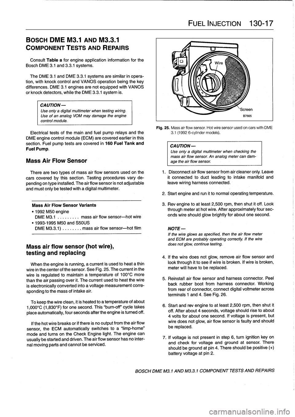
Fig
.
25
.
Mass
air
flow
sensor
.
Hot
wire
sensor
usedon
carswith
DME
Electrical
tests
of
the
main
and
fuel
pump
relays
and
the
3
.1
(1992
6-cylinder
models)
.
DME
engine
control
module
(ECM)
are
covered
earlier
in
this
section
.
Fuel
pump
tests
are
covered
in
160
Fuel
Tank
and
CAUTION-
Fuel
Pump
.
Use
only
a
digital
multimeter
when
checking
the
mass
air
flow
sensor
.
An
analog
meter
can
dam-
Mass
Air
Flow
Sensor
age
theair
flow
sensor
.
There
are
two
types
of
mass
air
flow
sensors
used
onthe
1
.
Disconnect
air
flow
sensor
from
air
cleaner
only
.
Leave
cars
covered
by
this
section
.
Testing
procedures
vary
de-
it
connected
to
duct
leading
to
intake
manifold
and
pending
on
type
installed
.
The
airflow
sensor
is
not
adjustable
leave
wiring
harness
connected
.
and
must
only
be
tested
with
a
digital
multimeter
.
Mass
Air
FlowSensor
Variants
"
1992
M50
engine
DME
M3
.1
.
.
.
.
...
..
mass
air
flow
sensor-hot
wire
"
1993-1995
M50
and
S50US
DMEM33
.1)
.
...
...
.
mass
air
flow
sensor-hot
film
Mass
air
flow
sensor
(hot
wire),
testing
and
replacing
When
the
engine
is
running,
a
current
is
used
to
heat
a
thin
wire
in
the
center
of
the
sensor
.
See
Fig
.
25
.
The
current
in
the
wire
is
regulated
to
maintain
a
temperature
of
100°C
more
than
the
air
passing
over
it
.
The
current
used
to
heat
the
wire
is
electronically
conneced
into
a
voltage
measurement
corre-
sponding
to
the
mass
of
intake
a¡
r
.
To
keep
the
wire
clean,
it
is
heated
to
a
temperature
of
about
1,000°C
(1,830°F)
for
one
second
.
This
"burn-off"
cycle
takes
place
automatically,
four
seconds
after
the
engine
is
tumed
off
.
lf
thehot
wire
breaks
or
if
there
is
no
output
from
the
air
flow
sensor,
the
ECM
automatically
switches
to
a
"limp-home"
mode
and
tucos
on
the
Check
Engine
light
.
The
engine
can
usually
be
started
and
driven
.
The
air
flow
sensor
has
no
inter-
nal
moving
parts
and
cannot
be
serviced
.
FUEL
INJECTION
130-
1
7
2
.
Start
engine
and
run
it
to
normal
operating
temperature
.
3
.
Rev
engine
toat
least
2,500
rpm,then
shut
it
off
.
Look
through
meter
at
hot
wire
.
After
approximately
four
sec-
onds
wire
should
glow
brightly
for
about
one
second
.
NOTE
-
If
the
wire
glowsas
specified,
then
the
airflow
meter
and
ECM
are
probably
operating
correctly
.
lf
the
wire
does
not
glow,
continue
testing
.
4
.
lf
the
wire
does
not
glow,
remove
air
flow
sensor
and
look
through
it
to
see
if
wire
is
broken
.
lf
wire
is
broken,
meter
will
have
to
be
replaced
.
5
.
Reinstall
air
flow
sensor
and
harness
connector
.
Peel
back
rubber
bootfrom
harness
connector
.
Working
from
rear
of
connector,
connect
digital
voltmeter
across
terminals
1
and
4
.
See
Fig
.
26
.
6
.
Start
and
rev
engine
toat
least
2,500
rpm,thenshut
it
off
.
After
about
4
seconds,
voltage
should
riseto
about
4
volts
for
about
one
second
.
lf
voltage
is
present,
but
wire
does
not
glow,
air
flow
sensor
is
faulty
and
should
be
replaced
.
7
.
lf
voltage
is
not
present
in
step
6,
turn
ignition
key
on
and
check
for
voltage
and
ground
at
sensor
.
There
should
beground
at
pin
4
.
There
should
be
positive
(+)
battery
voltage
at
pin
2
.
BOSCH
DME
M3
.1
AND
M32
.1
COMPONENT
TESTS
AND
REPAIRS
Page 189 of 759
Fuel
leve¡
senders,
testing
Fuel
leve¡
sender
(right
side)
The
left
and
right
fuelleve¡
sending
units
are
wired
in
series
.
and
fuel
pump,
removing
and
installing
The
fuel
gauge
receives
a
signal
that
is
the
average
of
the
two
1
.
Disconnect
negative
(-)
cable
from
battery
.
input
values
.
1
.
Remove
rear
seat
cushion,
lift
up
insulation
mats,
andremove
both
fuel
tank
access
covers
.
2
.
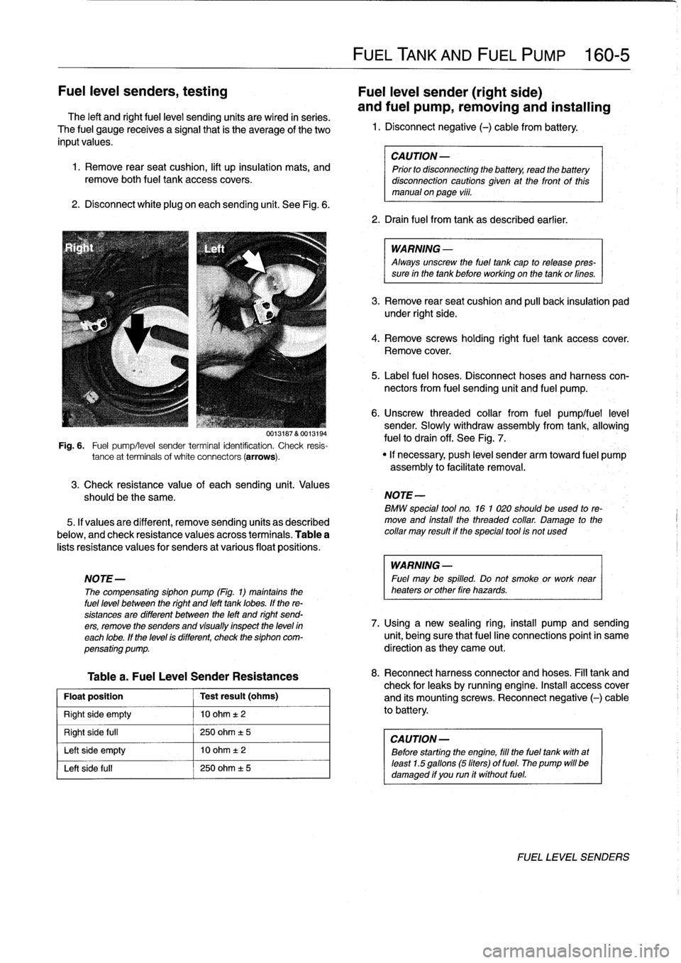
Disconnect
white
plug
on
each
sending
unit
.
See
Fig
.
6
.
3
.
Check
resistance
value
of
eachsending
unit
.
Values
should
be
the
same
.
5
.
If
valuesare
different,
remove
sending
units
as
described
below,
and
check
resistance
valuésacross
terminals
.
Table
a
lists
resistance
values
for
senders
at
various
float
positions
.
Table
a
.
Fuel
Leve¡
Sender
Resistances
Float
position
Test
result
(ohms)
Right
side
empty
10
ohm
t2
Right
side
full
250
ohm
±
5
Left
side
empty
10
ohm
t
2
Left
side
fui¡
250
ohm
±
5
FUEL
TANK
AND
FUEL
PUMP
160-
5
CAUTION
-
Prior
to
disconnecting
the
battery,
read
the
battery
disconnection
cautionsglven
at
the
front
of
this
manual
onpage
viii
.
2
.
Drain
fuel
from
tank
as
described
earlier
.
WARNING
-
Always
unscrew
the
fuel
tank
cap
to
release
pres-
sure
in
the
tank
before
working
on
the
tank
or
fines
.
3
.
Remove
rear
seat
cushion
and
pull
back
insulation
pad
under
right
side
.
4
.
Remove
screws
holding
rightfuel
tank
accesscover
.
Remove
cover
.
5
.
Label
fuel
hoses
.
Disconnect
hoses
and
harness
con-
nectors
from
fuel
sending
unit
and
fuel
pump
.
6
.
Unscrew
threaded
collar
from
fuel
pumplfuel
leve¡
sender
.
Slowly
withdraw
assembly
from
tank,allowing
fuelto
drain
off
.
See
Fig
.
7
.
0013187
&
0013194
Fig
.
6
.
Fuel
pump/leve¡
sender
terminal
identification
.
Check
resis-
tance
at
terminals
of
white
connectors
(arrows)
.
"
If
necessary,
push
leve¡
sender
arm
toward
fuel
pump
assembly
to
facilitate
removal
.
NOTE
-
BMW
special
tool
no
.
16
1
020
should
beused
to
re-
move
and
install
the
threaded
collar
.
Damage
to
the
collar
may
result
if
the
special
tool
is
not
used
WARNING
-
NOTE-
Fuel
may
be
spilled
.
Do
not
smoke
or
work
near
The
compensating
siphon
pump
(Fig
.
1)
maintains
the
heaters
or
other
fire
hazards
.
fuel
leve¡
between
the
right
and
left
tank
lobes
.
If
the
re-
sistances
are
different
between
the
left
and
right
send-
ers,
remove
the
senders
and
visually
inspect
the
leve)
in
7
.
Using
a
new
sealing
ring,
install
pump
and
sending
each
lobe
.
If
the
leve¡
is
different,
check
the
siphon
com-
unit,
being
sure
that
fuel
line
connections
point
in
same
pensating
pump
.
direction
as
they
carne
out
.
8
.
Reconnect
harnessconnector
and
hoses
.
Fill
tank
and
check
for
leaks
by
running
engine
.
Insta¡¡
access
cover
and
its
mountingscrews
.
Reconnect
negative
(-)
cable
to
battery
.
CAUTION
-
Before
starting
the
engine,
fill
the
fuel
tank
with
at
least
1
.5
gallons
(5liters)
of
fuel
.
The
pump
will
be
damaged
if
you
run
it
without
fuel
.
FUEL
LEVEL
SENDERS
Page 201 of 759
5
.
Slowly
add
coolant
until
it
spills
from
bleed
screws
.
When
coolant
spillíng
from
bleed
screws
is
free
of
air
bubbies,
tighten
screws
.
6
.
Run
engine
until
it
reaches
operatíng
temperature
.
Af-
ter
engine
has
cooled,
recheck
coolant
level
and
top
up
as
necessary
.
CAUTION-
Always
use
genuine
BMW
coolant
or
its
equiva-
lent
to
avoid
the
formation
of
harmful,
clogging
de-
posits
in
the
cooling
system
.
Use
of
other
antifreeze
solutions
may
be
harmful
to
the
cooling
system
.
Tightening
Torque
"
Radiator
bleed
screw
to
thermostat
housing
...
.
.
........
8
Nm
(71
in-lb)
Belt-driven
cooling
fan,
replacing
1
.
Usinga32
mm
wrench
on
fan
clutch
nut,
turn
wrench
quickly
in
a
clockwise
direction
(working
from
front
of
car)
to
loosen
.
Spin
fan
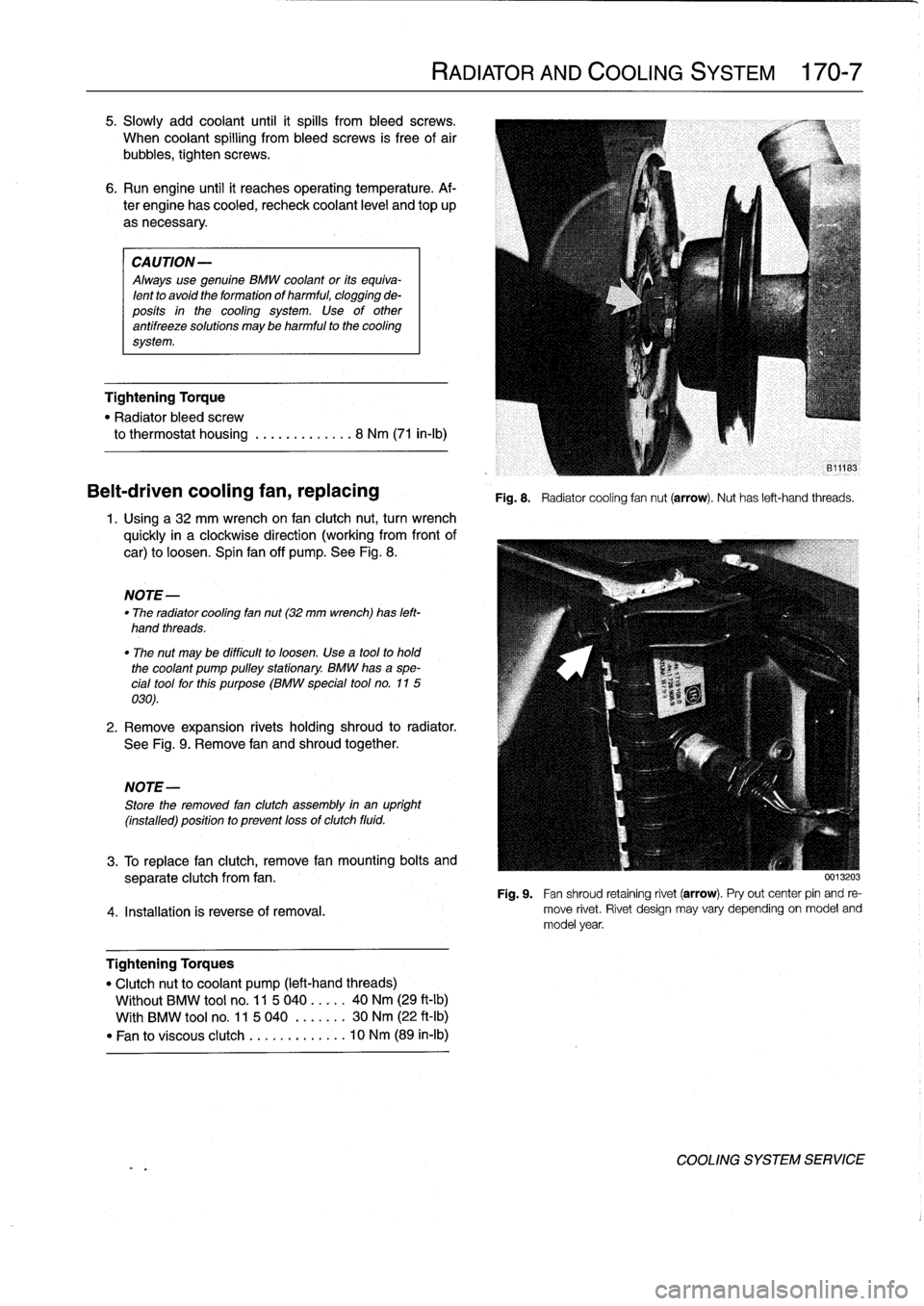
off
pump
.
See
Fig
.
8
.
NOTE-
"
The
radiator
cooling
fan
nut(32
mm
wrench)
has
left-
hand
threads
.
"
The
nut
may
be
difficult
to
loosen
.
Use
a
tool
to
hold
the
coolant
pump
pulleystationary
.
BMW
hasa
spe-
cial
tool
forthis
purpose
(BMW
special
tool
no
.
115
030)
.
2
.
Remove
expansion
rivets
holding
shroud
to
radiator
.
See
Fig
.
9
.
Remove
fan
and
shroud
together
.
NOTE-
Store
the
removed
fan
clutch
assembly
in
an
upright
(installed)
positionto
prevent
lossof
clutch
fluid
.
RADIATOR
AND
COOLING
SYSTEM
170-
7
Fig
.
8
.
Radiatorcooling
fannut
(arrow)
.
Nuthas
left-hand
threads
.
3
.
To
replace
fan
clutch,
remove
fan
mounting
bolts
and
separate
clutch
from
fan
.
Fig
.
9
.
Fan
shroud
retaining
rivet
(arrow)
.
Pryout
center
pin
and
re
4
.
Installation
is
reverse
of
rernoval
.
move
rivet
.
Rivet
design
may
vary
depending
on
model
and
model
year
.
Tightening
Torques
"
Clutchnut
to
coolant
pump
(left-hand
threads)
Wíthout
BMW
tool
no
.
11
5
040
.....
40
Nm
(29
ft-lb)
With
BMW
tool
no
.
11
5
040
.
......
30
Nm
(22
ft-Ib)
"
Fan
to
viscous
clutch
...
.
..
.
......
10
Nm
(89
in-lb)
0013203
COOLING
SYSTEM
SERVICE
Page 213 of 759
GENERAL
..
.
......
.
.
.
.....
.
...
.
.
.
.
.
.
.
.
200-1
Manual
Transmission
.
.
.....
.
.
.
.'
.
.
.
.
.
.
.
.
200-1
Automatic
Transmission
.........
.
.
.
.
.
.
.
.
200-1
Transmission
ID
Codes
..........
.
.
.
.
.
.
.
.
200-2
GENERAL
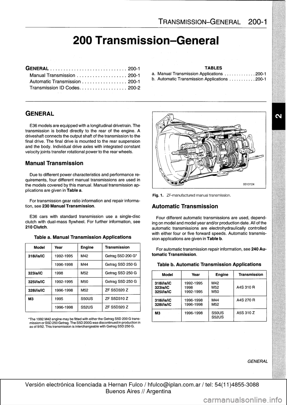
E36
models
areequipped
with
a
longitudinal
drivetrain
.
The
transmission
is
bolted
directly
to
the
rear
of
the
engine
.
A
driveshaft
connects
the
output
shaft
of
thetransmission
to
the
final
drive
.
The
final
drive
is
mounted
lo
the
rear
suspension
and
the
body
.
Individual
drive
axles
with
integrated
constant
velocity
joints
transfer
rotational
power
to
the
rear
wheels
.
Manual
Transmission
Due
to
different
power
characteristics
and
performance
re-
quirements,
four
different
manual
transmissions
are
used
in
the
models
coveredby
this
manual
.
Manual
transmission
ap-
plications
are
given
in
Table
a
.
TRANSMISSION-GENERAL
200-1
200
Transmission-General
TABLES
a
.
Manual
Transmission
Applications
..
...........
200-1
b
.
Automatic
Transmission
Applications
...........
200-1
Fig
.
1
.
ZF-manufacturedmanual
transmission
.
For
transmission
gear
ratio
information
and
repair
informa-
tion,
see
230
Manual
Transmission
.
Automatic
Transmission
E36
carswith
standard
transmission
use
a
single-disc
clutch
with
dual-mass
flywheel
.
For
further
information,
see
210
Clutch
.
Table
a
.
Manual
Transmission
Applications
Model
Year
Engine
Transmission
318ifisfC
1992-1995
M42
Getrag
S5D
200
G'
1996-1998
M44
Getrag
S5D
250
G
323is/iC
1998
M52
Getrag
S5D
250
G
325ifsriC
1992-1995
M50
Getrag
S5D
250
G
3281/isfC
1996-1998
M52
ZF
S5D320
Z
M3
1995
S50US
ZF
S5D310
Z
1996-1998
S52US
ZF
S5D320
Z
'The
1992
M42
engine
may
be
fitted
witheither
the
Getrag
SSD
200
G
trans-
mission
or
S5D
250
Getrag
.
The
S5D
200G
was
discontinued
in
production
in
as
of
9/92
.
Thistransmission
is
interchangeable
with
Getrag
S5D
250
G
.
Four
different
automatic
transmissions
are
used,
depend-
ing
on
model
and
model
year
and/or
production
date
.
All
of
the
automatic
transmissions
are
electrohydraulically
controlled
with
either
four
or
five
forward
speeds
.
Automatic
transmis-
sion
applications
are
given
in
Table
b
.
For
automatic
transmission
repair
information,
see
240Au-
tomatic
Transmission
.
Table
b
.
Automatic
Transmission
Applications
Model
1
Year
1
Engine
1
Transmission
318i1is/1C
1992-1995
~
M42
323isfiC
1998
M52
A4S
310
R
3251/is/1C
1992-1995
M50
3181/isfC
11996-1998
M44
A4S
270
R
328i/is/1C
1996-1998
M52
M3
1996-1998
S50US
I
A5S
310
Z
S52US
GENERAL
Page 227 of 759
13
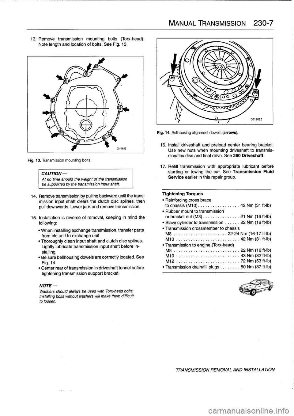
.
Remove
transmission
mounting
bolts
(Torx-head)
.
Note
length
and
location
of
bolts
.
See
Fig
.
13
.
Fig
.
13
.
Transmission
mounting
bolts
.
0611642
CA
UTION-
Atno
time
should
the
weight
of
thetransmission
be
supported
by
the
transmission
inputshaft
.
NOTE
-
Washers
should
always
be
used
with
Torx-head
bolts
.
Installing
bolts
without
washers
will
make
them
difficult
to
loosen
.
MANUAL
TRANSMISSION
230-
7
Fig
.
14
.
Bellhousing
alignment
dowels
(arrows)
.
16
.
Install
driveshaft
and
preload
center
bearing
bracket
.
Usenew
nuts
when
mounting
driveshaft
to
transmis-
síon/flex
disc
and
final
drive
.
See
260
Driveshaft
.
17
.
Refill
transmission
with
appropriate
lubricant
before
starting
or
towingthe
car
.
See
Transmission
Fluid
Service
earlier
in
this
repair
group
.
14
.
Remove
transmission
by
pulling
backward
until
the
trans-
Tightening
Torques
mission
inputshaft
clears
the
clutch
disc
splines,
then
"
Reinforcing
cross
brace
pulí
downwards
.
Lower
jack
andremove
transmission
.
to
chassis
(M10)
.
...
.............
42
Nm
(31
ft-Ib)
"
Rubber
mount
to
transmission
15
.
Installation
is
reverse
of
removal,
keeping
in
mind
the
or
bracket
nut
(M8)
.
...
.
...
.......
21
Nm
(16
ft-Ib)
following
:
"
Slave
cylinder
to
transmission
......
22
Nm
(16
ft-Ib)
"
When
installing
exchange
transmission,
transfer
parts
"
Transmission
crossmember
to
chassis
from
old
unit
to
exchange
unit
M8
...............
.
.
...
..
22-24
Nm
(16-17
ft-Ib)
"
Thoroughly
clean
inputshaft
and
clutch
disc
splines
.
M10
..............
.
..
..
.......
42
Nm
(31
ft-Ib)
Lightly
lubrícate
transmission
inputshaft
before
in-
"
Transmission
to
engine
(Torx-head)
stalling
.-
M8
..
..................
..
.
..
..
22
Nm
(16
ft-Ib)
"
Be
sure
bellhousing
dowels
are
correctly
located
.
See
M10
.
.................
...
.
..
..
43
Nm
(32
ft-Ib)
Fig
.
14
.
M12
.
..................
..
.
..
..
72
Nm
(53
ft-Ib)
"
Center
rear
of
transmission
in
driveshaft
tunnel
before
"
Transmission
drain/fill
plugs
.
..
.
..
..
50
Nm
(37
ft-Ib)
tightening
transmission
support
bracket
.
TRANSMISSION
REMOVAL
AND
INSTALLATION
Page 229 of 759
AUTOMATIC
TRANSMISSION
240-1
240
Automatic
Transmission
GENERAL
.....
.
.
.
.
.
.
.
.
.
.
.
.
.
.........
.
240-1
TRANSMISSION
REMOVAL
AND
INSTALLATION
..................
.
.
.
.
.240-4
TRANSMISSION
SERVICE
.
.
.
.
.
.......
.
240-1
Transmission,
removing
and
installing
....
.
.
.240-4
ATF
leve¡,
checking
..
.
.
.
.
.
.
.
.
.
..........
240-1
ATF,
draining
and
filling
.
.
.
.
.
.
.
..........
240-2
TABLE
a
.
Automatic
Transmission
Gear
Ratios
.......
..
.
.
240-1
GENERAL
TRANSMISSION
SERVICE
lo
Automatic
transmissions
are
identified
by
code
letters
ATF
leve¡,
checking
foundon
a
data
plate
located
on
the
sideof
thetransmission
case,
behind
the
manual
valve
lever
.
See
200Transmis-
The
automatic
transmissions
installed
in
the
E36
models
sion-General
for
application
information
.
Forgear
ratio
spec-
are
normally
filled
with
Dexron
III
automatic
transmission
fluid
ifications,
see
Table
a
.
(ATF),
although
alternative
fluids
have
been
installed
from
the
factory,
depending
on
transmission
type
and
model
year
.
CAUTION-
Some
transmíssions
are
filled
with
a
special
BMW
"lifetime"
ATF
does
not
circulate
unless
the
engine
is
run-
automatic
transmission
fluid,
which
does
not
require
periodic
ning
.
When
towing
an
automafic
transmission
ve-
fluid
changes
.
hicle,
usea
flat-bed
truck
or
ralse
the
rear
wheels
off
the
ground
.
CAUTION-
Mixing
different
types
of
transmission
fluids
will
The
electronic
transmission
control
module
(TCM)
monitors
lead
to
transmission
failure
.
transmissionoperation
for
faults
and
alerts
the
driver
by
illumi-
nating
the
transmission
fault
indicator
on
the
instrument
pan-
el
.
On-board
diagnostic
codes
stored
in
the
TCM
mustbe
NOTE-
downloaded
and
interpreted
by
trained
technicians
using
spe-
The
transmission
lubricant
instafed
can
be
foundona
cial
BMW
diagnostic
equipment
.
type
plate
on
the
side
of
the
transmission
.
In
addition,
a
sticker
may
be
located
on
the
fluid
sump
indicatingthe
typeof
transmission
lubricant
used
.
Ifin
doubt,
con
NOTE-
sult
an
authorized
BMW
dealer
for
altemate
fluid
use
Internal
repairs
to
the
automatic
transmission
require
and
current
information
regardingtransmission
operat-
special
service
equipment
and
knowledge
.
If
it
is
deter-
ing
fluids
.
mined
thatinterna¡
service
is
required,
consult
en
au-
thorízedBMWdealerabouta
factoryreconditioned
unit
The
transmission
is
not
equipped
with
a
dipstick
.
Checking
or
a
transmission
rebuild
.
the
ATF
leve¡
requires
measuring
and
maintaining
a
specified
ATF
temperature
during
the
checking
procedure
.
The
check-
ing
temperature
is
not
fully
warm
orcold
(the
ATF
sump
should
be
approximately
warm
to
the
touch)
.
Table
a
.
Automatic
Transmission
Gear
Ratios
Transmission
MS
310R
(THM-R1)
MS
310R
(THM-Rl)
MS
310Z(5HP
18)
I
MS
270R
(THM-R1)
(1992-1993)(1993-on)
Gear
ratios
:
1st
2
.40
2
.86
3
.67
2
.86
2nd
1
.47
1
.62
2
.00
1
.62
3rd
1
.00
1
.00
1.41
1
.00
4th
0
.72
0
.72
1
.00
0
.72
5th
-
-
0
.74
-
Reverse
2
.00
2
.00
4
.10
2
.00
TRANSMISSIONSERVICE
Page 234 of 759
240-
6
AUTOMATIC
TRANSMISSION
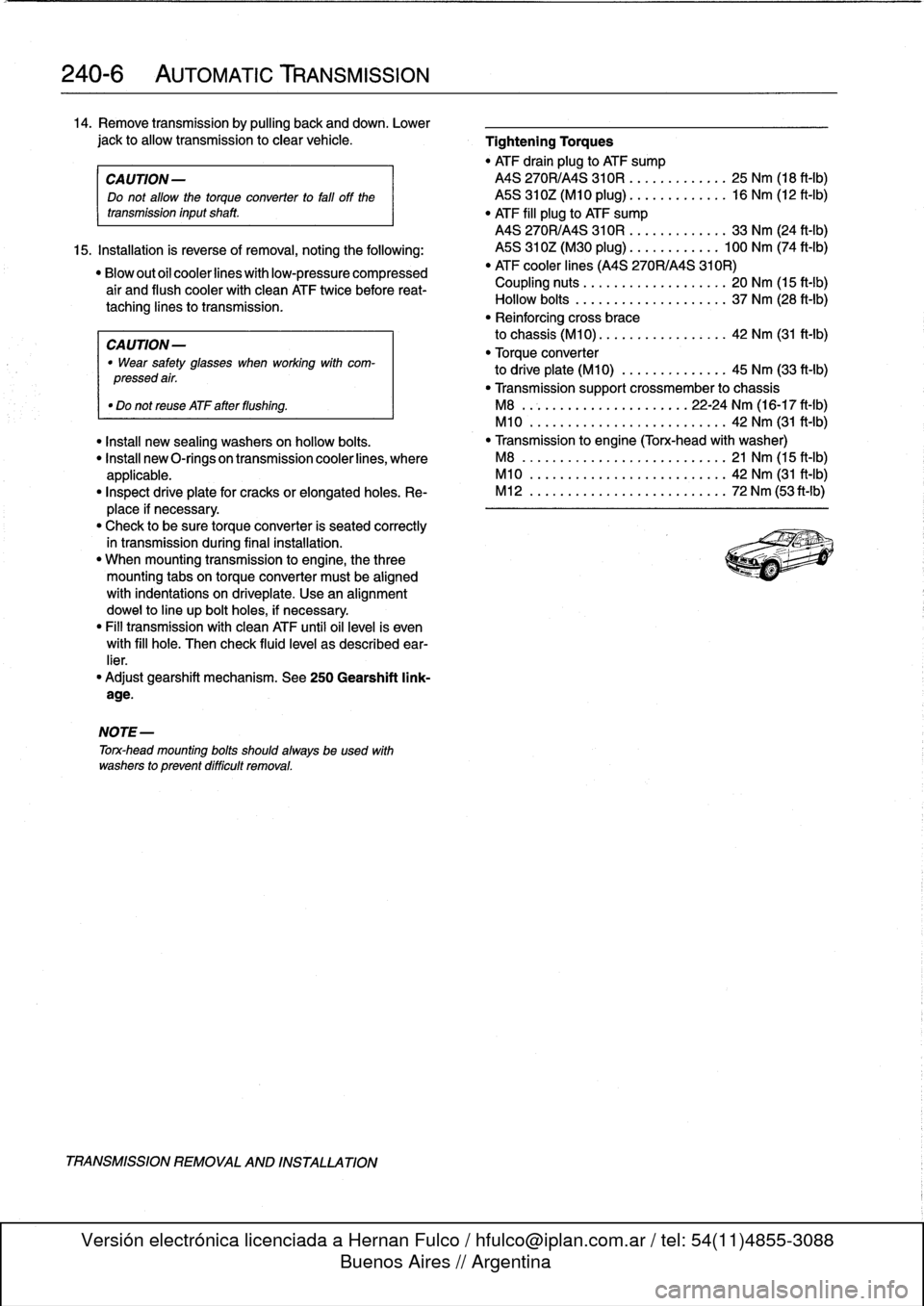
14
.
Remove
transmission
by
pulling
back
and
down
.
Lower
jack
to
allow
transmission
to
clear
vehicle
.
Tightening
Torques
"
ATF
drain
plug
to
ATF
sump
CA
UTION-
MS
270R/A4S
310R
....
..
....
.
..
25
Nm
(18
ft-Ib)
Do
not
allow
the
torque
converter
to
fati
off
the
ASS
310Z(M10
plug)
..
..
..
.
.
..
.
..
16
Nm
(12
ft-Ib)
transmission
inputshaft
.
"
ATF
fill
plug
to
ATF
sump
MS
270R/A4S
310R
..
..
....
..
..
.
33
Nm
(24
ft-Ib)
15
.
Installation
is
reverse
of
removal,
noting
the
following
:
MS
310Z(M30
plug)
......
.
.
..
.
.
100
Nm
(74
ft-Ib)
"Blowoutofcoolerlineswithlow-pressurecompressed
"
ATF
cooler
lines
(A4S
270R/A4S
310R)
air
and
flush
coolerwith
clean
ATF
twice
before
reat-
Coupling
nuts
............
.
.
..
..
.
20
Nm
(15
ft-Ib)
taching
lines
to
transmission
.
Hollow
bolts
.........
.
.....
..
..
.
37
Nm
(28
ft-Ib)
"
Reinforcing
cross
brace
CAUTION-
to
chassis
(M10)
.............
.
..
.
42
Nm
(31
ft-Ib)
"
Wear
safety
glasses
when
working
with
com-
"
Torque
converter
pressedair
.
to
driveplate
(M10)
.........
..
.
..
45
Nm
(33
ft-Ib)
"
Transmissionsupport
crossmember
to
chassis
"
Do
not
reuse
ATF
after
flushing
.
M8
......................
22-24
Nm
(16-17
ft-1b)
M10
................
.
....
..
.
..
42
Nm
(31
ft-Ib)
"
Install
new
sealing
washers
on
hollow
bolts
.
"
Transmissíon
to
engine
(Torx-head
with
washer)
"
Insta¡¡
new
O-rings
on
transmission
cooler
lines,
where
M8
......................
..
.
..
21
Nm
(15
ft-Ib)
applicable
.
M10
.....................
..
..
.
42
Nm
(31
ft-Ib)
"
Inspect
driveplate
for
cracks
or
elongatedholes
.
Re-
M12
................
.
....
..
.
..
72
Nm
(53ft-Ib)
place
if
necessary
.
"
Check
to
be
sure
torque
converter
is
seated
correctly
in
transmission
during
final
installation
.
"
When
mounting
transmission
to
engine,
the
three
mounting
tabs
on
torque
converter
must
be
aligned
with
indentations
on
driveplate
.
Use
an
alignment
dowel
to
line
up
bolt
holes,
if
necessary
.
"
Fill
transmission
with
clean
ATF
until
oil
leve¡
is
even
with
fill
hole
.
Then
check
fluid
leve¡
as
described
ear-
lier
.
"
Adjust
gearshift
mechanism
.
See
250
Gearshift
link-
age
.
NOTE-
Torx-head
mounting
bolts
shouldalwaysbe
used
with
washers
to
prevent
difficult
removal
.
TRANSMISSION
REMOVAL
AND
INSTALLATION
Page 241 of 759
DRIVESHAFT
SERVICE
.
...
.
.
.
...
.
..
.
.
.260-3
Driveshaft,
aligning
...............
.
...
.
.
260-3
Driveshaft,
removing
..............
.
.
.
.
.
.
260-4
260
Driveshaft
DRIVESHAFT
260-1
GENERAL
.
.
.
.
.
.
.
.....
.
.
.
........
.
...
.
260-1
Driveshaft,
installing
.
....
.
..
.
............
260-4
Flex-disc,
replacing
.....
.
.
.
.............
260-5
TROUBLESHOOTING
..
.
.
.
...
.
.........
260-1
Center
bearing
assembly,
replacing
.
......
.260-6
Frontcentering
guide,
replacing
..
.
.......
.
260-7
TABLE
a
.
Driveshaft
Troubleshooting
.
.
...
......
.
....
..
.
.
260-2
GENERAL
NOTE-
For
rear
drive
axlerepair
information,
see330
Rear
The
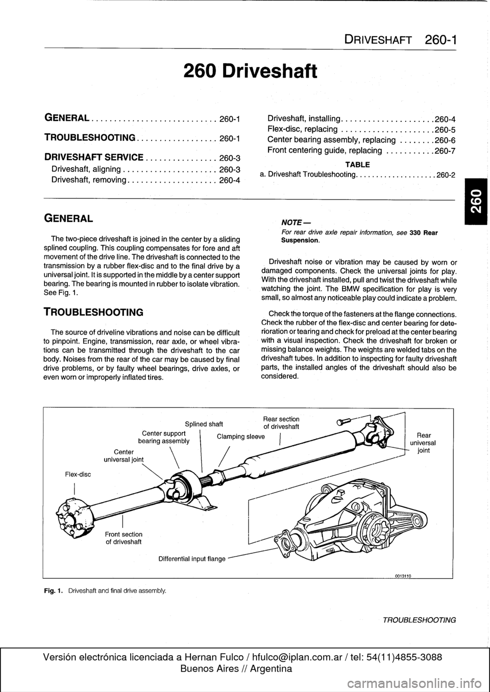
two-piece
driveshaft
is
joined
in
thecenter
by
a
sliding
Suspension
.
splined
coupling
.
This
coupling
compensates
for
fore
and
aft
movement
of
the
drive
line
.
The
driveshaft
ís
connected
to
the
Driveshaft
noise
or
vibration
may
be
caused
by
worn
or
transmission
bya
rubber
flex-disc
and
to
the
final
drive
by
a
damaged
components
.
Check
the
universal
joints
for
play
.
universal
joint
.
It
is
supported
in
the
micidle
by
a
center
support
With
the
driveshaft
installed,
pull
and
twist
the
driveshaft
while
bearing
.
The
bearing
is
mounted
in
rubber
to
isolate
vibration
.
watching
the
joint
.
The
BMW
specificationfor
play
is
very
See
Fig
.
1
.
small,
so
almost
any
noticeableplay
could
indicate
a
problem
.
TROU
BLESHOOTING
Check
thetorque
of
thefasteners
at
the
flange
connections
.
Check
therubber
of
the
flex-disc
and
center
bearing
for
dete
The
source
of
driveline
vibrations
and
noise
can
be
difficult
rioration
or
tearíng
and
check
for
preload
at
the
center
bearing
to
pinpoint
.
Engine,
transmission,
rear
axle,
or
wheel
vibra-
with
a
visual
inspection
.
Check
the
driveshaft
for
broken
or
tions
can
be
transmitted
through
the
driveshaft
to
the
car
missing
balance
weights
.
The
weights
are
welded
tabs
on
the
body
.
Noises
from
the
rear
of
thecar
may
be
caused
by
final
driveshaft
tubes
.
In
addition
to
inspecting
for
faulty
driveshaft
drive
problems,
orby
faulty
wheel
bearings,
drive
axies,
or
parts,
the
installed
angles
of
the
driveshaft
should
also
be
evenworn
or
improperly
inflatedtires
.
considered
.
Flex-disc
Center
universal
joint
Fig
.1
.
Driveshaft
and
final
drive
assembly
.
Rear
section
Splined
shaft
of
driveshaft
Center
support
`
Clamping
sleeve
bearíng
assembly
Differential
inputflange
0013110
TROUBLESHOOTING