ECO mode BMW M3 1998 E36 Owner's Guide
[x] Cancel search | Manufacturer: BMW, Model Year: 1998, Model line: M3, Model: BMW M3 1998 E36Pages: 759
Page 336 of 759
512-
6
DOORWINDOWS
0013061
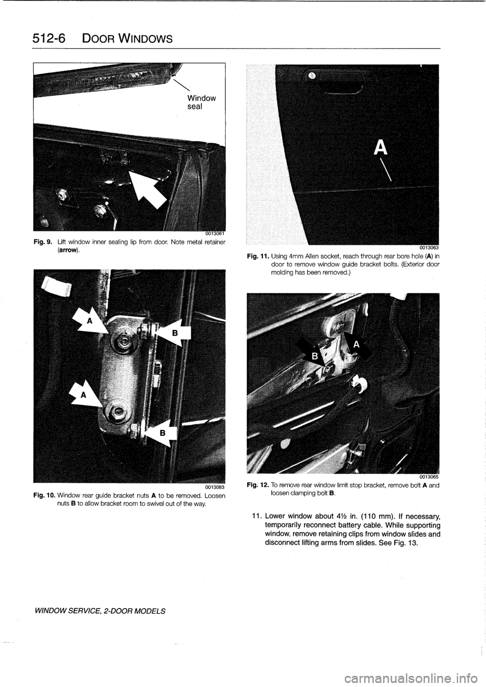
Fig
.
9
.
Lift
window
inner
sealing
lip
fromdoor
.
Note
metal
retainer
(arrow)
.
0013083
Fig
.
10
.
Window
rear
guíde
bracket
nuts
A
to
be
removed
.
Loosen
nuts
B
to
allow
bracket
room
to
swivel
out
of
the
way
.
WINDOW
SERVICE,
2-DOOR
MODELS
0013063
Fig
.
11
.
Using
4mm
Allen
socket,
reach
through
rear
bore
hole
(A)
in
door
to
remove
window
guide
bracket
boits
.
(Exterior
door
molding
hasbeen
removed
.)
0013065
Fig
.
12
.
Toremove
rear
window
limit
stop
bracket,
remove
bolt
A
and
loosen
clamping
bolt
B
.
11
.
Lower
window
about
4
1
/2
in
.
(110
mm)
.
If
necessary,
temporarily
reconnect
battery
cable
.
While
supporting
window,
remove
retaining
clips
from
window
slides
and
disconnect
lifting
arms
from
slides
.
See
Fig
.
13
.
Page 337 of 759
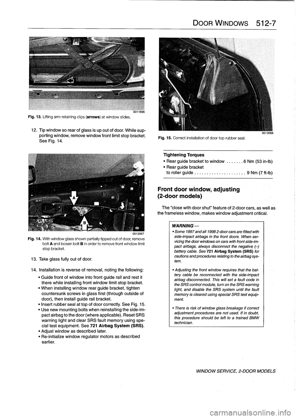
Fig
.
13
.
Lifting
arm
retaining
clips
(arrows)
at
window
slides
.
12
.
Tip
window
so
rear
ofglass
is
up
out
of
door
.
While
sup-
porting
window,
remove
window
front
limit
stopbracket
.
See
Fig
.
14
.
0013067
Fig
.
14
.
With
window
glass
shown
partially
tipped
out
of
door,
remove
bolt
A
and
loosen
bolt
B
in
order
to
remove
front
window
limit
stop
bracket
.
13
.
Take
glass
fully
out
of
door
.
14
.
Installation
is
reverse
of
removal,notingthe
following
:
"
Guide
front
of
window
into
front
guide
rail
and
rest
it
therewhile
installing
front
window
limit
stop
bracket
.
"
When
installing
window
rear
guide
bracket,
tighten
countersunk
screws
in
glass
first
(throughoutside
of
door),
then
install
guide
rail
bracket
.
"
Insert
rubber
sea¡
at
top
of
door
correctly
See
Fig
.
15
.
"
Use
new
mounting
bolts
when
reinstalling
the
side-im-
pactairbag
to
the
door
(where
applicable)
.
Reset
SRS
warning
light
and
clear
SRS
fault
memory
using
spe-
cial
test
equipment
.
See
721
Airbag
System
(SRS)
.
"
Adjust
window
as
described
later
.
"
Re-inítialize
window
regulator
motors
as
described
earlier
.
DOOR
WINDOWS
512-
7
Fig
.
15
.
Correct
installation
of
door
toprubber
seal
.
Tightening
Torques
"
Rear
guide
bracket
to
window
.......
6
Nm
(53
in-lb)
"
Rear
guide
bracket
to
roller
guide
..
.
...
...............
9
Nm
(7
ft-Ib)
Front
door
window,
adjusting
(2-door
modeis)
The
"closewith
door
shut"
feature
of
2-door
cars,
as
well
as
the
frameless
window,
makeswindow
adjustment
critical
:
WARNING
-
"
Some
1997
and
afl
1998
2-door
cars
are
fitted
with
side-impact
airbags
in
the
front
doors
.
When
ser-
vicingthe
door
windows
on
cars
with
front
side-im-
pact
airbags,
always
disconnect
the
negative
(-)
battery
cable
.
See
721Airbag
System
(SRS)
for
cautions
and
procedures
relating
to
the
airbag
sys-
tem
.
"
Adjusting
the
front
window
requires
that
the
bat-
tery
cable
be
reconnected
with
the
side-impact
airbag
disconnected
.
This
will
set
a
fault
code
in
the
SRS
control
module,
turn
on
the
SRS
warning
light,
and
disable
the
SRS
system
until
the
fault
memory
is
cleared
using
special
SRS
test
equip-
ment
.
"
There
is
risk
of
window
glass
breakage
if
correct
adjustment
proceduresare
not
used
.
If
in
doubt,
this
procedureshouldbe
left
to
a
trained
BMW
technician
.
WINDOW
SERVICE,
2-DOOR
MODELS
Page 338 of 759
512-
8
DOOR
WINDOWS
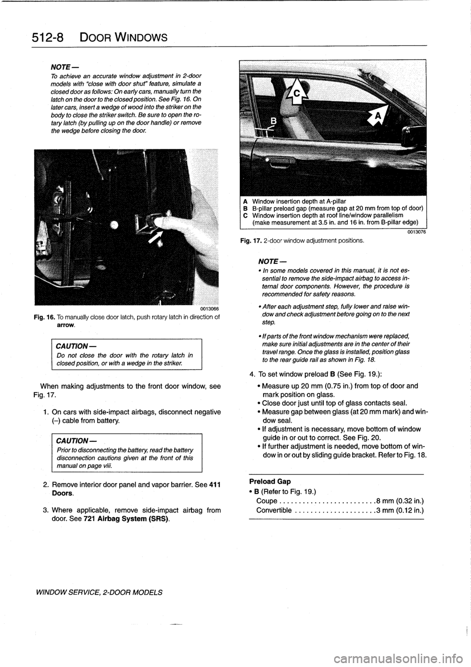
NOTE-
To
achieve
an
accurate
window
adjustment
in
2-door
models
with
"close
with
door
shut"
feature,
simulate
a
closed
dooras
follows
:
On
early
cars,
manually
turn
the
latch
on
the
door
to
the
closed
position
.
See
Fig
.
16
.
On
latercars,
insert
a
wedge
of
wood
into
the
striker
on
the
body
to
close
the
striker
switch
.
Be
sure
to
open
thero-
tary
latch
(by
pulling
upon
the
door
handle)
or
remove
the
wedge
before
closing
the
door
.
0013066
Fig
.
16
.
To
manually
close
door
latch,
push
rotary
latch
in
direction
of
arrow
.
CAUTION-
Do
not
close
the
door
with
therotary
latch
in
closed
position,
orwith
a
wedge
in
the
striker
.
WINDOW
SERVICE,
2-DOOR
MODELS
A
Window
insertion
depth
at
A-pillar
B
B-pillar
preload
gap
(measure
gap
at
20
mm
from
top
of
door)
C
Window
insertion
depth
at
roof
line/window
parallelism
(make
measurement
at
3
.5
in
.
and
16
in
.
from
B-pillar
edge)
Fig
.
17
.
2-door
window
adjustment
positions
.
NOTE-
In"
some
models
covered
inthis
manual,
it
is
not
es-
sential
to
remove
the
side-impact
airbag
to
access
in-
terna¡
door
components
.
However,
the
procedure
is
recommended
for
safety
reasons
.
"
After
each
adjustment
step,
fully
lower
and
raise
win-
dow
and
check
adjustment
before
goingon
to
the
next
step
.
"
1f
parts
of
the
front
window
mechanism
were
replaced,
make
sure
initial
adjustments
are
in
the
center
of
their
travel
range
.
Once
the
glass
isinstalled,
position
glass
to
the
rear
guide
rail
as
shown
in
Fig
.
18
.
4
.
To
set
window
preload
B
(See
Fig
.
1
g
.):
0013076
When
making
adjustments
to
the
front
door
window,
see
"
Measure
up
20
mm
(0
.75
in
.)
from
topof
door
and
Fig
.
17
.
mark
position
on
glass
.
"
Close
door
just
until
top
of
glass
contacts
seal
.
1
.
On
cars
with
side-impact
airbags,
disconnect
negative
"
Measure
gap
between
glass
(at
20
mm
mark)
and
win-
(-)
cable
from
battery
.
dow
seal
.
"
If
adjustment
is
necessary,
move
bottom
of
window
CAUTION-
guide
inor
out
to
correct
.
See
Fig
.
20
.
Prior
to
disconnecting
the
battery,
read
the
battery
"
If
further
adjustment
is
needed,
move
bottom
ofwin-
disconnection
cautionsgiven
at
the
front
of
this
dow
in
or
out
by
sliding
guide
bracket
.
Refer
to
Fig
.
18
.
manual
on
page
viii
.
2
.
Remove
interior
door
panel
and
vapor
barrier
.
See
411
Preload
Gap
Doors
.
"
B
(Referto
Fig
.
1
g
.)
Coupe
......................
.
.
.8
mm
(0
.32
in
.)
3
.
Where
applicable,
remove
side-impact
airbag
from
Convertible
..................
.
..
3
mm
(0
.12
in
.)
door
.
See
721
Airbag
System
(SRS)
.
Page 339 of 759
5tud
center
Window
glass
surface
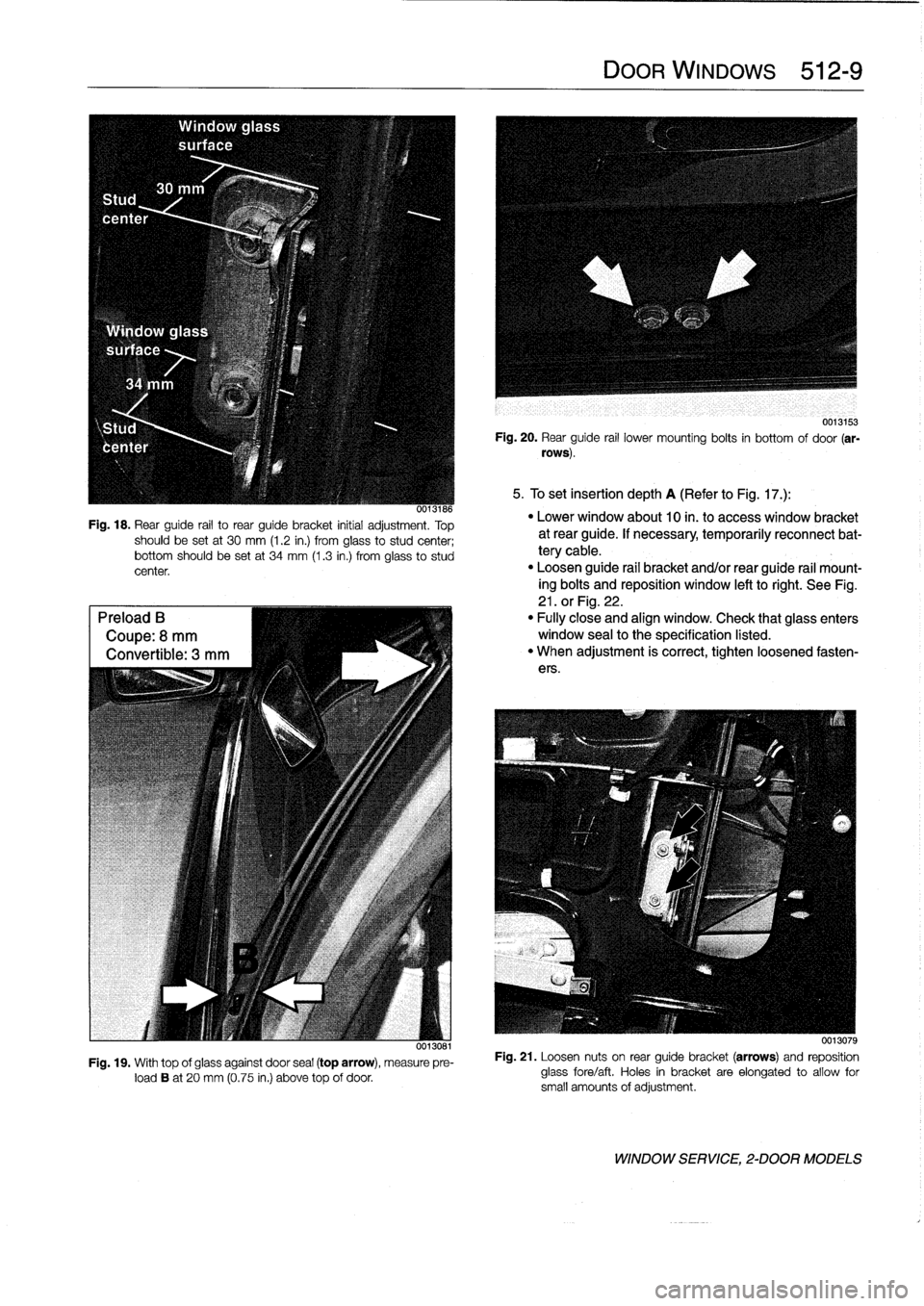
Fig
.
18
.
Rear
guide
rail
to
rear
guide
bracket
initial
adjustment
.
Top
should
be
setat
30
mm
(1
.2
in
.)
from
glass
to
studcenter
;
bottom
should
be
set
at
34
mm
(1
.3
in
.)
from
glass
to
stud
center
.
Preload
B
Coupe
:
8
mm
Convertible
:
3
mm
0013081
Fig
.
19
.
With
top
of
glassagainst
door
sea¡(top
arrow),
measure
pre-load
B
at
20
mm
(0
.75
in
.)
above
top
of
door
.
DOOR
WINDOWS
512-
9
0013153
Fig
.
20
.
Rear
guide
rail
lower
mounting
bolts
in
bottom
of
door
(ar-
rows)
.
5
.
To
set
insertion
depth
A
(Referto
Fig
.
17
.)
:
"
Lowerwindow
about
10
in
.
t
o
access
window
bracket
at
rear
guide
.
If
necessary,
temporarily
reconnect
bat-
tery
cable
.
"
Loosen
guide
rail
bracket
and/or
rear
guide
rail
mount-
ing
bolts
and
reposition
window
left
to
right
.
See
Fig
.
21
.
orFig
.
22
.
"
Fully
close
and
align
window
.
Check
that
glass
enters
window
sea¡
to
the
specification
listed
.
"
When
adjustment
is
correct,
tighten
loosened
fasten-
ers
.
0013079
Fig
.
21
.
Loosen
nuts
on
rear
guide
bracket
(arrows)
and
reposition
glass
fore/aft
.
Holes
in
bracket
areelongated
to
allow
for
small
amounts
of
adjustment
.
WINDOW
SERVICE,
2-DOOR
MODELS
Page 340 of 759
512-
1
0
DOOR
WINDOWS
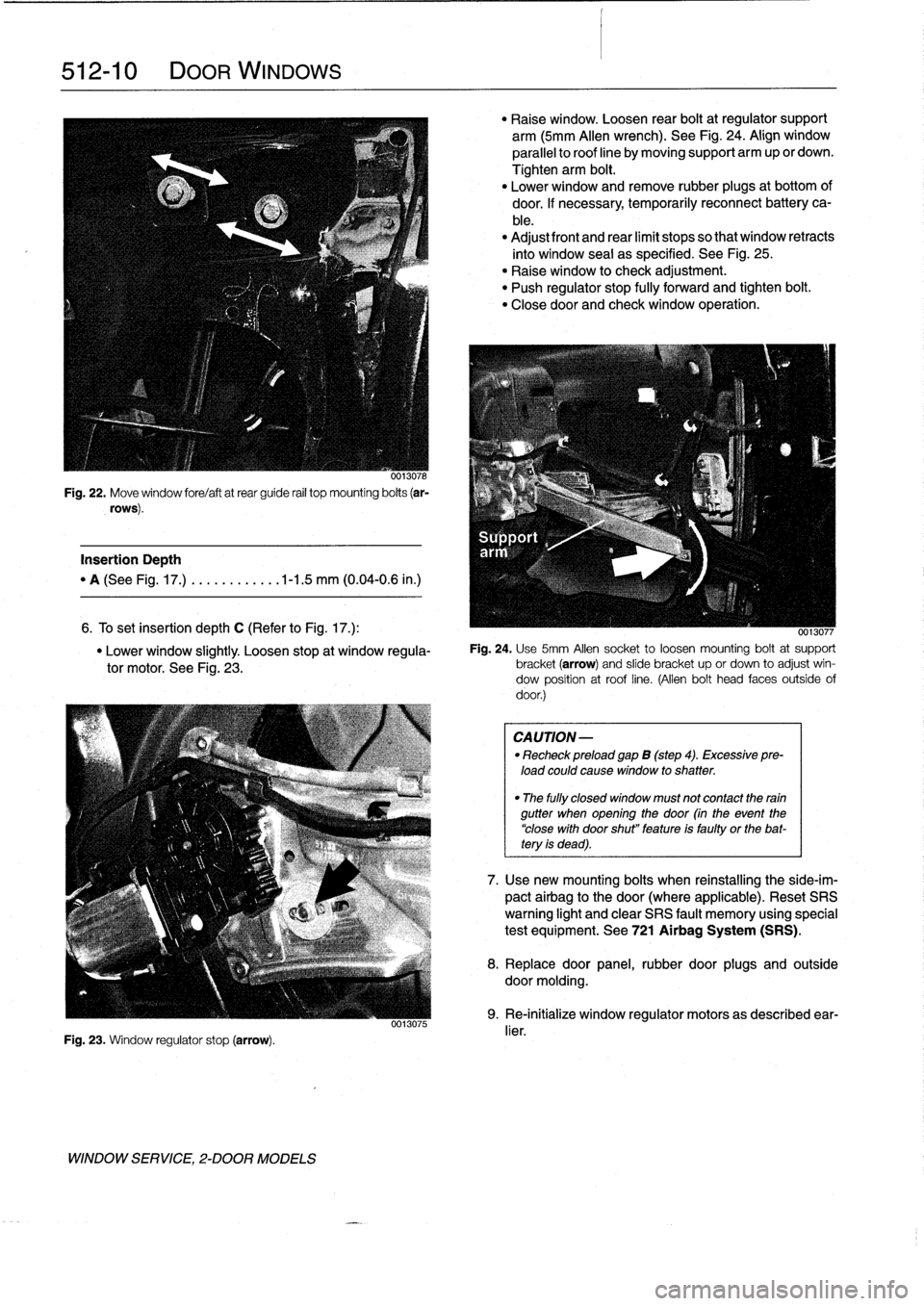
0013078
Fig
.
22
.
Move
window
fore/aftatrear
guide
rail
top
mounting
bolts
(ar-
rows)
.
Insertion
Depth
"
A
(See
Fig
.
17
.)
.
..........
.1-1
.5
mm
(0
.04-0
.6
in
.)
6
.
To
set
Insertion
depth
C
(Refer
to
Fig
.
17
.)
:
"
Lower
window
slightly
.
Loosen
stop
at
window
regula-
tor
motor
.
See
Fig
.
23
.
Fig
.
23
.
Window
regulator
stop
(arrow)
.
WINDOW
SERVICE,
2-DOOR
MODELS
0013075
"
Raise
window
.
Loosen
rear
boltat
regulator
support
arm
(5mm
Allen
wrench)
.
See
Fig
.
24
.
Align
window
parallelto
roof
line
by
moving
support
arm
up
or
clown
.
Tighten
arm
bolt
.
"
Lower
window
and
remove
rubber
plugs
at
bottom
of
door
.
If
necessary,temporarily
reconnect
battery
ca-
ble
.
"
Adjust
front
and
rear
limit
stops
so
that
window
retracts
into
window
seal
as
specified
.
See
Fig
.
25
.
"
Raise
window
to
check
adjustment
.
"
Push
regulator
stop
fully
forward
and
tighten
bolt
.
"
Closedoor
and
check
window
operation
.
0013077
Fig
.
24
.
Use
5mm
Afen
socket
to
loosen
mounting
boltat
support
bracket(arrow)
and
slide
bracket
up
or
clown
to
adjust
win-
dow
position
at
roof
line
.
(Allen
bolt
head
faces
outside
of
door
.)
CAUTION
-
"
Recheck
preload
gap
B
(step
4)
.
Excessive
pre-
load
could
cause
window
to
shatter
.
"
The
fully
closed
window
must
not
contact
the
rain
gutter
when
opening
the
door
(in
the
event
the
"close
with
door
shut"
feature
is
faulty
or
the
bat-tery
is
dead)
.
7
.
Usenew
mounting
bolts
when
reinstalling
the
side-im-
pact
airbag
to
the
door
(where
applicable)
.
Reset
SRS
warning
light
and
clear
SRS
fault
memory
using
special
test
equipment
.
See
721
Airbag
System
(SRS)
.
8
.
Replace
door
panel,
rubber
door
plugs
and
outside
doormolding
.
9
.
Re-initialize
window
regulator
motors
as
described
ear-
lier
.
Page 349 of 759
515
Central
Locking
and
Anti-Theft
GENERAL
.....
.
.
.
.
.
.
.
..:
.
.
.
......
.
.
.
.
515-1
Luggage
compartment
locking
actuator,
removing
and
installing
.
.
.
.
.
...........
.
515-6
DOOR
HANDLES
AND
LOCKS
.........
515-1
LOCKING
SYSTEM
AND
Front
door
lock,
removing
and
installing
....
.515-1
ELECTRONIC
IMMOBILIZATION
......
.515-7
Front
door
handle,
removing
and
installing
...
515-3
Rear
door
lock,
removing
and
installing
.....
515-4
Central
Locking
System(ZVM)
.
.
.
.
.......
.
515-7
Rear
door
handle,
removing
and
installing
...
515-5
Central
Body
Electronics
(ZKE
IV)
.
.
.......
.515-8
Electronic
Immobilization
System
(EWS)
.
.
.
.
.515-8
Door
striker,
rep
lacing
.
.
.
.
.
.
.
.
.
..........
515-6
EWS
II
control
module,
re
lacin
515-10
LOCKING
ACTUATORS
.
.
.
.
.
.
..........
515-6
Ring
antenna,
replacing
.
.
.
.
.
.
.
.
.
.
...
.
.
.
.
515-10
Door
Locking
Actuator
.
.
.
.
.
.
.
.
..........
515-6
EWS
II
transmitter/receiver
module,
replacing
...........
.
.
.
.
.
.
.
.
.
.
.
.
.
.
.
.
515-11
GENERAL
This
section
covers
repair
information
for
the
central
locking
and
the
anti-theft
systems
.
Keep
in
mind
that
E36
cars
are
CA
UTION-
equipped
with
sophisticated
and
self-diagnostic
electrical
sys-
Prior
to
disconnecting
the
battery,
read
the
battery
tems
.
When
experiencing
malfunctions
relatinglo
the
central
disconnection
cautions
given
at
the
front
of
this
locking
or
the
anti-theft
system,
it
is
recommended
that
the
manual
onpage
vi¡¡
.
systembe
diagnosed
using
the
BMW
service
tester
(DIS)
.
This
advanced
diagnostic
tool
can
usually
pinpoint
electrical
NOTE-
faults
quickly
and
safely
.
Consult
an
authorized
BMW
dealer
.
In
some
models
covered
inthis
manual,
it
is
not
essen-
tial
to
remove
the
side-impact
airbag
to
access
intemal
NOTE-
door
components
.
However,
the
procedure
is
recom-
Additional
general
electrical
information
can
be
found
mended
for
safely
reasons
.
i
n
610
Electrical
Component
Locations
and
Electri-
cal
Wiring
Diagrams
.
4
.
Disconnect
harnessconnector
from
window
motor
to
DOOR
HANDLES
AND
LOCKS
Front
door
lock,
removing
and
installing
1
.
Remove
front
door
panel
and
vapor
barrier
asde-
scribed
in
411
Doors
.
WARNING
-
Some
1997
and
all
1998
cars
are
fitted
with
side-im-
pact
airbags
in
the
front
doors
.
When
servicing
the
door
locks
on
cars
with
front
side-impact
airbags,
al-
ways
disconnect
the
negative
(-)
battery
terminal
.
See721
Airbag
System
(SRS)
forcautions
andpro-
cedures
relating
to
the
airbag
system
.
2
.
Raise
door
window
completely
CENTRAL
LOCKING
AND
ANTI-THEFT
515-1
3
.
On
cars
with
side-impact
airbags,
disconnect
negative
(-)
cable
from
battery,
then
remove
airbag
module
.
prevent
accidental
operation
.
5
.
On
4-door
cars
:
Peel
back
rubber
window
guide
from
reas
guide
rail
:
Remove
guide
rail
mounting
boltat
bot-
tom
.
Unclip
any
wiring
from
guide
rail
and
pull
guide
rail
downward
and
remove
from
door
.
See
Fig
.
1
.
NOTE
-
The
top
of
the
guide
rail
is
"hooked"
to
the
doorsheet
metal
.
6
.
Remove
inside
door
handle
retaining
screw
.
Discon-
nect
inside
handle
from
linkage
and
remove
.
See
Fig
.
2
.
7
.
Cut
wire
ties
and
remove
door
lock
electrical
harness
con-
nector
.
Remove
door
lock
mounting
screws
.
See
Fig
.
3
.
8
.
Working
inside
door,
disconnect
outside
door
handle
and
lockcylinder
linkage
from
door
lock
.
Remove
lock
from
inside
door
.
See
Fig
.
4
.
DOOR
HANDLES
AND
LOCKS
Page 351 of 759
![BMW M3 1998 E36 Owners Guide
Front
door
handle,
removing
and
installing
1
.
Closedoor
window
completely
.
2
.
Remove
front
door
panel
and
vapor
barrier
asde-
scribed
in
411
Doors
.
WARNING
-
Some
1997
and
al]
1998
cars
are
f BMW M3 1998 E36 Owners Guide
Front
door
handle,
removing
and
installing
1
.
Closedoor
window
completely
.
2
.
Remove
front
door
panel
and
vapor
barrier
asde-
scribed
in
411
Doors
.
WARNING
-
Some
1997
and
al]
1998
cars
are
f](/img/1/2800/w960_2800-350.png)
Front
door
handle,
removing
and
installing
1
.
Closedoor
window
completely
.
2
.
Remove
front
door
panel
and
vapor
barrier
asde-
scribed
in
411
Doors
.
WARNING
-
Some
1997
and
al]
1998
cars
are
fitted
with
side-im-
pact
airbags
in
the
front
doors
.
When
servicing
the
door
handles
on
cars
with
front
side-impact
airbags,
always
disconnect
the
negative
(-)
battery
terminal
.
See
721
Airbag
System
(SRS)
for
cautions
and
pro-
cedures
relatíng
to
the
airbag
system
.
3
.
On
carswíth
side-impact
airbags,
disconnect
negative
(-)
cable
from
battery,
then
remove
airbag
module
.
CAUTION-
Prior
to
disconnecting
the
battery,
read
the
battery
disconnection
cautions
given
at
the
front
of
thís
manual
onpage
vi¡¡
.
NOTE-
In
some
models
covered
inthis
manual,
it
is
not
essen-
tial
to
remove
the
side-impact
airbag
to
access
internal
door
components
.
However,
the
procedure
is
recom-
mended
for
safety
reasons
.
4
.
Remove
door
lock
as
described
earlier
.
5
.
Remove
window
as
described
in
512
Door
Windows
.
CA
UTION-
On
models
with
side-impact
airbags,
removinglin-
stalling
the
front
window
requires
that
the
battery
cable
bereconnected
wíth
the
side-impact
airbag
disconnected
.
This
will
seta
fault
code
in
the
SRS
control
module,
turn
on
the
SRS
warning
light,
and
disable
the
SRS
system
until
the
fault
memo-
ry
is
cleared
usíng
special
SRS
test
equipment
.
6
.
Pry
out
access
plug
in
end
of
door
.
Use
screwdriver
through
access
hole
to
slide
exteriortrim
locking
plate
into
released
position
.
See
Fig
.
5
.
Remove
doorhandle
exterior
trim
piece
.
7
.
Working
inside
door,
remove
locking
clip
for
doorhan-
dle
retaining
pin
and
push
pin
out
.
8
.
Working
inside
door,
disconnect
electrical
harness
con-
nector
at
door
handle
.
Twist
plastic
connector
bracket
to
remove
from
door
handle
.
CENTRAL
LOCKING
AND
ANTI-THEFT
515-
3
0011681
Fig
.
5
.
Insert
screwdriver
into
access
hole
and
push
lockingplate
forward
(arrow)
to
release
exterior
handle
trim
.
uu11682
Fig
.
6
.
Door
handle
retaining
pin(A)
and
lock
collar
nut
(B)
.
Door
handle
trim
shown
removed
.
10
.
Remove
door
handle
fromdoor
by
angling
out
of
door
cavity
.
Removed
door
handle
assembly
is
shown
in
Fig
.
7
.
0012684
Fig
.
7
.
Door
handle
harnessconnector
(A)
;
retaining
pin
Iocking
clip
9
.
Working
at
door
exterior,
remove
handle
collar
nut
(B)
;
exterior
trim
Iocking
plate
(C)
.
Handleassembly
shown
re-
while
supporting
handle
.
See
Fig
.
6
.
moved
from
door
.
DOOR
HANDLES
AND
LOCKS
Page 356 of 759
515-8
CENTRAL
LOCKING
AND
ANTI-THEFT
Central
Body
Electronics
(ZKE
IV)
Electronic
Immobilization
System
(EWS)
Beginning
withvehicles
produced
9193
(model
year
1994),
The
electronic
anti-theft
system
known
as
EWS
was
first
in-
the
centrallocking
system
was
integrated
with
sunroof
and
troduced
in
January
1994
.
The
early
version
of
the
system
window
closure
into
the
Central
Body
Electronics
(ZKE
IV)
uses
a
starting
inhibition
module
to
interrupt
the
ignition,
the
(generation
four)
system
.
The
control
module
for
this
system
fuel
injection
and
the
starter
motor
.
This
system
is
activated
ís
mounted
in
front
of
the
glove
compartment
.
and
deactivated
by
the
centrallockíng
system
.
The
control
module
for
the
system
is
installed
under
the
left
side
of
the
Inthis
system
two
microswítches
are
operated
viathe
door
dashboard
.
lock
cylinder
at
both
front
doors
.
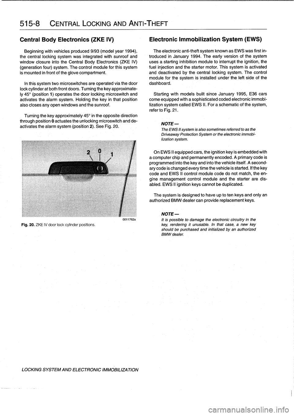
Turning
the
key
approximate-
ly
45°
(position
1)
operates
the
door
locking
microswitch
and
Startingwith
modeis
built
since
January
1995,
E36
cars
activates
the
alarm
system
.
Holding
the
key
in
thatposition
come
equipped
with
a
sophisticated
coded
electronic
immobi
also
closes
any
open
windows
and
the
sunroof
.
lization
system
called
EWS
II
.
Foraschematic
of
the
system,
refer
to
Fig
.
21
.
Turning
the
key
approximately
45°
in
the
opposite
direction
through
position
0
actuates
theunlocking
microswitch
and
de-
activates
the
alarm
system
(position
2)
.
See
Fig
.
20
.
NOTE
-
The
EWS
11
system
is
also
sometimes
referred
to
as
the
Driveaway
Protection
System
or
the
electronic
immobi-
lization
system
.
On
EWS
II
equipped
cars,
the
ignition
key
is
embedded
with
a
computer
chip
and
permanently
encoded
.
A
primary
code
is
programmed
into
the
keyand
finto
the
vehicle
itself
.
A
second-
ary
code
is
changed
every
time
the
vehicle
is
started
.
If
thekey
code
and
EWS
II
control
module
code
do
notmatch,
the
en-
gine
management
control
module
and
the
starter
are
dis-
abled
.
EWS
II
ignition
keyscannot
be
duplicated
.
The
system
is
designed
to
have
up
to
ten
keys
and
only
an
authorized
BMW
dealer
can
provide
replacement
keys
.
j
NOTE-
0011762a
ft
is
possible
to
damage
the
electronic
circuítry
in
the
Fig
.
20
.
ZKE
IV
door
lock
cylinder
positions
.
key,
rendering
if
unusable
.
In
that
case,
a
new
key
shouldbe
purchased
and
initialized
byan
authorized
BMW
dealer
.
LOCKING
SYSTEM
AND
ELECTRONIC
IMM081LIZATION
Page 383 of 759
NOTE
-
Sometimes
the
color
of
en
installed
wire
may
be
differ-
ent
than
the
one
on
the
wiring
diagram
.
Don't
be
con-
cerned
.
Just
be
sure
lo
confirm
that
the
wire
connects
lo
the
proper
terminals
.
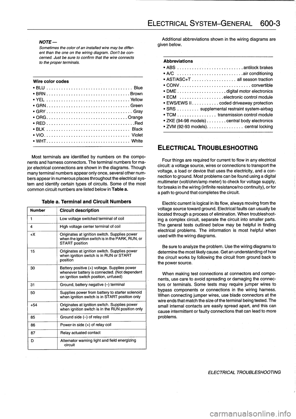
Wire
color
codes
"
BLU
.........
.
..
..
...
.
.................
Blue
"
BRN
....:....
.
..
..
...
..
...............
Brown
"
YEL
.........
.
..
..
...................
.Yellow
"
GRN
.........
.
..
..
...
.
................
creen
"
G
RY
.......
.
.
.
..
..
.....................
G
ray
"
ORG
.........
.
..
..
...
.
..............
.Orange
"
RED
......
...
.
.
..
.....................
.Red
"
BLK
.........
.
..
..
...
.
................
Black
"
VIO
..........
.
..
...
..
..
.......
.
.......
Violet
"
WHT
.........
.
.
....
.
...
:..............
White
Table
a
.
Terminal
and
Circuit
Numbers
Number
1
Circuít
description
1
j
Low
voltage
switched
terminal
of
coi¡
4
1
High
voltage
center
termina¡
of
coi¡
+x
Originates
atignition
switch
.
Supplies
powerwhen
the
ignition
switch
is
in
the
PARK,
RUN,
or
START
position
15
Originates
atignition
switch
.
Supplies
powerwhen
ignition
switch
is
in
RUN
or
START
position
30
Battery
positive
(+)
voltage
.
Supplies
power
whenever
battery
is
connected
.
(Not
dependent
on
ignition
switch
position,
unfused)
31
1
Ground,
battery
negative
(-)
terminal
50
Supplies
power
from
battery
to
starter
solenoid
when
ignition
switch
isin
START
position
only
+54
Originates
atignition
switch
.
Supplies
power
when
ignition
switch
isin
the
RUN
position
only
85
1
Ground
side
(-)
ofrelay
coil
86
1
Power-in
side
(+)
ofrelay
coil
87
1
Relay
actuatedcontact
D
Alternator
warning
light
and
field
energizing
circuit
ELECTRICAL
SYSTEM-GENERAL
600-
3
Additional
abbreviations
shown
in
the
wiring
diagrams
are
given
below
.
Abbreviations
"
ABS
........
.
...
.
...
.
..........
antilock
brakes
"
A/C
........
.
...
..
..
.
.........
.airconditioning
"
AST/ASC+T
.......
...
.
.
.......
al¡
season
traction
"
CONV
.......
.
.
...
.................
convertible
"
DME
........
.
.
...
.......
digital
motor
electronics
"
ECM
.......
.
...
..
..
.
..
electronic
control
module
"
EWS/EWS
II
......
...
.
.
coded
driveaway
protection
"
SRS
........
.
supplemental
restraint
system-airbag
"
TCM
........
.
..
....
.
transmission
control
module
"
ZKE
(94-98
models)
..
..
.
...
central
body
electronics
"
ZVM
(92-93
models)
...
.
.
..
.
.......
central
locking
ELECTRICAL
TROUBLESHOOTING
Most
terminals
are
identified
by
numbers
on
the
compo-
nents
and
harness
connectors
.
The
terminal
numbers
for
ma-
Four
things
are
required
for
current
toflow
in
any
electrical
jor
electrical
connections
are
shown
in
the
diagrams
.
Though
circuit
:
a
voltagesource,
wires
or
connections
to
transport
the
many
terminal
numbers
appear
only
once,
severa¡other
num-
voltage,
a
load
or
device
that
uses
the
electricity,
and
a
con-
bers
appear
in
numerous
places
throughout
the
electrical
sys-
nection
to
ground
.
Most
problemscanbefound
using
a
digital
tem
and
identify
certain
types
ofcircuits
.
Some
of
the
most
multimeter
(volt/ohm/amp
meter)to
check
for
voltage
supply,
common
circuit
numbers
are
listed
below
in
Table
a
.
for
breaks
in
the
wiring
(infinite
resistance/no
continuity),
orfor
a
path
to
ground
that
completesthe
circuit
.
Electric
current
is
logical
in
its
flow,
always
moving
from
the
voltage
sourcetoward
ground
.
Electricalfaults
can
usually
be
located
through
a
process
of
elimination
.
When
troubleshoot-
ing
a
complex
circuit,
separate
the
circuit
into
smaller
parts
.
The
general
testsoutlined
below
may
be
helpful
in
finding
electrical
problems
.
The
information
is
most
helpful
when
used
with
the
wiring
diagrams
.
Be
sure
to
analyze
the
problem
.
Use
the
wiring
diagrams
to
determine
the
most
likely
cause
.
Getan
understanding
of
how
the
circuit
works
by
following
the
circuit
from
groundback
to
the
power
source
.
When
making
test
connections
at
connectors
andcompo-
nents,
use
care
to
avoidspreading
or
damaging
the
connec-
tors
or
terminals
.
Some
tests
may
require
jumper
wires
to
bypass
components
or
connections
in
the
wiring
harness
.
When
connecting
jumper
wires,
use
bladeconnectors
at
the
wire
ends
that
match
the
size
of
the
terminal
being
tested
.
The
small
interna¡
contacts
are
easily
spread
apart,
and
this
can
cause
intermittent
or
faultyconnections
that
can
leadto
more
problems
.
ELECTRICAL
TROUBLESHOOTING
Page 387 of 759
610
Electrical
Component
Locations
GENERAL
...........
.
.
.
.
.
.
.
.
.
........
610-1
FOSE
POSITION
TABLES
..
.
.
.
.
.
.....
.
610-19
FUSE
AND
RELAY
POSITIONS
.
...
.
.
.
.
.
610-1
Fuse
Positions
.
.
.
................
.
.
.
.
.
610-1
Relay
Positions
.
.
.
.....
.
.
.
........
.
.
.
.
.
610-2
Auxiliary
RelayPanel
.....
.
...
.
........
.
610-2
SplicePanel,
Left
.
.
.
...
.
.
.
...
.
........
.
610-2
SplicePanel,
Right
.
.
.
.
.
.
.
.
...
.
.........
610-3
COMPONENT
LOCATIONS
.
.
.
.
.......
.
.610-3
Component
Location
Table
.
.
.
.
.
.
.........
610-9
GENERAL
FUSE
AND
RELAY
POSITIONS
This
repair
group
covers
f
use,
relay,
and
control
module
lo-
The
front
power
distribution
box,
an
auxiliary
relay
panel,cation
information
.
Electrical
equipment
and
accessories
in-
and
two
auxiliary
splice
panels
contain
most
of
the
fuses
and
stalled
varies
depending
on
model
and
model
year
.
Always
relays
in
E36
vehicles
.
Refer
to
the
component
location
later
confirm
that
the
proper
electrical
component
has
been
identi-
in
this
section,
as
well
as
the
tables
at
the
end
of
this
repair
fied
by
using
the
electrical
wiring
diagrams
.
group
for
electrical
component
location
.
WARNING
-
On
cars
equipped
with
airbags,
special
precautionsapply
to
any
electrical
system
testing
orrepair
.
Air-
bag
units
areexplosive
devices
and
mustbe
han-
dled
with
extremecare
.
Before
starting
any
work
onan
airbag
equipped
car,
refer
to
the
wamings
and
cautions
in
721
Airbag
System
(SRS)
.
CAUTION
-
"
Prior
to
disconnectiog
the
battery,
read
the
bat-
tery
disconnection
cautions
given
at
the
front
of
this
manual
on
page
viii
.
"
Relay
and
fuse
positions
are
subject
to
changeand
may
varyfrom
car
to
car
.
If
questions
arise,
an
authorized
BMW
dealer
is
the
best
source
for
the
most
accurate
and
up-to-date
information
.
"
A
good
way
to
verify
a
relay
position
isto
com-
pare
the
wiring
colors
at
the
relay
socket
to
thecolors
indicated
on
the
wiring
diagrams
located
at
the
rear
of
this
manual
.
"
Always
switchthe
ignition
off
and
disconnect
the
negative
(-)
battery
cable
before
removing
any
electrical
components
.
"
Connect
and
disconnect
ignition
system
wires,
multiple
connectors,
and
ignition
test
equipment
leads
only
while
the
ignition
is
switched
off
.
"
Only
usea
digital
multimeter
for
electrical
tests
.
ELECTRICAL
COMPONENT
LOCATIONS
610-1
TABLES
a
.
E36Component
Locations
...........
.
.
..
...
610-10b
.
1992
E36
Fuse
Positions
..........
..
.
.
.....
610-20c
.
1993
E36
Fuse
Positions
..........
..
..
.
....
610-22d
.
1994
E36
Fuse
Positions
.........
...
.......
610-24e
.
1995
E36
Fuse
Positions
.........
...
.......
610-26
f
.
1996
E36
Fuse
Positions
.........
...
.......
610-28g
.
1997-1998
E36
Fuse
Positions
..
.
..
...
.......
610-30
Fuse
Positions
CAUTION
-
"
Replace
fuses
with
those
of
the
same
rating
.
In-
stalling
a
fuse
with
higher
rating
can
lead
to
cir-
cuit
failure
and
may
also
start
a
fire
.
"
Relay/fuse
positions
vary
by
model
and
equip-
ment
.
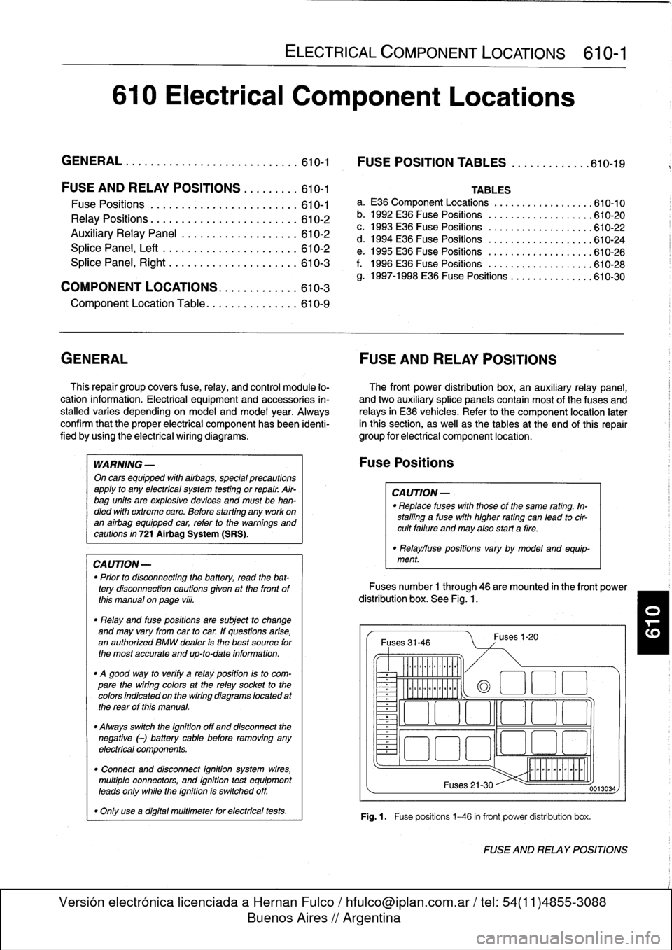
Fuses
number
1
through
46
are
mounted
in
the
front
power
distribution
box
.
See
Fig
.
1.
Fuses
31-46
~
Illlllllllll
°
-
Ilmmlmomlmoi
Fuses
1-20
(a
1
:1
E
El
~
~O!7
L~~n
4~
i
Fuses
21-30
Fig
.1.
Fuse
positions
1-46
in
front
power
distribution
box
.
0013034
FUSE
AND
RELAY
POSITIONS