BMW M3 1998 E36 Workshop Manual
Manufacturer: BMW, Model Year: 1998, Model line: M3, Model: BMW M3 1998 E36Pages: 759
Page 441 of 759
FRONT
LIGHTING
.
...........
.
....
.
.
.
.
630-1
Headlight
buib,
replacing
............
.
.
.
.
630-1
Headlight
assembly,
removing
and
installing
.......
.
....
.
.
.
.
630-2
Foglight
assembly,
removing
and
installing
..
630-3
Front
turn
signal
assembly,
removing
and
installing
.....
.
.
.
........
630-4
GENERAL
The
headlight
and
foglight
assemblies
usehalogen
bulbs
.
To
ensure
the
longevity
of
halogen
bulbs,
the
bulb
glass
should
not
be
handied
.
Dirt
and
skin
oíls
may
cause
a
bulbto
fail
prematurely
.
If
necessarywipe
bulb
using
a
clean
cloth
dampened
with
rubbing
alcohol
.
NOTE-
Use
only
original
equipment
replacement
bulbs
.
Non-
original
equipment
bulbs
may
cause
false
failure
read-
ings
on
the
check
control
display
(where
applicable)
.
WARNING
-
INhenworking
on
electrical
systems,
remove
the
fuse
protecting
the
circuit
under
repair
.
See
610
Electrical
Component
Locations
.
FRONT
LIGHTING
Headlight
bulb,
replacing
1
.
Open
engine
hood
.
2
.
Working
in
back
of
headlight
assembly,grasp
rear
of
bulbsocket
(harnessconnector)
and
turn
counterclock-
wise
90°
.
Pull
bulb
out
of
headlight
assembly
.
See
Fig
.
1
.
3
.
Disconnect
harness
connector
from
bulb
.
CA
UTION-
Do
not
touch
halogen
bubs
with
yourbare
hands
.
If
necessary
wipe
bulb
using
a
clean
cloth
damp-
ened
with
rubbing
alcohol
.
630
Exterior
Lighting
EXTERIOR
LIGHTING
630-1
GENERAL
.
.
.
.
...
.
................
.
.
.
.
630-1
Side
Marker
Lights
.......
.
.
.
.
.
.......
.
..
630-4
REAR
LIGHTING
.
......
.
.
.
.
.
.
.
...
.
.
.
..
630-4
Taillight
Bulbs
..........
.
.
.
.
.
.....
.
.
.
.
.
630-4
Taillight
assembly,
removing
and
installing
.
.
.
630-5
CenterBrake
Light
.......
.
.
.
.
.
.
.
.
.
.
.
.
.
.
.
630-5
Center
brake
light
housing,
replacing
(4-door
and
coupe
models)
.
.
.
.
.......
.
.
.630-5
License
plate
light,
removingand
installing
.
.630-6
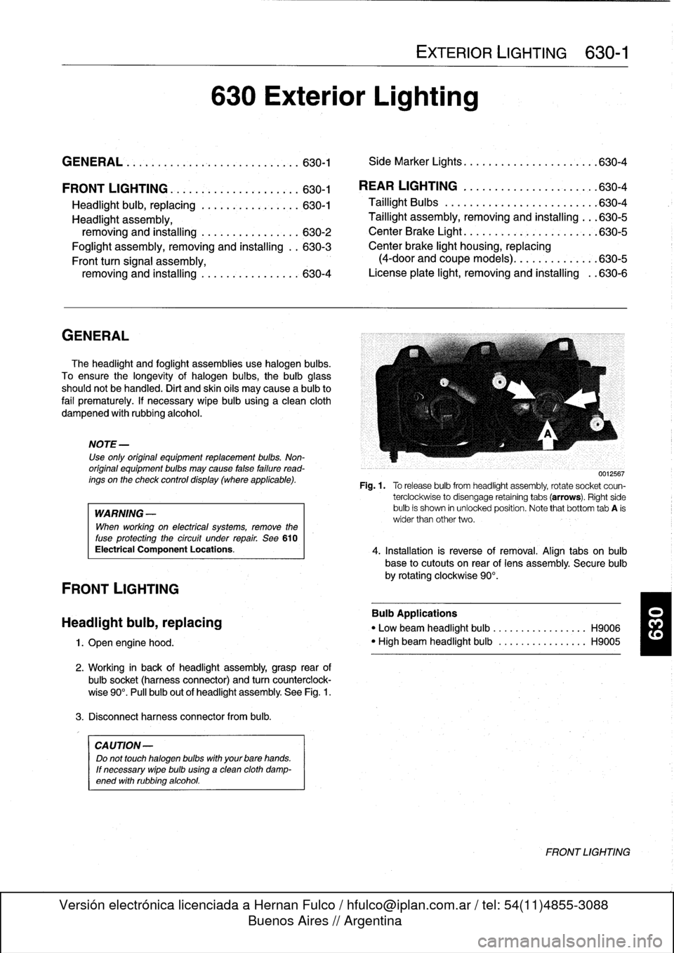
0012567
Fig
.1.
Torelease
bulbfrom
headlight
assembly,
rotate
socket
coun-
terclockwise
to
disengage
retaining
tabs
(arrows)
.
Right
side
bulb
is
shown
in
unlocked
position
.
Note
that
bottom
tab
A
is
wider
than
other
two
.
4
.
Installation
is
reverse
of
removal
.
Align
tabs
on
bulb
base
to
cutouts
on
rear
of
lens
assembly
.
Secure
bulb
by
rotating
clockwise
90°
.
Bulb
Applications
"
Low
beam
headlight
bulb
...
.
..
..
.........
H9006
"
High
beam
headlight
bulb
..
.
..
..
.........
H9005
FRONT
LIGHTING
Page 442 of 759
630-2
EXTERIOR
LIGHTING
Headlight
assembly,
removing
and
installing
CAUTION-
Followingheadlight
assembly
work
headlight
beam
aim
must
be
adjusted
using
special
equip-
ment
.
1
.
Left
side
:
Remove
air
filter
housing,
air
intake
duct,
and
air
mass
meter
.
See
100
Engine-General
.
2
.
Disconnect
harness
connectors
from
headlight
bulbs
.
3
.
Remove
front
turn
signal
.
See
Front
turn
signal
as-
sembly,
removingand
installing
later
in
this
repair
group
.
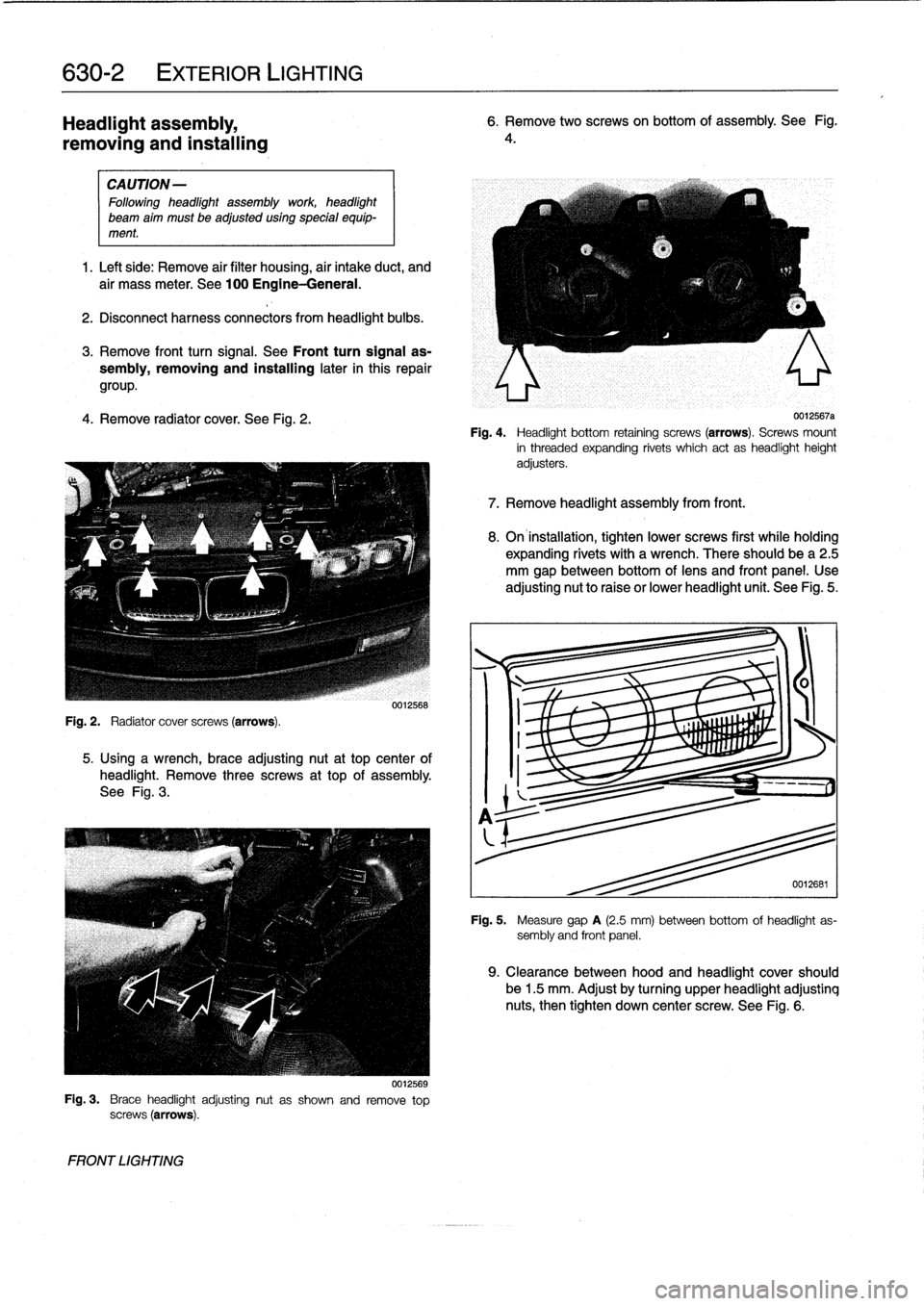
4
.
Remove
radiator
cover
.
See
Fig
.
2
.
5
.
Using
a
wrench,
brace
adjusting
nut
at
top
center
of
headlight
.
Remove
three
screws
at
top
of
assembly
.
See
Fig
.
3
.
Fig
.
3
.
Brace
headlightadjustingnut
as
shown
and
remove
top
screws
(arrows)
.
FRONT
LIGHTING
0012568
0012569
6
.
Remove
two
screwson
bottom
of
assembly
.
See
Fig
.
4
.
0012567a
Fig
.
4
.
Headlight
bottom
retaining
screws
(arrows)
.
Screws
mount
in
threaded
expanding
rivets
which
act
as
headlightheight
adjusters
.
7
.
Remove
headlight
assembly
from
front
.
8
.
On
installation,
tighten
lower
screws
first
while
holding
expanding
rivets
with
a
wrench
.
There
should
be
a
2
.5
mm
gap
between
bottom
oflens
and
front
panel
.
Use
adjusting
nut
to
raise
or
lower
headlight
unit
.
See
Fig
.
5
.
0012681
Fig
.
5
.
Measure
gap
A
(2.5
mm)
between
bottom
of
headlight
as-
sembly
and
front
panel
.
9
.
Clearance
between
hood
and
headlight
cover
should
be
1
.5
mm
.
Adjust
by
turning
upper
headlight
adjustinq
nuts,
then
tighten
down
center
screw
.
See
Fig
.
6
.
Page 443 of 759
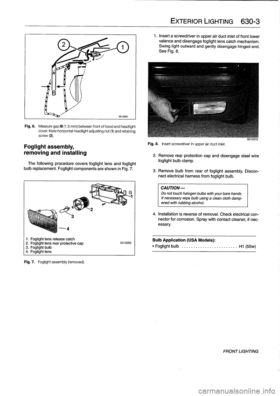
4
Foglight
assembly,
removing
and
installing
1
.
Foglight
lens
release
catch
2
.
Foglight
lensrear
protective
cap
3
.
Foglight
bulb
4
.
Foglight
lens
Fig
.
7
.
Foglight
assembly
(removed)
.
0012682
Fig
.
6
.
Measure
gap
B
(1.5
mm)
between
front
of
hood
and
headlight
cover
.
Note
horizontal
headlightadjusting
nut
(1)
and
retaining
screw
(2)
.
The
following
procedure
covers
foglight
lens
and
foglight
buib
replacement
.
Foglight
components
are
shown
in
Fig
.
7
.
0012683
EXTERIOR
LIGHTING
630-
3
1
.
Insert
a
screwdriver
in
upper
air
duct
inlet
of
front
lower
valence
and
disengage
foglight
lens
catch
mechanism
.
Swing
light
outward
and
gently
disengage
hinged
end
.
See
Fig
.
8
.
Fig
.
8
.
Insert
screwdriver
in
upper
air
duct
inlet
.
uu¡¿biu
2
.
Remove
rear
protection
capand
disengage
steel
wire
foglight
bulb
clamp
.
3
.
Remove
bulb
from
rear
of
foglight
assembly
.
Discon-
nect
electrical
harness
from
foglight
bulb
.
CAUTION
-
Do
not
touch
halogen
bulbs
with
yourbare
hands
.
If
necessary
wipe
buib
using
a
clean
cloth
damp-ened
withrubbing
alcohol
.
4
.
Installation
is
reverse
of
removal
.
Check
electrical
con-nector
for
corrosion
.
Spray
with
contact
cleaner,
if
nec-
essary
.
Bulb
Application
(USA
Models)
:
"
Foglight
bulb
......
...
..
...
..........
Hl
(55w)
FRONT
LIGHTING
Page 444 of 759
630-
4
EXTERIOR
LIGHTING
Front
turn
signal
assembly,
Side
Marker
Lights
removing
and
installing
Side
marker
lights
on
later
model
E36
cars
are
snapped
into
The
procedurebelow
also
includes
turn
signal
bulb
replace-
the
front
fenders
.
To
service,
carefully
pry
the
assembly
out
of
ment
.
the
fender,
then
detach
the
electrical
harness
connector
and
bulb
socket
.
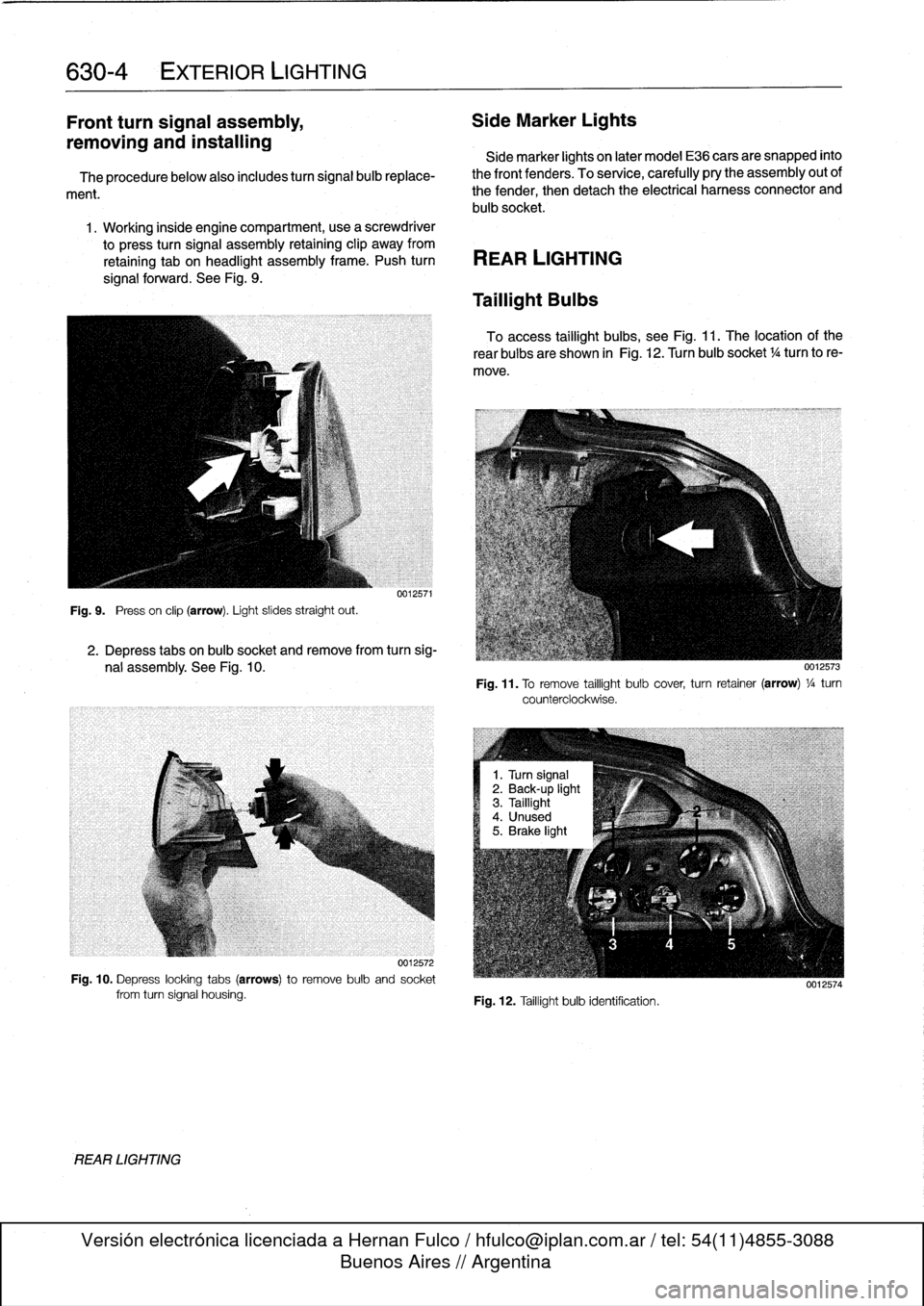
1
.
Working
inside
engine
compartment,usea
screwdriver
to
press
turn
signal
assembly
retaining
clip
away
from
retaining
tab
on
headlight
assembly
frame
.
Push
turn
REAR
LIGHTING
signal
forward
.
See
Fig
.
9
.
Fig
.
9
.
Press
on
clip
(arrow)
.
Light
slides
straight
out
.
REAR
LIGHTING
0012571
2
.
Depress
tabs
on
bulb
socket
and
remove
from
turn
sig-
nal
assembly
.
See
Fig
.
10
.
0012572
Fig
.
10
.
Depress
locking
tabs
(arrows)to
remove
bulb
and
socket
from
turn
signal
housing
.
Taillight
Bulbs
To
access
taillight
bulbs,
see
Fig
.
11
.
The
location
of
the
rear
bulbs
are
shown
in
Fig
.
12
.
Turn
bulb
socket
1
/4turn
to
re-
move
.
Fig
.
11
.
To
remove
taillight
bulb
cover,
turn
retainer
(arrow)
1
/a
turn
counterclockwise
.
Fig
.
12
.
Taillight
bulb
identification
.
0012574
Page 445 of 759
Taillight
assembly,
removing
and
installing
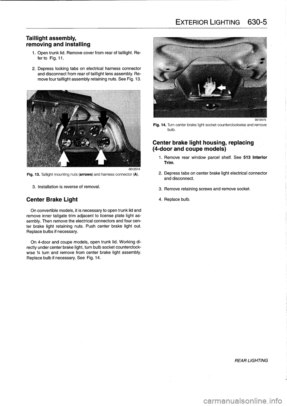
1
.
Open
trunk
lid
.
Remove
cover
from
rear
of
taillight
.
Re-
fer
to
Fig
.
11
.
2
.
Depress
locking
tabs
on
electrical
harness
convector
and
disconnect
from
rear
of
taillight
lens
assembly
.
Re-
move
four
taillight
assembly
retaining
nuts
.
See
Fig
.
13
.
0012574
Fig
.
13
.
Taillight
mounting
nuts
(arrows)
and
harness
connector
(A)
.
3
.
Installation
is
reverse
of
removal
.
Center
Brake
Light
On
convertible
models,
it
is
necessary
to
open
trunk
lid
and
remove
inner
tailgatetrim
adjacent
to
license
plate
light
as-
sembly
.
Then
remove
the
electrical
connectors
and
four
cen-
ter
brake
light
retaining
nuts
.
Push
center
brake
light
out
.
Replace
bulbs
if
necessary
.
On
4-door
and
coupe
models,
open
trunk
lid
.
Working
di-
rectly
under
center
brake
light,
turn
bulb
socket
counterclock-
wise
1
/4turn
andremove
from
center
brake
light
assembly
.
Replace
bulb
if
necessary
.
See
Fig
.
14
.
EXTERIOR
LIGHTING
630-
5
0012575
Fig
.
14
.
Turncenter
brake
light
socket
counterclockwise
and
remove
bulb
.
Center
brake
light
housing,
replacing
(4-door
andcoupe
models)
1
.
Remove
rear
window
parcel
shelf
.
See513
Interior
Trim
.
2
.
Depress
tabs
on
center
brake
light
electrical
connector
and
disconnect
.
3
.
Remove
retaining
screws
and
remove
socket
.
4
.
Replace
bulb
.
REAR
LIGHTING
Page 446 of 759
630-
6
EXTERIOR
LIGHTING
License
plate
light,
removing
and
installing
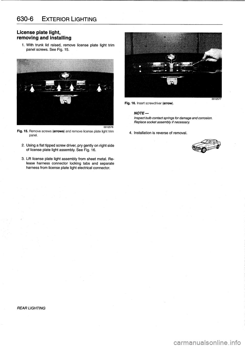
1
.
With
trunk
lid
raised,
remove
lícense
plate
light
trim
panel
screws
.
See
Fig
.
15
.
0012576
Fig
.
15
.
Remove
screws
(arrows)
and
remove
license
plate
light
trim
panel
.
2
.
Using
a
flat
tipped
screw
driver,
pry
gently
on
right
side
of
license
plate
light
assembly
.
See
Fig
.
16
.
3
.
Lift
license
plate
light
assembly
from
sheetmetal
.
Re-
lease
harness
connector
locking
tabs
and
separate
harness
from
license
plate
light
electrical
connector
.
REAR
LIGHTING
Fig
.
16
.
Insert
screwdriver
(arrow)
.
NOTE
-
Inspect
bulb
contactsprings
for
damageand
corrosión
.
Reptace
socket
assembly
if
necessary
.
4
.
Installatíon
is
reverse
of
removal
.
0012577
Page 447 of 759
GENERAL
E36
cars
are
equipped
with
integrated
automatic
heating
and
air
conditioning
systems
.
Many
of
the
procedures
given
in
this
repair
group
require
that
the
A/C
refrigerant
charge
be
evacuated
using
specialized
equipment
.
See
A/C
System
Warningsand
Cautions
later
in
this
repair
group
.
HEATER
AND
CONTROLS
Blower
motor,
removing
and
installing
NOTE-
On
6-cylinder
cars,
the
plastic
top
enginecover
and
fuel
rail
covermustbe
removed
.
The
fuel
injectorhamess
re-
taining
screws
must
be
removed
and
the
harness
set
aside
.
The
engine
control
module
(ECM)
cover
must
be
removed,
the
control
unit
connectors
unplugged
and
the
harness
pulled
out
of
the
way
.
See
130
Fuel
Injection
.
1
.
Disconnect
negative
(-)
cable
from
battery
.
2
.
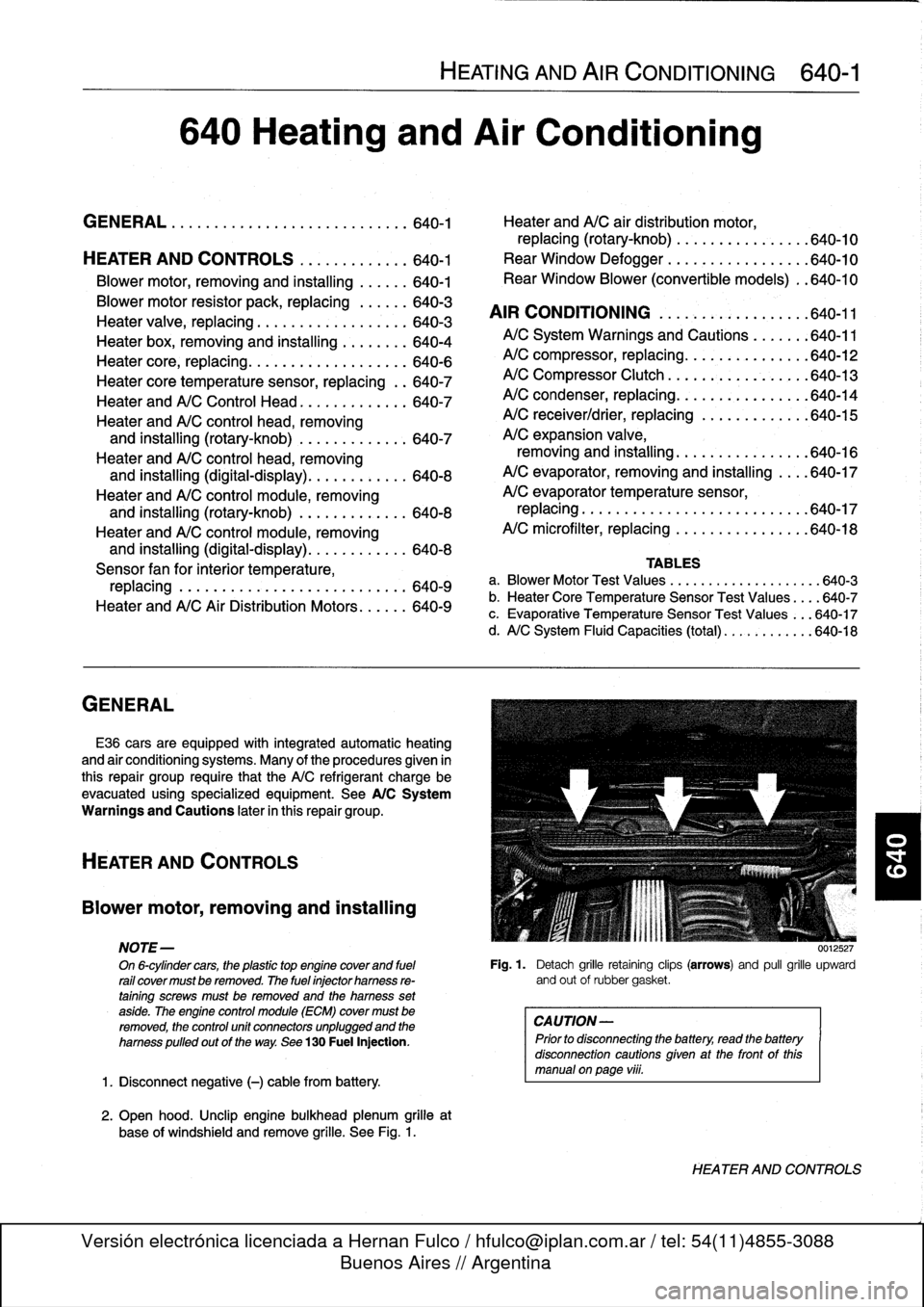
Open
hood
.
Unclip
engine
bulkhead
plenum
grille
at
base
of
windshíeld
and
remove
grille
.
See
Fig
.
1
.
HEATING
AND
AIR
CONDITIONING
640-1
640
Heating
and
Air
Conditioning
GENERAL
.
...
.
....
.
.
.
.
.
.
.
.
.
.......
.
.
.
640-1
Heater
andA/C
air
distribution
motor,
replacing(rotary-knob)
.
.
...
.
.
.
.......
.
640-10
HEATER
AND
CONTROLS
.
.....
.
.
.
.
.
.
.640-1
Rear
Window
Defogger
.
.
.
.
.
.
.
.
.
.
...
.
.
.
640-10
Blower
motor,
removing
and
installing
.
.
.
.
.
.
640-1
Rear
Window
Blower
(convertible
models)
.
.640-10
Blowermotor
resistor
pack,
replacing
.
.
.
.
.
.
640-3
AIR
CONDITIONING
.
.
.
.
.
.
.
.
.
.
.
.
.
.
.
.
.
.
640-11
Heater
valve,
replacing
...........
.
.
.
.
.
.
.
640-3
Heater
box,
removing
and
installing
.
.
.
.
.
.
.
.
640-4
A/CSystem
Warnings
and
Cautions
.
.
.
.
.
.
:640-11
Heater
core,
replacing
.....
.
.
:
....
.
.
.
.
.
.
.
640-6
A/C
compressor,
replacing
.
.
::.
:
:
.
.
.
.
.
.
.
.640-12
Heater
core
temperature
sensor,
replacing
.
.
640-7
A/C
Compressor
Clutch
.
.
.
.
.
.
.
:
.
.
.
.
.
.
.
.
.
640-13
Heater
andA/C
Control
Head
.
.
....
.
.....
.
640-7
A/C
condenser,
replacing
.
.
.
.
.
.
.
.
.
.
.
.
.
.
.
.
640-14
Heater
andA/C
control
head,
removing
A/C
receiver/drier,
replacing
.
.
.
.
.
.
.
.
.
.
.
.
.
640-15
and
installing
(rotary-knob)
.
.
....
.
......
640-7
A/C
expansion
valve,
Heater
andA/C
control
head,
removing
removing
and
installing
...
.
.....
.
.
.
.
.
.
.
640-16
and
installing
(digital-display)
.
.....
.
.....
640-8
A/C
evaporator,
removing
and
installing
.
.
..
640-17
Heater
andA/C
control
module,removing
A/C
evaporator
temperature
sensor,
and
installing
(rotary-knob)
.
.
...
.
.
.
.
.
.
.
.
640-8
replacing
.
.
.
.
.
.
..............
.
.
.
.
.
..
640-17
Heater
andA/C
control
module,removing
A/C
microfilter,
replacing
......
.
....
.
.
.
..
640-18
and
installing
(digital-display)
.
...
.
.
.
.
.
...
640-8
Sensor
fan
for
interior
temperature,
TABLES
replacing
.
.
.
....
.
.
.
.
.
.
.
.
.
.
.
.
.
.
.
.
.
.
.
.
640-9
a
.
Blower
Motor
Test
Values
.........
...
.
.
......
640-3
Heater
andA/C
AirDistribution
Motors
.
.
.
.
.
.
640-9
b
.
Heater
Core
Temperature
Sensor
Test
Values
...
.640-7
c
.
Evaporative
Temperature
Sensor
Test
Values
...
640-17
d
.
A/C
System
Fluid
Capacities
(total)
..
..........
640-18
0012527
Fig
.
1
.
Detach
grille
retaining
clips
(arrows)
and
pull
grille
upward
and
out
of
rubbergasket
.
CAUTION-
Prior
to
disconnectiog
the
battery,
read
the
battery
disconnection
cautionsgiven
at
the
front
of
this
manual
onpage
viii
.
HEATER
AND
CONTROLS
Page 448 of 759
640-2
HEATING
AND
AIR
CONDITIONING
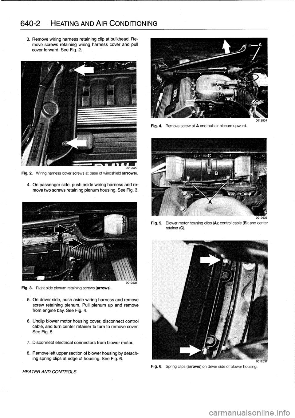
3
.
Remove
wiring
harness
retaining
clip
at
bulkhead
.
Re-
move
screws
retaining
wiring
harness
cover
and
pull
cover
forward
.
See
Fig
.
2
.
0012529
Fig
.
2
.
Ming
harness
cover
screws
at
base
ofwindshield
(arrows)
.
4
.
On
passenger
side,
push
aside
wiring
harness
and
re-
move
two
screws
retaining
plenum
housing
.
See
Fig
.
3
.
Fig
.
3
.
Ríghtside
plenum
retaining
screws
(arrows)
.
VU1L535
5
.
On
driverside,
push
aside
wiring
harness
and
remove
screw
retaining
plenum
.
Pull
plenum
up
and
remove
from
engine
bay
.
See
Fig
.
4
.
6
.
Unclip
blower
motor
housing
cover,
disconnect
control
cable,
and
turn
center
retainer
1
/4
turn
to
remove
cover
.
See
Fig
.
5
.
7
.
Disconnect
electrical
connectors
from
blower
motor
.
8
.
Remove
left
upper
section
of
blower
housingby
detach-
ing
spring
clipsat
edge
of
housing
.
See
Fig
.
6
.
HEATER
AND
CONTROLS
Fig
.
4
.
Remove
screw
at
A
and
pull
air
plenumupward
.
0012534
0012636
Fig
.
5
.
Blower
motor
housing
clips
(A)
;
control
cable
(B)
;
and
center
retainer(C)
.
i
[u6,
Fig
.
6
.
Spring
clips
(arrows)
on
driver
sideof
blower
housing
.
Page 449 of 759
9
.
Release
blower
motor
retaining
strap
andremove
blow-
er
motor
and
fans
fromcowl
opening
.
NOTE-
Twist
and
rotate
blowermotor
assembly
to
facilítate
re-
moval
from
opening
.
If
the
blower
motor
is
to
be
rein-stafled,
use
care
not
to
damage
fan
wheels
during
removal
.
ff
the
blower
motor
fs
to
be
replaced,
cut
offfan
wheels
at
center
to
aid
in
removal
.
10
.
Installation
is
reverse
of
removal
.
When
installing
a
re-
placement
blower
motor,
instan
motor
into
cowlarea
before
installing
fan
wheels
.
Blower
motor
test
specifi-
cations
are
listed
in
Table
a
.
NOTE
-
On
replacementblowermotors
from
BMW,
thefan
wheels
come
unattached
to
aid
in
installation
.
Locatearrow
on
blower
motor
and
instan
fan
wheels
atthis
po-
sition
.
Be
sure
color
coolng
matches
.
Retain
fan
wheels
using
the
new
clips
.
See
an
authorized
BMW
parts
de-
partment
for
the
latest
parts
information
.
Table
a
.
Blower
Motor
Test
Values
Testingvoltage
13
VDC
Operating
voltage
9-15
VDC
Max
.
current
consumption
(approx
.)
12
amps
Maximum
speed
3,600-4,000rpm
Axialplay
(max
.
allowable)
1
.0
mm
(0
.04
in
.)
Blower
motor
resistor
pack,
replacing
The
blower
resistor
pack
is
clipped
into
the
upper
left
side
of
theheater
box
.
1
.
Remove
lower
left
dash
trim
panel
.
See513
Interior
Trim
.
2
.
Working
under
left
(driver's)
side
of
dash,
unclip
and
pulí
out
resistor
pack
from
sideof
heater
box
.
Remove
harness
connector
from
resistor
pack
.
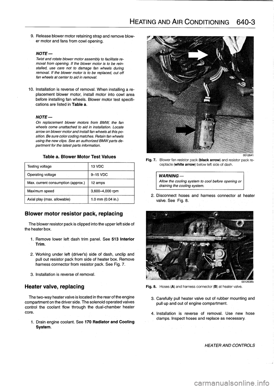
See
Fig
.
7
.
3
.
Installation
is
reverse
of
removal
.
Heater
valve,
replacing
The
two-way
heater
valve
is
located
in
the
rear
of
the
engine
compartment
on
the
driver
side
.
The
solenoid
operated
valves
control
the
coolant
flow
through
the
dual-chamber
heater
core
.
1
.
Drain
engine
coolant
.
See
170
Radiator
and
Cooling
System
.
HEATING
AND
AIR
CONDITIONING
640-
3
uuiGO4I
Fig
.
7
.
Blower
fan
resistor
pack
(black
arrow)
and
resistor
pack
re-
ceptacle
(white
arrow)
below
left
sideof
dash
.
WARNING
-
Allow
the
cooling
system
to
cool
before
opening
ordraining
the
cooling
system
.
2
.
Disconnect
hoses
and
harness
connector
at
heater
valve
.
See
Fig
.
8
.
001[ó38b
Fig
.
S
.
Hoses
(A)
and
harnessconnector
(B)
at
heatervalve
.
3
.
Carefully
pull
heater
valve
out
of
rubber
mounting
and
pull
up
and
out
of
engine
compartment
.
4
.
Installation
is
reverse
of
removal
.
Use
new
hose
clamps
.
Inspect
hoses
and
replace
asnecessary
.
HEATER
AND
CONTROLS
Page 450 of 759
640-4
HEATING
AND
AIR
CONDITIONING
Heater
box,
removing
and
installing
The
heater
box,
located
underneath
thecenter
of
the
dash-
board,
houses
theheater
core,
the
A/C
evaporator,
and
asso-
ciated
sensors
and
actuators
.
Removal
of
theheater
box
requires
that
the
A/C
refrigerant
be
discharged
.
CAUTION-
"
Removing
the
heater
box
requires
evacuating
the
AIC
system
.
DO
NOT
attempt
this
procedure
without
proper
tools
and
training
.
"
Any
person
who
services
a
motor
vehicle
air
con-
ditioner
must,
by
law,
be
properly
trained
and
cer-
tified,
and
use
approved
refrigerant
recycling
equipment
.
Technicians
must
complete
an
EPA-
approved
recycling
course
to
be
certified
UU12639
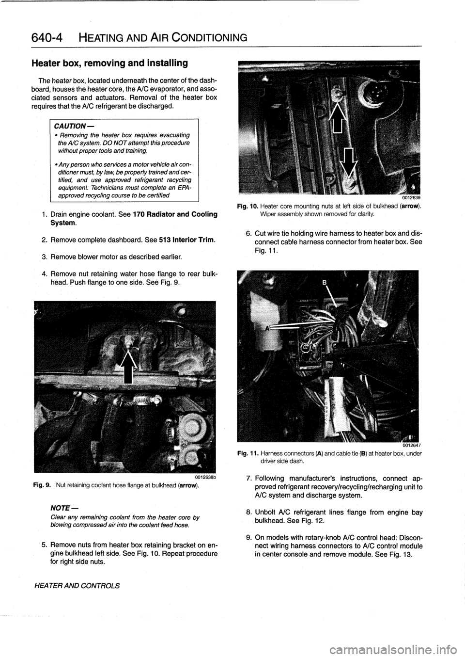
Fig
.
10
.
Heater
core
mounting
nuts
at
left
sideof
bulkhead
(arrow)
.
1
.
Drain
engine
coolant
.
See
170
Radiator
and
Cooling
wiper
assembly
shown
removed
for
clarity
.
System
.
2
.
Remove
complete
dashboard
.
See513
Interior
Trim
.
3
.
Remove
blower
motoras
described
earlier
.
4
.
Remove
nut
retaining
water
hose
flange
to
rear
bulk-
head
.
I'ush
flange
to
one
side
.
See
Fig
.
9
.
Fig
.
9
.
Nut
retaining
coolant
hose
flangeat
bulkhead
(arrow)
.
NOTE-
Clear
any
remaining
coolant
from
the
heater
core
by
blowing
compressed
air
finto
the
coolant
feed
hose
.
HEATER
AND
CONTROLS
0012638b
6
.
Cut
wire
tie
holding
wire
harness
to
heater
box
and
dis-
connect
cable
harness
connector
from
heater
box
.
See
Fig
.
11
.
0012647
Fig
.
11
.
Harness
connectors
(A)
and
cable
tie
(B)
at
heaterbox,
under
driver
side
dash
.
7
.
Followingmanufacturer's
instructions,
connect
ap-
proved
refrigerant
recovery/recycling/recharging
unitto
A/C
system
and
discharge
system
.
8
.
Unbolt
A/C
refrigerantlines
flange
from
engine
bay
bulkhead
.
See
Fig
.
12
.
9
.
On
models
with
rotary-knob
A/C
control
head
:
Discon-
5
.
Remove
nuts
from
heater
box
retaining
bracket
on
en-
nect
wiring
harness
connectors
to
A/C
control
module
gine
bulkhead
left
side
.
See
Fig
.
10
.
Repeat
procedure
in
center
console
and
remove
module
.
See
Fig
.
13
.
for
right
side
nuts
.