fuse box diagram BMW M3 1998 E36 Workshop Manual
[x] Cancel search | Manufacturer: BMW, Model Year: 1998, Model line: M3, Model: BMW M3 1998 E36Pages: 759
Page 155 of 759
Oxygen
Sensor
FUEL
DELIVERY
TESTS
FUEL
INJECTION
130-
9
"
Voltage
at
¡dle
..
.
..
..
....
0
.2
to
0
.8
VDC,
fluctuating
Checking
fuel
delivery
is
afundamental
part
of
trouble-
shooting
and
diagnosing
the
engine
management
system
.
Fuel
pressure
directly
influences
fuel
delivery
.
An
accurate
NOTE-
fuel
pressure
gauge
will
be
needed
to
make
the
tests
.
To
check
sensorresponse
to
lean
and
rich
mixtures,
createenairleak,
orpull
vacuumhoseofffue¡
pressure
There
are
three
significant
fuel
delivery
values
to
be
mea-
regulator
to
increase
fuel
pressure
.
sured
:
3
.
Separate
sensorharness
connector
from
sensor
.
Check
for
battery
voltage
between
terminals
3
and
4
(green
wire
and
brown
wire)
in
main
wiring
harness
side
of
con-
nector
with
engine
running
.
If
voltage
is
not
present,
check
oxygen
sensor
heater
relay
.
See610
Electrical
Component
Locations
.
4
.
Check
heater
element
resistance
between
terminals
3
and
4
in
sensor
side
of
connector
.
If
element
is
electri-
cally
open
(no
continuity),
replace
sensor
.
NOTE-
The
oxygen
sensor
heater
relay
is
mounted
in
the
main
power
distributfon
box
in
the
left
rear
of
the
engine
com-
partment
.
Refer
to
Fig
.
6
.
The
heater
relay
is
energized
wíth
positive
(+)
battery
voltage
from
the
main
relayanda
switched
ground
from
the
ECM
.
See
Electrical
Wir-
ing
Diagrams
.
"
Oxygen
sensor
to
exhaust
pipe
...
..
55
Nm
(41
ft-Ib)
"
System
pressure-created
by
the
fuel
pump
and
main-
tained
by
the
pressure
regulator
.
"
Fuel
delivery
volume-created
by
the
fuel
pump
and
af-
fected
by
restrictions,
suchasclogged
fuel
filter
.
"
Residual
pressure-the
pressure
maintained
in
the
closed
system
after
the
engine
and
fuel
pump
are
shut
off
.
Procedures
for
measuring
the
first
two
quantities
arede-
scribed
in
160
Fuel
Tank
and
Fuel
Pump
.
Residual
fuel
pres-
sure
is
checked
using
the
procedure
detailed
later
in
this
group
.
Operating
fuel
pump
fortests
To
operate
the
fuel
pump
for
testing
purposes
without
hav-
íng
to
runthe
engine,
the
fuel
pump
relay
can
be
bypassed
to
power
the
pump
directly
.
Fuel
pump
relay
location
is
shown
in
Fig
.
6
.
5
.
¡f
oxygen
sensor
doesn't
produce
a
fluctuating
voltage
To
runthe
fuel
pump,
remove
the
fuel
pump
relay
and
con-
and
preheater
circuit
is
OK,
replace
sensor
.
nect
the
socket
for
relayterminal
30
to
the
socket
for
relay
ter-
mina¡
87
with
a
fused
jumper
wire
.
After
completing
the
tests,
NOTE-
remove
the
jumper
wire
.
If
not
already
applied,
coat
the
oxygen
sensor
threads
with
an
anti-seize
compound
before
installation
.
Do
not
CAUTION-
getthe
compound
on
the
sensor
tip
.
"
Relay
locations
may
vary
.
Use
care
when
identi-
fying
relays
and
making
electrical
checks
at
the
fuselrelay
panel
.
See
610
Electrical
Compo
Tightening
Torque
nent
Locations
for
additional
relay
information
.
"
The
fuel
pump
relay
has
a
1
.5
mm2
red
wire
at
ter-
minal
30
in
the
relay
socket
.
Terminal
87
has
a
1
.5
mm
2
greenlviolet
wire
.
See
Electrical
Wiring
Di-
agrams
for
additional
wiring
information
.
NOTE-
Thejumper
wire
should
be
1.5
mm2
(14
ga
.)
and
in-
clude
an
in-line
tuse
holder
with
a15
amp
tuse
.
To
avoid
fuselrelay
panel
damage
from
repeated
connect-
ing
and
disconnecting,
also
include
a
toggle
switch
.
A
heavy-duty
jumper,
BMW
tool
no
.
61
3
050,
is
also
available
from
an
authorized
BMW
dealer
.
FUEL
DELIVERYTESTS
Page 173 of 759
0013ZIM
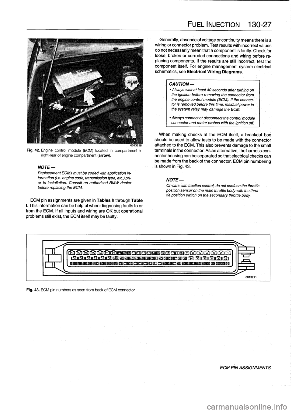
Fig
.
42
.
Engine
control
module
(ECM)
located
in
compartment
in
right-rearof
engine
compartment
(arrow)
.
NOTE-
Replacement
ECMs
must
be
coded
with
application
in-
formation
(Le
.
engine
code,
transmission
type,
etc
.)
pri-
or
to
installation
.
Consult
an
authorized
BMW
dealer
before
replacing
the
ECM
.
ECM
pin
assignments
are
given
in
Tables
h
through
Table
I.
This
information
can
be
helpful
when
diagnosing
faultsto
or
from
the
ECM
.
If
al¡
inputs
and
wiring
are
OK
butoperational
problems
still
exist,
the
ECM
itself
may
be
faulty
.
Fig
.
43
.
ECM
pin
numbers
as
seen
from
back
of
ECM
connector
.
FUEL
INJECTION
130-
2
7
Generally,
absence
of
voltage
or
continuity
means
there
is
a
wiring
or
connector
problem
.
Test
results
with
incorrect
values
do
notnecessarily
mean
that
a
component
is
faulty
:
Check
for
loose,
broken
or
corroded
connections
and
wiring
before
re-
placing
components
.
If
the
results
are
still
incorrect,
test
the
component
itself
.
For
engine
management
system
electrical
schematics,
see
Electrical
Wiring
Diagrams
.
CAUTION-
Always
waitat
least
40
seconds
after
tuniing
off
the
ignition
before
removing
the
connector
from
the
engine
control
module
(ECM)
.
If
the
connec-
tor
is
removed
before
this
time,
residual
power
in
the
system
relay
may
damage
the
ECM
.
"
Always
connector
disconnect
the
control
module
connector
and
meter
probes
with
the
ignitionoff
.
When
making
checks
at
the
ECM
itself,
a
breakout
box
should
be
used
to
allow
tests
to
be
made
with
the
connector
attached
to
the
ECM
.
This
also
prevents
damage
tothe
small
termínals
in
the
connector
.
As
an
alternative,
theharness
con-
nector
housing
can
be
separated
so
that
electrical
checks
can
be
made
from
the
back
of
the
connector
.
ECM
pin
numbering
is
shown
in
Fig
.
43
.
NOTE
-
On
cars
with
tractioncontrol,
do
not
confuse
the
throttle
position
sensor
on
the
main
throttle
body
with
the
throt-
tle
position
switch
on
the
secondary
throttle
body
.
27
Lb
2L4
LJ
22
©©®®17
©©®©©~©©®©~~rui~~ru
®®®®®®®®®®®®®®®IZA®®®®®®®®®®®®®®®®®
1
>I-
0013211
ECM
PIN
ASSIGNMENTS
Page 191 of 759
Fig
.
9
.
Fuel
pump
relay
terminal
identification
.
Fuel
Pump
Electrical
Tests
Troubleshooting
of
any
fuel
pump
fault
should
begin
with
checking
the
fuel
pump
fuse
and
the
fuel
pump
relay
.
The
DME
main
relay
should
also
be
checked
.
NOTE-
Special
tools
are
requíred
for
some
of
the
tests
de-
scribed
here
.
Fuel
pump
electrical
circuit,
testing
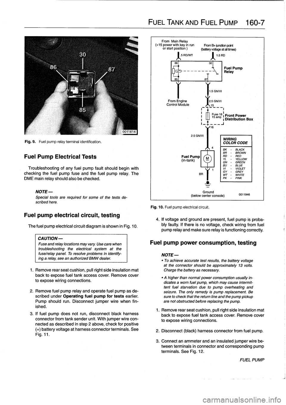
The
fuel
pump
electrical
circuit
diagram
is
shown
in
Fig
.
10
.
3
.
If
fuel
pump
does
not
run,
disconnect
black
harness
connector
from
tank
sender
unit
.
With
jumper
wire
con-
nectedas
described
in
step
2
above,
check
for
positive
(+)
batteryvoltage
at
harness
connector
terminals
.
See
Fig
.
11
.
FUEL
TANK
AND
FUEL
PUMP
160-
7
From
Main
Relay
(+15
power
with
key
in
run
From
B+juretion
point
orstartposition)
(batteryvoRageatalltirnes)
'
.5
RD/Nrr
1
.5
RD
1
.5
GNNI
From
Engine
2
.5
GNNI
Control
Module
15
2
.5
GNNI
Ground
(below
center
console)
Fig
.
10
.
Fuel
pump
electrical
circuit
.
30
-~
Relay
Fuel
Pump
8~T
I
1
s
ám
61
Front
Power
I
a
1
Distribution
Box
I_
16
WIRING
COLOR
CODE
BK
-
BLACK
BR
-
BROWN
Fuel
Pump
RD
-
RED
(in-tank)
M
YL
YELLOWGN
-
GREENBU
-
BLUE
1
VI
-
VIOLET
GY
-
GREY
WT
-
WHITE
PK
-
PINK
0011946
4
.
If
voltage
and
groundare
present,
fuel
pump
is
proba-
bly
faulty
.
If
there
is
no
voltage,
check
wiring
From
fuel
pump
Reay
and
make
sure
Reay
is
functioning
correctly
.
CAUTION-
Fuseandrelaylocationsmayvary
.
Usecara
when
Fuel
pump
power
consumption,
testing
troubleshooting
the
electrical
system
at
the
fuselrelay
panel
.
To
resolve
problems
in
identify-
NOTE-
ing
a
relay,
see
en
authorízed
BMW
dealer
.
"
To
achieveaccurate
testresults,
fhe
battery
voltage
at
the
connector
should
be
approximately
13
volts
.
1.
Remove
rearseat
cushion,
pull
right
side
insulation
mat
Charge
the
battery
asnecessary
.
back
to
expose
fuel
tank
accesscover
.
Remove
cover
.
q
higher
than
normal
power
consumption
usually
fin-
to
expose
wiring
connections
.
dicates
a
worn
fuel
pump,
which
may
cause
intermit-
tentfuel
starvation
due
lo
pump
overheating
and
2
.
Remove
fuel
pump
relay
and
opérate
fuel
pump
as
de-
seizure
.
The
only
remedy
is
pump
replacement
.
Be
scribed
under
Operating
fuel
pump
for
tests
earlier
.
sure
to
check
that
thereturn
fine
and
the
pump
pickup
Pump
should
run
.
Disconnect
jumper
wire
when
fin-
are
not
obstructed
before
replacing
the
pump
.
ished
.
1
.
Remove
rear
seat
cushion,
pull
right
side
insulation
mal
back
to
expose
fuel
tank
accesscover
.
Remove
cover
to
expose
wiring
connections
.
2
.
Disconnect
(black)
harness
connector
from
fuel
pump
.
3
.
Connect
an
ammeter
and
an
insulated
jumper
wire
be-
tween
terminals
in
connector
and
corresponding
pump
terminals
.
See
Fig
.
12
.
FUEL
PUMP
Page 199 of 759
NOTE-
Some
cars
covered
by
this
manual
may
have
an
alter-
nate
cooling
fan
switchwith
switching
temperatures
of
176%190W
(80%88°C)
.
When
replacing
the
switch
check
theswitching
specifications,
whichshouldbe
stamped
on
the
switch
body
.
1
.
If
coolant
is
circulating
at
normal
operating
tempera-
ture,
but
auxiliary
cooling
fan
does
not
run,
disconnect
connector
from
radiator
temperature
switch
and
make
tests
listed
in
Table
c
.
Table
c
.
Auxiliary
Cooling
Fan
Temperature
Switch
Tests
Wires
jumpered
Test
Test
resuits
conditions
Black/green
(terminal2)
and
Ignition
ON
Fan
runs
on
brown
(terminal
1)
low
speed
Black/gray
(terminal
3)
and
Ignition
ON
Fan
runson
brown
(terminal
I
1)
high
speed
2
.
If
fan
runs
only
when
powered
directly
by
jumpered
connector
and
hot
coolant
is
circulating
through
radia-
tor,
radiator
temperature
switch
is
most
likelyfaulty
.
Use
a
new
sealing
ring
when
replacing
switch
Tightening
Torque
"
Temperature
switch
to
radiator
......
15
Nm
(11
ft-Ib)
3
.
If
auxiliary
fan
does
notrun
when
powered
directly,
check
for
battery
voltage
at
temperature
switch
connec-
tor
(black/green
wire)
with
ignition
on
.
If
battery
voltage
is
not
present,
check
fuses
.
See
610
Electrical
Com-
ponent
Locations
.
RADIATOR
AND
COOLING
SYSTEM
170-
5
~r~nmm
a
00
0
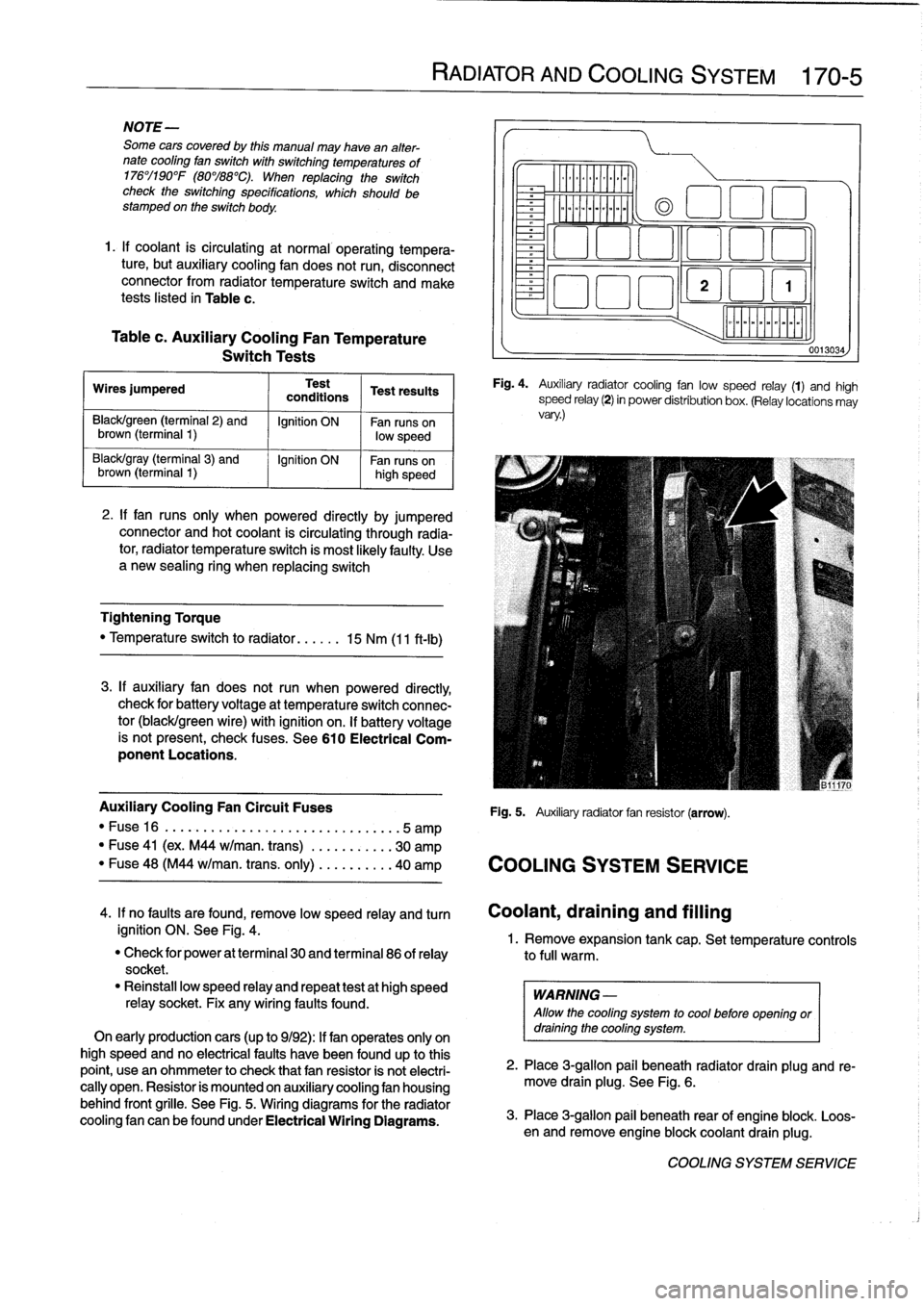
Fig
.
4
.
Auxiliary
radiator
cooling
fan
low
speed
relay
(1)
and
high
speed
relay
(2)
in
power
distribution
box
.
(Relay
locations
may
vary
.)
Auxiliary
Cooling
Fan
Circuit
Fuses
Fig
.
5
.
Auxiliary
radiator
fan
resistor
(arrow)
.
"
Fuse16
.
...................
..
..
...
...
.5
amp
"
Fuse
41
(ex
.
M44
w/man
.
trans)
.
..
.
..
.....
30
amp
"
Fuse
48
(M44
w/man
.
trans
.
only)
..
.
..
.....
40
amp
COOLING
SYSTEM
SERVICE
0013034
4
.
If
no
faults
are
found,
remove
low
speed
relay
and
turn
Coolant,draining
and
filling
ignition
ON
.
See
Fig
.
4
.
1
.
Remove
expansion
tank
cap
.
Set
temperature
controls
"
Check
for
power
at
terminal
30
and
terminal
86
of
relay
to
full
warm
.
socket
.
"
Reinstall
low
speed
relay
and
repeat
testat
high
speed
WARNING
-
relay
socket
.
Fix
any
wiring
faults
found
.
Allow
the
cooling
system
to
cool
before
openlng
or
On
early
productioncars
(up
to
9/92)
:
If
fan
operates
only
on
draining
the
cooling
system
.
high
speed
and
no
electrical
faults
have
been
foundup
to
this
point,
usean
ohmmeter
to
check
that
fan
resistor
is
not
electri-
2
.
Place
3
ra
allo
ug
.
beneath
radiator
drain
plug
and
re-
cally
open
.
Resistor
is
mounted
on
auxiliary
cooling
fan
housing
move
drain
plg
.
See
Fig
.
6
.
behind
front
grille
.
See
Fig
.
5
.
Wiring
diagrams
for
the
radiator
cooling
fan
canbefoundunder
Electrical
Wiring
Diagrams
.
3
.
Place
3-g
pail
beneath
rear
of
engine
blo
.
Loos-
en
and
re
mlon
ove
engine
blockcoolant
drain
plug
k
.
COOLING
SYSTEM
SERVICE
Page 387 of 759
610
Electrical
Component
Locations
GENERAL
...........
.
.
.
.
.
.
.
.
.
........
610-1
FOSE
POSITION
TABLES
..
.
.
.
.
.
.....
.
610-19
FUSE
AND
RELAY
POSITIONS
.
...
.
.
.
.
.
610-1
Fuse
Positions
.
.
.
................
.
.
.
.
.
610-1
Relay
Positions
.
.
.
.....
.
.
.
........
.
.
.
.
.
610-2
Auxiliary
RelayPanel
.....
.
...
.
........
.
610-2
SplicePanel,
Left
.
.
.
...
.
.
.
...
.
........
.
610-2
SplicePanel,
Right
.
.
.
.
.
.
.
.
...
.
.........
610-3
COMPONENT
LOCATIONS
.
.
.
.
.......
.
.610-3
Component
Location
Table
.
.
.
.
.
.
.........
610-9
GENERAL
FUSE
AND
RELAY
POSITIONS
This
repair
group
covers
f
use,
relay,
and
control
module
lo-
The
front
power
distribution
box,
an
auxiliary
relay
panel,cation
information
.
Electrical
equipment
and
accessories
in-
and
two
auxiliary
splice
panels
contain
most
of
the
fuses
and
stalled
varies
depending
on
model
and
model
year
.
Always
relays
in
E36
vehicles
.
Refer
to
the
component
location
later
confirm
that
the
proper
electrical
component
has
been
identi-
in
this
section,
as
well
as
the
tables
at
the
end
of
this
repair
fied
by
using
the
electrical
wiring
diagrams
.
group
for
electrical
component
location
.
WARNING
-
On
cars
equipped
with
airbags,
special
precautionsapply
to
any
electrical
system
testing
orrepair
.
Air-
bag
units
areexplosive
devices
and
mustbe
han-
dled
with
extremecare
.
Before
starting
any
work
onan
airbag
equipped
car,
refer
to
the
wamings
and
cautions
in
721
Airbag
System
(SRS)
.
CAUTION
-
"
Prior
to
disconnectiog
the
battery,
read
the
bat-
tery
disconnection
cautions
given
at
the
front
of
this
manual
on
page
viii
.
"
Relay
and
fuse
positions
are
subject
to
changeand
may
varyfrom
car
to
car
.
If
questions
arise,
an
authorized
BMW
dealer
is
the
best
source
for
the
most
accurate
and
up-to-date
information
.
"
A
good
way
to
verify
a
relay
position
isto
com-
pare
the
wiring
colors
at
the
relay
socket
to
thecolors
indicated
on
the
wiring
diagrams
located
at
the
rear
of
this
manual
.
"
Always
switchthe
ignition
off
and
disconnect
the
negative
(-)
battery
cable
before
removing
any
electrical
components
.
"
Connect
and
disconnect
ignition
system
wires,
multiple
connectors,
and
ignition
test
equipment
leads
only
while
the
ignition
is
switched
off
.
"
Only
usea
digital
multimeter
for
electrical
tests
.
ELECTRICAL
COMPONENT
LOCATIONS
610-1
TABLES
a
.
E36Component
Locations
...........
.
.
..
...
610-10b
.
1992
E36
Fuse
Positions
..........
..
.
.
.....
610-20c
.
1993
E36
Fuse
Positions
..........
..
..
.
....
610-22d
.
1994
E36
Fuse
Positions
.........
...
.......
610-24e
.
1995
E36
Fuse
Positions
.........
...
.......
610-26
f
.
1996
E36
Fuse
Positions
.........
...
.......
610-28g
.
1997-1998
E36
Fuse
Positions
..
.
..
...
.......
610-30
Fuse
Positions
CAUTION
-
"
Replace
fuses
with
those
of
the
same
rating
.
In-
stalling
a
fuse
with
higher
rating
can
lead
to
cir-
cuit
failure
and
may
also
start
a
fire
.
"
Relay/fuse
positions
vary
by
model
and
equip-
ment
.
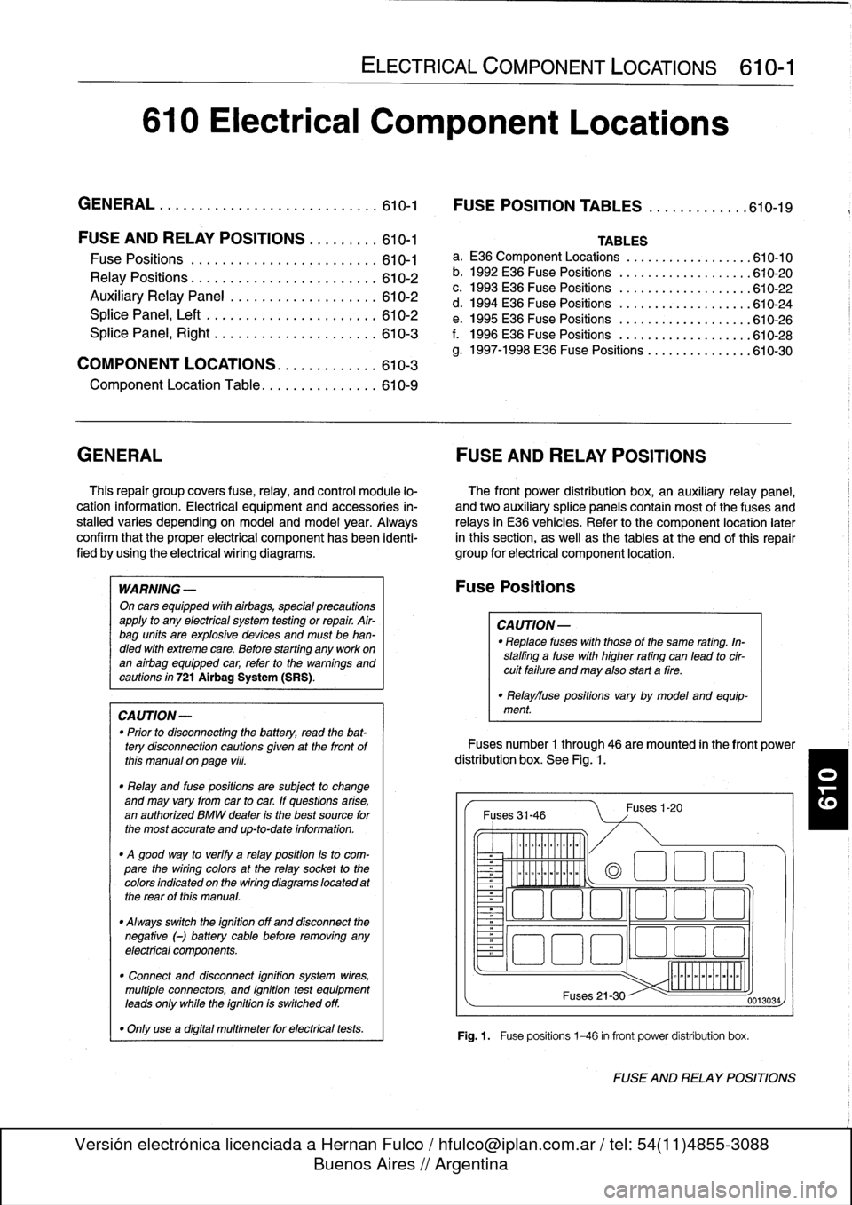
Fuses
number
1
through
46
are
mounted
in
the
front
power
distribution
box
.
See
Fig
.
1.
Fuses
31-46
~
Illlllllllll
°
-
Ilmmlmomlmoi
Fuses
1-20
(a
1
:1
E
El
~
~O!7
L~~n
4~
i
Fuses
21-30
Fig
.1.
Fuse
positions
1-46
in
front
power
distribution
box
.
0013034
FUSE
AND
RELAY
POSITIONS
Page 486 of 759
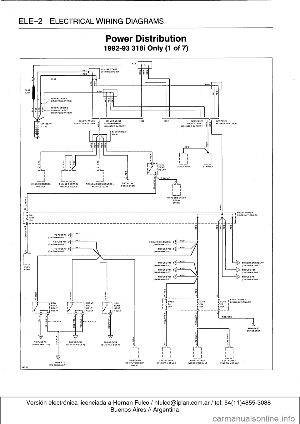
ELE--2
ELECTRICAL
WIRING
DIAGRAMS
FUSE
LINK
64766
I-i
I
-
i
a
1
I
_
ZJ
I
I
I
I
I
I.
4
2
GRN/VIO
I_I
!
___I
I_I
1
D>
6
END
INECONTROL
ENGINECONTROL
TRANSMISSION
CONTROL
DATALINK
MODULE
MODULE
RELAY
MODULE
(EGS)
CONNECTOR
I
I
I
I
5
(F18
--_______________________________________________
O19~
N
RIBUON
BOX
I
FUSE
II
15A
o~___________________________________________________Q~____-aft
TO
FUSE
F5
C
RED
(DIAGRAM
6
OF
7)
FUELPUMP
I
(DIAGRAM60F7)
C'
RED
\
L------r>
(DIAGRAM60F7)
I
LOW
F
I
FRONT
HIGH
BEAM
FOGJ
BEAM
I
I
LIGHT
I
I
LIGHT
I
j
/
I
LIGHT
RELAY
I
RELAY
li
SJ
RELAY
1992
1993W/TRUNK
MOUNTEDBATTERV
1993W/ENGINE
COMPARTMENTMOUNTEDBATTERV
1993W/TRUNK
1993W/ENGINE
1992
1992
WI
ENGINE
W/TRUNK
BATTERY
MOUNTEDBATTERV
¢)
MOUNTED
BATTERY
MOUN
O
TEDBATT
I
ERV
¢I¢I
MOUNTEDBATTERV
TOFUSEF40
<
,.k
RED
(DIAGRAM
6
OF
7)
I
I
(DIAGRAM
3
OF
7)
TO
FUSEF3
E
RED
(DIAGRAMfiOF7)
"
.
1k
I
(DIAGRAM
6OF7)
>I
mJ~CANADA
RED
BNUMPSTART
JUNCTION
POINT
REO
Power
Distribution
1992-93
318i
Only
(1
of
7)
-UNCTION
POINT
TOFUSEF15
TO
FUSE
F29
(DIAGRAM60F7)
(OIAGRAM6OF7)
I
~1
.
FUEL
_I
I
_I
~
(PUMP
GENERATOR
STARTER
I
,(
I
RELAY
TO
IGNITION
SWITCH
QA
TOFUSE
F20
TOFUSEF19
FRED
(DIAGRAM6OF7)
`
I
III
-
(DIAGRAM70F7)
OXVGENSENSOR
RELAY
(4CVL)
RED
RED
RED
ON-BOARD
LEFTPOWERRIGHTPOWERLEFTPOWER
TOFUSEF17
COMPUTERHORN
WINDOWMODULE
WINDOWMODULE
WINDOW
MODULE
(DIAGRAM
60F
7)
RELAY
TO
COMFORTRELAV
Page 487 of 759
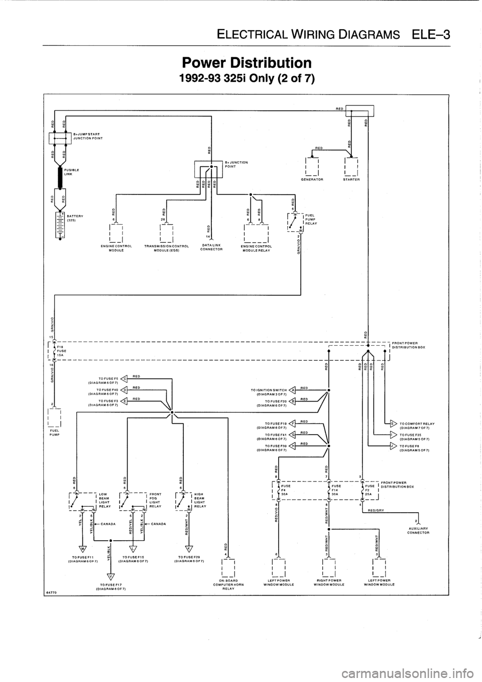
ELE
Power
L
1992-9332
RED
E01
IIIII
FUSIBLE
LINK
I
GENERATOR
STARTER
BATTERY
¢
(FUEL
-
(325)
S
26
66
PUMP
I
I
RELAY
2
G
ENGINE
CONTROL
TRANSMISSION
CONTROL
DATA
LINK
ENGINECONTROL
iMODULE
MODULE
(EGG)
CONNECTOR
MODULE
RELAY
15
--
---
-
-
----
--
FRONT
POWER
FUSE
r
-
i
DISTRIBUTIONBO
;
I
16A
R
ITIT
TO
FUSE
FS
ED
C
(DIAL
RAM
6
OF
7)
TO
FUSE
F40
D
RED
TO
IGNITION
SWITCH
A
RED
(DIAGRAM
6
OF
7)
(DIAGRAM
3
OF
7)
TO
FUSE
F3
E
RED
TO
FUSE
F20
B
RED
2
(DIAGRAM6OF7)
(DIAGRAM
6OF7)
I
I
I
I
-
I
TOFUSEF19
:
:!!RED---
RED
S
TOCOMFORTI
(DIAGRAM
6
OF
7)
(DIAGRAM
70
FUEL
PUMP
TO
FUSE
F41
V\
TOFUGEF35
(DIAGRAM
B
OF
7)
\
(DIAGRAM
50
TOFUSEFSB
H
RED
"
J
TOFUSEF
.
(DIAGRAM
6
0F
7)
(DIAGRAM
50
8
7
3
FUGE
FUSE
FUSE
I
FRONT
POWER
B
6
6
DISTRIBUTION
BOX
F4
F14
F2
I
LOW
FRONT
HIGH
I
30A
30A
~
.1
.
25A
BEAM
F
I
FOG
F
(
BEAM
i
_________
_____
J
I
I
LIGHT
I
I
LIGHT
I
.
I
LIGHT
l
RELAY
I
-
RELAY
I
-
WJ
_RELAY
6
B
4
-
-
-
O
RED/GRY
3
21
2
B
62
2
~
-
CANADA
j
m
-CANADA
3
"
AUXILIAI
CONNECT
"
3
3
M
L
K
4(D
IAGAGR
AM60
F7)
(DIAGRAM
IAGRAM
B
OFOF
7)
(DIAGRAM
6
0
6
3
3G
FO
F
~
7)
I
I
I
I
I
II
I
I
I
I
I
I
I
!
_I
!
_I
!
_I
!
_
17
I
ON-BOARD
LEFTPOWER
RIGHTPOWER
LEFT
POWERTOFUSEFI7
COMPUTERHORN
WINDOW
MODULE
WINDOWMODULE
WI
NDOWMODULE
(DIAGRAMS
OF7)
RELAY
64770
Page 488 of 759
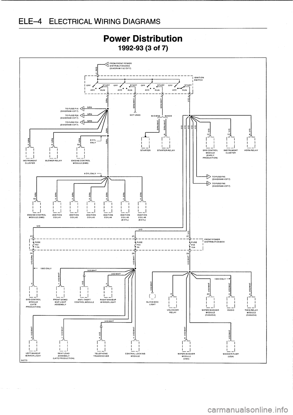
CAL
WIRING
DIAGF
Power
Di
;
1992-93
~~~A
"'0""0"'0"',
///
°°°
DISTRIBUTION
BOX
o/
(DIAGRAM1820F7)
5-
-
-
-
-
-
-
-
-
-
-
-
-
-
-
--
-
-
-
---
-
-
-
I
IGV
NITfON
3
TOFUSEF16
NGRN
.
(DIAGRAM
4
OF
7)
TOP
.SEF28
0GRN
NOTUSED
W/OEGS
W`EGS
(CIA
40F7)
TOFU
SEF24
P
GRN
(DIAGRAM40F7)
33
>>>>>
O>
>
>
?
"
8
12
15
B
a
a
6CYL
-
f
I
I
I
I
I
I
I
I
I
I
ONLY
I
I
I
I
I
I
I
I
I
I
-
I-_I
I
I
I
I
I
STARTER
STAR
-
TER
RELAY
SRSCONTROL
INSTRUMENT
HORN
RELAY
I
I
I
I
I
J
MODULE
CLUSTER
L-I
I
_
I
I
(EARLY
PRODUCTION)
INSTRUMENT
BLOWER
RELAY
ENGINE
CONTROL
CLUSTER
GDULE
(DME)
4
CYL
ONLY
T
TO
FUSEF45
(DIAGRAM
4
OF
7)
-
U
TO
FUSEF46
(DIAGRAM
40F7)
t7
t7
t7
5fi
3
3
3
3
3
3
I
I
I
II
I
I
I
I
I
I
I
I
I
I
I
I
I
I
I
I
I
I
I
I
I
I
I
ENGINECONTROL
IGNITIONIGNITIONIGNITION
IGNITION
IGNITIONIGNITION
MOOULE(DME)
CO-1
CO
ILk2
CO
ILp3
CO
L
.1
COILkS
CO
L#6
HI
CYL)
IS
CYL)
VIO
23
VIO
26
27
FRONTPOWER
.
I
SE
FUSE
FUSE
I
DISTRIBUTIONBO%
FU
J5______________-_
.-
.__________
A________________16
24
26
2i
3
'
o
1993
ONLY
VIO/W
HT
VIO/WHT
0
1993ONLY
~
0
3
3
3
I
I
I
I
I
I
I
I
;
'
I
I
I
I
I
I
I
I
_
23
>t
5
4
SRSCONTROL
FRONTDOME/
ANTI-THEFT
RIG
!
HT
MAKE
UP
I
I
I
I
I
I
I
I
MODULE
MAP
LIGHT
Co
NTROLMODULE
MIRRORLIGHT
GLOVEBOX
I
I
I
I
I
I
I
I
(LATE
ASSEMBLY
LIGHT
I
-
I
I
-
I
I
-
I
I
-
I
PRODUCTION)
UNLOADER
WIPER/WASHER
RADIO
TWIN
RELAYRELAY
MODULE
MODULE
(CANADA)
(CANADA)
VIO/WHT
0
0
3
3>
>
>
33
1
5
7
B
I
I
I
I
I
I
I
I
I
I
I
I
I
I
I
I
I
I
I
I
I
I
I
I
LEFTMAKEUP
SEATLOAD
TELEPHONE
CENTRALLOCKING
WIPE
/WASHER
WASHERPUMP
MIRROR
LIGHT
ASSEMBLY
TRANSCEIVER
MODULE
MODULE
(USA)
(LATE
PRODUCTION)
64773(USA)
Page 489 of 759
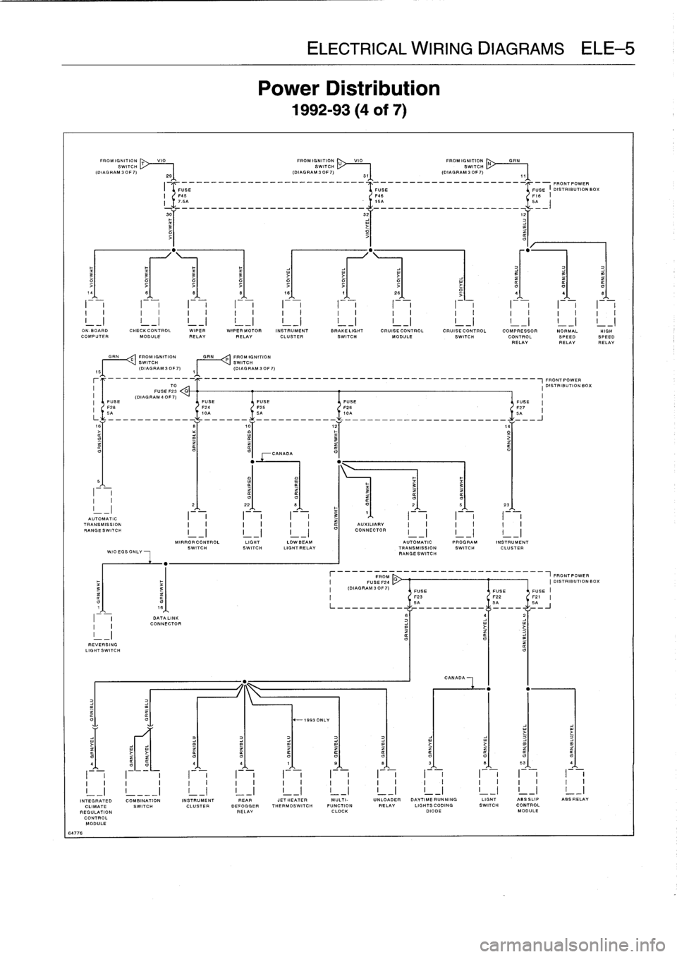
EKE
Power
1992-
VIO
FROMIGNITION
U
VIO
FROM
IGNITI
ON
SWITCH
SWITCH
2S
(DIAGRAM3OF7)
31
(DIAGRAM3OF7)
I
-
______________-__________--
4
-_____________________I_-FRONT
POWER
O
3
3
3
3
i
14
8
8
B
18
7
26
-
4
4
I
i
I
I
i
-F-
I
i
I
-
,
I
,
I
I
F-,
ON
-BOARD
CHECKCONTROL
WIPER
WIPER
MOTOR
INSTRUMENT
BRAKELIGHT
CRUISE
CONTROL
CRUISE
CONTROL
COMPRESSOR
NORMALCOMPUTER
MODULE
RELAYRELAY
CLUSTER
SWITCH
MODULE
SWITCH
CONTROL
SPEEDRELAYRELAY
GRN
0
FROM
IGNITION
GRN
P
FROM
IGNITION
~I
I
VSWITCH
SWITCH
(DIAGRAM
30F7)
,~
(DIAGRAM
3OF7)
-------_-_____________________________________________~FRONT
POWER
TO
I
DISTRIBUTIONBOX
FUSE
F23
G
(DIAG
RAM
4
0F
7)
I
FUSE
FUSE
FUSE
FUSE
FUSE
'
F26
F24
F25
F26
-
F27
6A
10A
SA
ICA
5A
is
S
,0
12
,4
o3
>
CANADA
5
I
~
~
~
3
33
-
2
22
B
F
O
2
5
23
AUTOMATIC
I
I
I
3
1
I
TRANSMISSION
AUXILIARY
RANGESWITCH
I
-
I
I
-
I
I
-
I
CONNECTOR
MIRRORCONTROL
LIGHT
LOWBEAM
AUTOMATIC
PROGRAM
INSTRUMENT
SWITCHSWITCH
LIGHTRELAY
TRANSMISSION
SWITCH
CLUSTER
WIOEGSONLY
RANGESWITCH
FROM
___________-----1FRONTPOWER
FUSEF24
CI
DISTRIBUTION
BC
3
(DIAGRAM30F7)
FUSE
FUSEFUSE
F23
F22
F21
O
O
SA
SA
5A
DATA
LINK
6
j
2
I
CONNECTOR
REVERSING
LIGHTSWITCH
CANADA
O
"
-1993
ONLY
O4
4
4
1
S
B
3
B
53
4
I
v
I~
i
I
i
I
v
I
i
I
v
I
i
I
v
I
i
I
i
I
i
v
v
v
v
~
v
v
~
~
v
v
~
v
v
o
n
v
v
v
v
v
v
_I
INTEGRATED
COMBINATION
INSTRUMENT
REAR
JETHEATER
MULTI-
UNLOADER
DAYTIMERUNNING
LIGHT
ASSSLIP
ABSRELAY
CLIMATE
SWITCH
CLUSTER
DEFOGGER
THERMOSWITCH
FUNCTION
RELAY
LIGHTSCODING
SWITCH
CONTROL
REGULATION
RELAY
CLOCK
DIODE
MODULE
CONTROL
MODULE
64776
Page 490 of 759
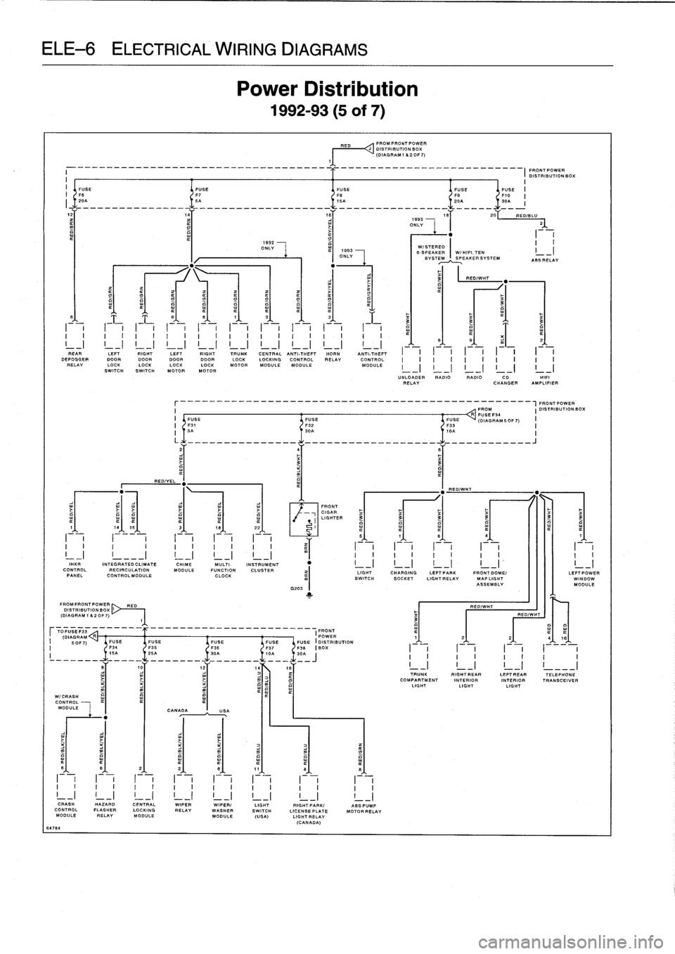
CALWIRING
DIAGF
Power
Di
:
1992-93
RED
FROMFRONTPOWER
DISTRIBUTION
BOX
(DIAGRAM
1
620F7)
1
FRONTPOWER
DISTRIBUTION
BOX
i
I
I
1592
II
ONLY
WI
STEREO
-
I
ONLY
6-
SVS
SPEAKER
I
W/HIFI,TEN
I
TE~~PEAKERSYSTEM
ASSRELAY
3
RED/WHT
O
t7
0
t7
3
6
6
8
1
3
¢
3
F
~
~
3
a
a
o
I
I
I
II
I
I
I
I
I
I
I
I
I
I
I
I
I
i
I
¢
5
s
z
I
REAR
I
I
LEFT
I
I
RIGHT
I
I
LEFT
I
I
RIGHT
I
I
TRUNK
I
CENT
RA
I
L
ANTI-THEFT
I
HORN
I
ANTI-THEFT
I
I
I
I
I
I
I
I
I
I
DEFOGGERDOOR
DOOR
DOORDOOR
LOCK
LOCKING
CONTROL
RELAY
CONTROL
II
I
IIIIIII
RELAY
LOCK
LOCKLOCKLOCK
MOTOR
MODULEMODULE
MODULE
I
_
II
-
II
_
II
-
II
_
I
SWITCHSWITCH
MOTORMOTOR
UNLOADER
RADIO
RADIO
CD
HIF'
RELAY
CHANGER
AMPLIFIER
r________________________________________________-FRONT
POWER
I
FROM
I
DISTRIBUTION
BOXR
FUSE
I
FUSE
FUSE
FUSE
(DIAGRAMSOF7)
I
F31
F32
F33
II
5A
30A
I,0
OA
I
L
-----
______
.......
.
.
.
.
.
.
.
.
.
..
________J
z
4
6
3
3
a
"
"
REDIYEL
RED/WHT
"
FRONT
Y
CIGAR
I
LIGHTED
3
3
3
3
3
3
1
-
19
15
3
-
18
-
22
-
I
_
_I
I
I
iI
(
I
II
5
1
s
s
1
I
I
I
I
II
I
I
II
~
(-
I
I
I
I
-
I
II
IiI
_I
!
___I
!
_I
!
_I
i
-I_
I
I
I
I
I
I
I
I
I
I
I"
KIM
INTEGRATED
CLIMATE
CHIME
MULTI-
INSTRUMENT
"
I
_I
I
-
I
I
~I
I
-I
I
_I
CONTROL
RECIRCULATION
MODULE
FUNCTION
CLUSTER
LIGHT
CHARGING
LEFTPAPK
FRONT
DOME/
LEFT
POW
PANEL
CONTROLMODULE
CLOCK
SWITCH
SOCKET
LIGHTRELAV
MAP
LIGHT
WINDON
ASSEMBLY
MODULE
G203
1
FROMFRONTPOWER
RED
RED/WHT
DISTRIBUTION
BOX
(DIAGRAM
1
82OF7)
RED/WIT
3
TFUSEF33
FRONT
ODAORAM
R
______
__________________-
I
POWER
¢
1
2
2
416
I
SOFT)
FUSE
FUSE
FUSE
FUSE
FUSEFUSE
(DISTRIBUTION
F34
136
F37
F38
BOX
I
I
II
III
I
z'235
A-____
t0A
-
30=~
IIIII11I
10
1z
14Es
TRUNK
RIGHTREAR
LEFTREAR
TELEPHONE
COMPARTMENT
INTERIOR
INTERIOR
TRANSCEIVER
LIGHT
LIGHTLIGHT
P
W1
C
RASH
CONTROL
MODULE
CANADAUSA
fl
6
2
2
8
11
8
0
I
I
I
I
I
I
I
I
I
I
I
I
I
I
I
II
I
I
I
I
I
I
I
I
I
I
I
I
I
I
I
CRASH
HAZARD
CENTRAL
WIPER
WIPER/
LIGHT
RIGHTPARK/
ABSPUMP
CONTROLFLASHER
LOCKING
RELAY
WASHER
SWITCH
LICENSEPLATE
MOTORRELAV
MODULE
RELAY
MODULE
MODULE
(USA)
LIGHTRELAV
(CANADA)
64784