automatic BMW M3 1998 E36 Repair Manual
[x] Cancel search | Manufacturer: BMW, Model Year: 1998, Model line: M3, Model: BMW M3 1998 E36Pages: 759
Page 240 of 759
250-
6
GEARSHIFT
LINKAGE
Shift
interlock,
checking
function
1
.
Shift
selectorlever
to
park
(P)
position
and
turn
ignition
(automatic
transmission)
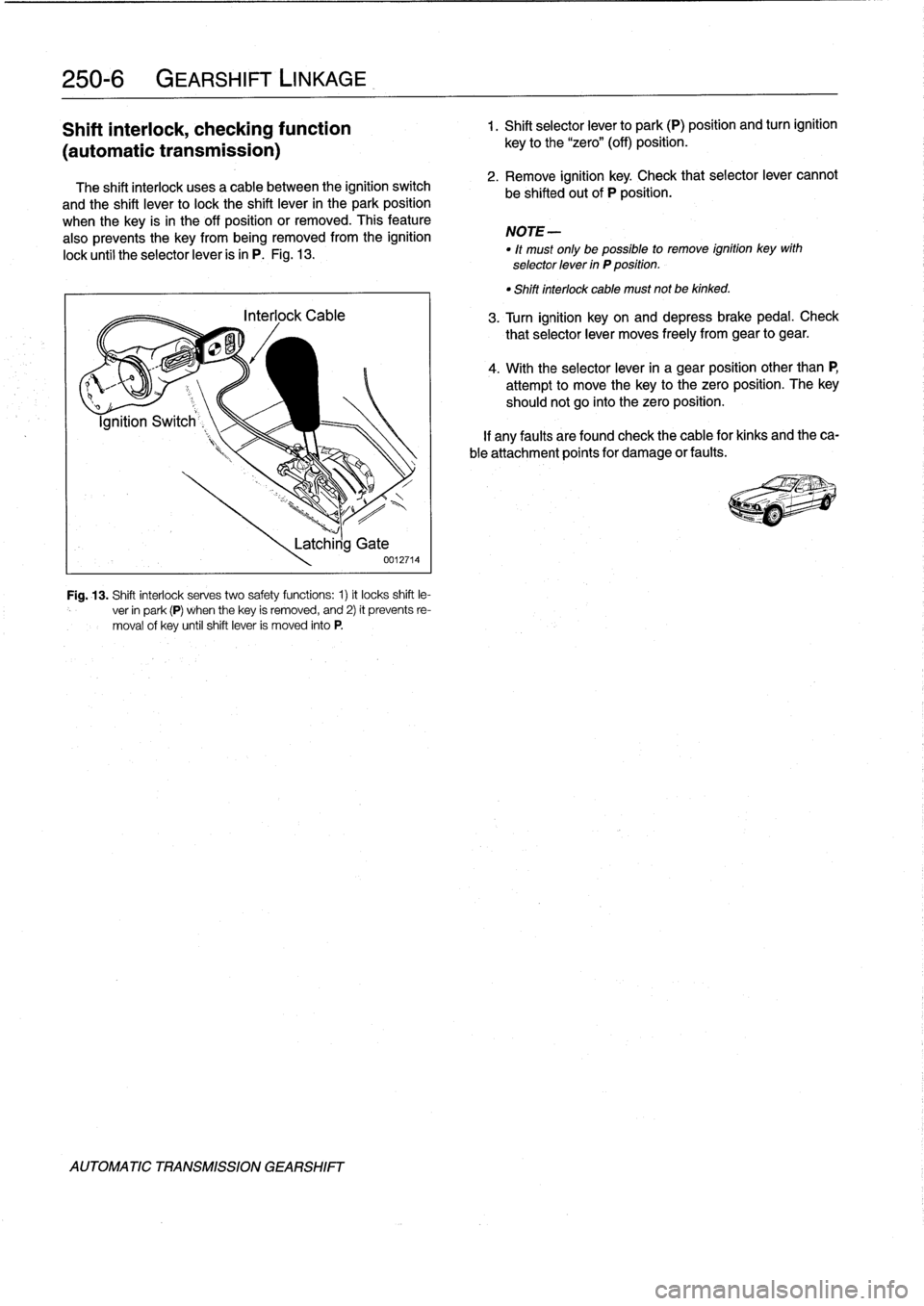
The
shift
interlock
usesa
cable
between
the
ignition
switch
and
the
shift
lever
to
lock
the
shift
lever
in
the
park
position
when
the
key
is
in
the
off
position
or
removed
.
This
feature
also
prevents
the
key
from
being
removed
from
the
ignition
lock
until
the
selectorlever
is
in
P
.
Fig
.
13
.
Fig
.
13
.
Shift
interlock
serves
two
safety
functions
:
1)
it
locks
shift
le-
ver
in
park
(P)
when
thekey
is
removed,
and
2)
it
prevents
re-
moval
of
key
untilshift
lever
is
moved
into
P
.
AUTOMATIC
TRANSMISSION
GEARSHIFT
Latchirig
Gate
0012714
key
to
the
"zero"
(off)
position
.
2
.
Remove
ignition
key
.
Check
that
selectorlever
cannot
be
shifted
out
of
P
position
.
NOTE-
"
lt
must
only
be
possible
to
remove
ignition
key
with
selector
lever
in
P
position
.
"
Shiftinterlock
cable
must
not
be
kinked
.
3
.
Turn
ignition
keyon
and
depressbrakepedal
.
Check
that
selectorlever
moves
freely
from
gear
to
gear
.
4
.
With
the
selectorlever
in
a
gear
position
other
than
P,
attempt
to
move
thekey
to
the
zero
position
.
The
key
shouldnot
go
into
the
zero
position
.
If
any
faults
arefound
check
the
cable
for
kinks
and
theca-
ble
attachment
points
for
damage
or
faults
.
Page 251 of 759
Wheel
brake
caliper
Electronic
control
module
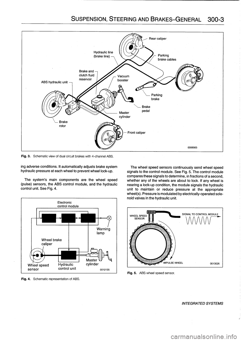
Fig
.
4
.
Schematic
representation
of
ABS
.
SUSPENSION,
STEERING
ANDBRAKES-GENERAL
300-3
Fig
.
3
.
Schematic
view
ofdual
circuit
brakes
with
4-channel
ABS
.
ing
adverse
conditions
.
It
automatically
adjusts
brake
system
hydraulic
pressure
at
each
wheel
to
prevent
wheel
lock-up
.
The
system's
main
components
arethe
wheel
speed
(pulse)
sensors,
the
ABS
control
module,
and
the
hydraulic
control
unit
.
See
Fig
.
4
.
Warning
lamp
u
Master
Whee
_
l
speed
I-lydraulic
cylinder
sensor
control
unit
0012135
UNI
The
wheel
speed
sensors
continuously
send
wheel
speed
signals
to
the
control
module
.
See
Fig
.
5
.
The
control
module
compares
these
signals
to
determine,
in
fractions
of
a
second,
whether
any
of
the
wheels
areabout
to
lock
.
If
any
wheel
is
nearing
a
lock-up
condition,
the
module
signals
the
hydraulic
unit
to
maintain
or
reduce
pressure
at
the
appropriatewheel(s)
.
Pressure
is
modulated
by
electrically-operated
sole-
noid
valves
in
the
hydraulic
unit
.
Fig
.
5
.
ABS
wheelspeed
sensor
.
0006563
INTEGRATED
SYSTEMS
Page 253 of 759
NOTE-
The
traction
control
system
referred
to
as
AST
(all
sea-
son
traction)
may
also
be
referred
to
as
ASC
(Automat-
ic
Stability
Control)
and
ASC+T
(Automatic
Stability
Control+Traction)
.
The
AST
system
improves
traction
by
electronically
apply-
ing
the
rear
brakes
when
therear
drive
wheels
are
spinning
at
a
faster
rate
than
the
front
wheels
.
The
combined
ABS/AST
control
module,
operating
through
the
ABS
hydraulic
control
unit,
modulates
braking
force
at
therear
wheels
.
In
addition,
AST
uses
retarded
ignition
timing
and
an
auxil-iary
engine
throttle
plate
to
reduceengine
torque
and
maintain
vehicle
stability
.
The
auxiliary
throttle
plate
is
held
open
by
spring
pressure
.
The
AST
system
actívates
the
auxiliary
throttie
position
motor
(ADS)
to
cose
the
AST
throttle
as
needed
.
This
reduces
the
volume
of
engine
intake
air
.
Due
to
the
throttle
closing
very
rapidly
during
AST
operationthe
driver
cannot
increase
theengine
power
output
regardless
of
how
far
theaccelerator
pedal
is
pushed
to
the
floor
.
The
auxiliary
throttle
plate
is
placed
ahead
of
the
conven-
tional
throttle
plate
in
the
throttle
body
.
Traction
control
also
comes
into
operationduringdecelera-
tion
.
Decelerating
on
snowy
or
icy
road
surfaces
can
lead
to
rear
wheel
slip
.
If
a
rear
wheel
startsto
drag
or
lock
up
when
the
throttle
is
closed
rapidly
orduringdownshifting,the
AST
system
can
limit
the
problem
by
advancing
the
ignition
timing
.
A
switch
on
the
center
console
is
used
to
togglethe
AST
on
or
off
.
The
AST
system
is
designed
to
be
maintenance
free
.
There
are
no
adjustments
that
can
be
made
.
Repair
and
trouble-
shooting
of
the
AST
system
requires
special
test
equipment
andknowledgeand
should
be
performed
only
by
an
autho-
rized
BMW
dealer
.
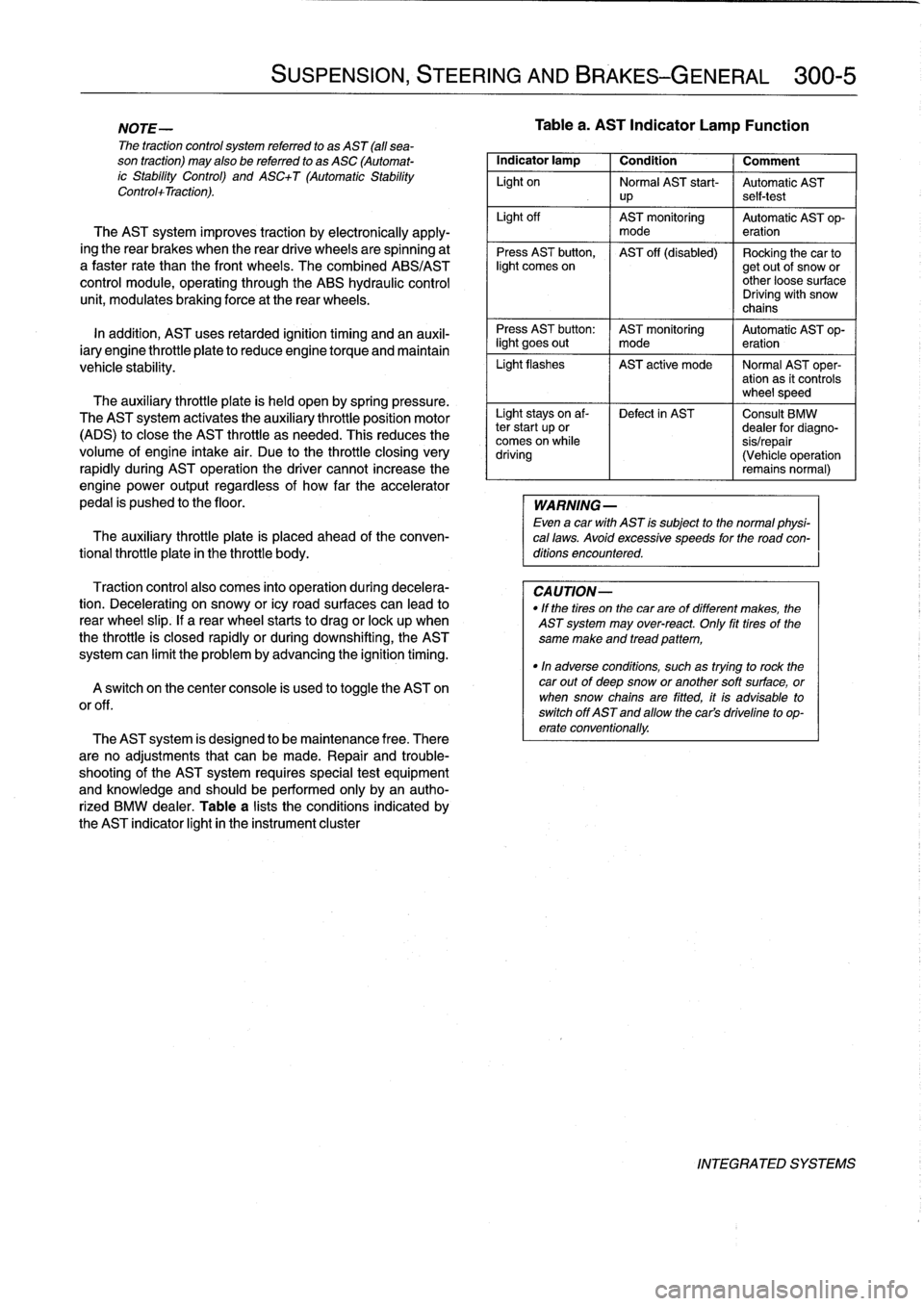
Table
a
lists
theconditions
indicated
by
the
AST
indicator
light
in
the
instrument
cluster
SUSPENSION,
STEERING
AND
BRAKES-GENERAL
300-5
Tablea
.
AST
Indicator
Lamp
Function
Indicator
lamp
1
Condition
1
Comment
Light
on
Normal
AST
start-
Automatic
AST
up
self-test
Light
off
AST
monitoring
Automatic
AST
op-
mode
eration
Press
AST
button,
AST
off
(disabled)
Rocking
the
car
tolight
comes
on
getout
of
snow
or
other
loose
surface
Driving
with
snow
chains
Press
AST
button
:
AST
monitoring
Automatic
AST
op-
light
goes
out
I
mode
eration
Light
flashes
AST
active
mode
I
Normal
AST
oper-
ation
as
it
controls
wheel
speed
Light
stays
on
af-
Defect
in
AST
Consult
BMW
ter
start
up
or
dealer
for
diagno-
comes
on
while
sis/repair
driving
(Vehicle
operation
remains
normal)
WARNING
-
Even
a
car
with
AST
is
subject
to
the
normal
physi-
cal
laws
.
Avoid
excessive
speeds
for
the
road
con-
ditions
encountered
.
CAUTION-
"
If
the
tires
on
the
carare
of
different
makes,
the
AST
system
may
over-react
.
Only
fit
tires
of
the
same
make
and
tread
pattem,
"In
adverse
conditions,
such
as
trying
to
rock
the
car
outof
deep
snow
or
another
soft
surface,
or
when
snow
chainsare
fitted,
it
is
advisable
to
switch
off
AST
and
allow
the
cars
driveline
to
op-
erate
conventionally
.
INTEGRATED
SYSTEMS
Page 305 of 759
TheE36
convertible
is
an
all-season
vehicle
with
a
high
lev-
e¡offunctionality,
excellent
interior
comfort,
and
acoustic
re-
finement
.
Interior
materials
and
colors,
the
soft
top
and
the
light-alloy
wheelshave
been
carefully
matched
.
Various
versions
of
manual
and
automatic
soft
tops
have
been
used,
with
the
fully
automatic
convertible
roof
being
in-
stalled
beginning
in
the
1997
model
year
.
A
hard-top
in
body
color
with
heated
rear
window
is
avail-
ableas
an
option
for
the
cold
season
.
BODY-GENERAL
400-
3
Coupe
Models
The
convertible
body
structure
includes
many
passive
safe-
ty
refinements
over
its
fixed-top
counterparts
.
Some
of
the
en-
TheE36
coupe
is
similar
to
the4-door
sedan,
but
has
a
hancements
include
:
more
stretched
and
sleeker
appearance
.
Thus,
with
the
same
wheelbase
and
identicallength,
it
looks
different
but
still
famil-
"
More
rígíd
underbody
.
iar
.
"
Transverse
seat
members
.
"
Reinforced
windshield
frame
with
bonded
windshield,
The
2-door
variant
differs
from
the
4-door
sedan
by
a
3
.12
and
tubular
door
reinforcements
.
inch
(8
cm)
longer
front
end,
a
flatter
hood
line
with
air
slits,
"
Rollover
protection
system,
which
is
tripped
into
position
and
a
roof
almost
1
.2
inches
(3
cm)
shorter
.
Additional
differ-
in
a
fraction
of
second
.
This
is
available
as
optional
ences
include
wider
doors
with
frameless
Windows,
glass-
equipment
(standard
on
the
1998
328iC)
and
may
be
fit-
covered
door-posts
(B-pillars)
and
a
shorter
and
lower
lug-
ted
to
earlier
convertible
models
.
With
this
feature,
two
gage
compartment
lid
.
bars
fully
independent
of
each
other
come
up
behind
each
rear-seat
backrest
when
the
vehicle
is
in
danger
of
Convertible
Models
turning
over
.
A
convertible
body
normally
flexes
and
vibrates,
transfer-
ring
oscillations
to
the
luggage
compartment
.
In
the
E36
con-
vertible,
BMW
utilizes
a
special
battery
in
the
luggage
compartment,
in
conjunction
with
a
unique
battery
tray,
asa
vibration
dampening
system
to
counteract
thisoscillation
.
CAUTION
-
The
E36
convertible
requires
a
specialbattery
which
is
designed
for
constant
vibration
.
Information
for
the
convertible
top
and
its
related
mecha-
nisms
can
be
found
541
Convertible
Top
.
BODYASSEMBLY
Page 306 of 759
400-
4
BODY-GENERAL
INTERIOR
EQUIPMENT
E36
interiors
have
a
unique
character,
with
a
combínation
of
sporty
features
and
innovative
design
.
Al¡
body
versions
were
made
in
a
wide
choice
of
interior
and
exterior
colors
.
New
colors
with
matching
leather
and/or
fabric
upholstery
were
in-
troduced
for
each
model
year,
including
light-alloy
wheels
in
new
designs
.
Driving
comfort
is
enhanced
by
power
steering,
tilt
steering
wheel
(optional),
height-adjustable
front
seats,
and
electrical-
ly
adjustable
and
heated
rear-view
mirrors
.
Inside
thecar
there
are
reading
lights
at
four
seating
positions
.
Seats
and
Seat
Belts
NOTE-
Theseat
base
usedon
cars
with
pyrotechnic
seatbelt
Anatom¡cal
ly-correct
seats
are
constructed
from
polyure-
tensioners
is
not
interchangeable
with
the
earlier
seat
thane
foam
containing
areas
or
"zones"
of
different
firmness
.
base
.
The
seat
bases
have
steel
springs
for
added
support
and
strength
.
The
power
seats
are
provided
with
conveniently
lo-
Instruments
and
Controls
cated
switches
along
the
outside
edge
of
the
seat
.
Heated
seats
are
an
option
in
all
models
.
See
520
Seats
for
more
de-
Everything
in
the
interior
passenger
compartment
essential
tails
.
to
the
driver
is
logically
grouped
and
easy
to
reach
.
Al¡
instru-
ments
and
controls
havebeen
arranged
ergonomically
and
The
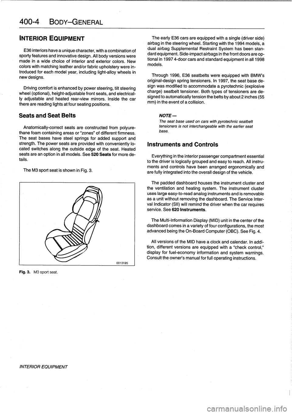
M3
sport
seat
is
shown
in
Fig
.
3
.
are
fully
integrated
into
the
overall
design
of
the
vehicle
.
Fig
.
3
.
M3
sport
seat
.
INTERIOR
EQUIPMENT
0013195
The
early
E36
cars
areequipped
with
a
single
(driver
side)
airbag
in
the
steering
wheel
.
Startingwith
the
1994
models,
a
dual
airbag
Supplemental
Restraint
System
has
been
stan-
dard
equipment
.
Side-impact
airbags
in
the
front
doors
are
op-
tional
in
1997
4-door
cars
and
standard
equipment
in
all
1998
models
.
Through
1996,
E36
seatbelts
were
equipped
with
BMW's
original-designspring
tensioners
.
In
1997,
the
seat
base
de-
sign
was
modified
to
accommodate
a
pyrotechnic
(explosive
charge)
seatbelt
tensioner
.
Both
types
of
tensioners
arede-
signed
to
automatically
tension
the
belts
by
about2
inches(55
mm)
in
the
event
of
a
collision
.
The
padded
dashboard
houses
the
instrument
cluster
and
the
ventilation
and
heating
system
.
The
instrument
cluster
uses
large
easy-to-read
analog
instruments
and
is
removable
as
a
unit
without
removing
the
dashboard
.
The
Service
Inter-
val
Indicator
(SII)
will
remind
the
driver
when
thecar
requires
service
.
See
620
Instruments
.
The
Multi-Information
Display
(MID)
unit
in
thecenter
of
the
dashboard
comes
in
a
variety
of
four
configurations,
the
most
advanced
being
the
On-Board
Computer
(OBC)
.
See
Fig
.
4
.
Al¡
versions
of
the
MID
have
a
clock
and
calendar
.
In
addi-
tion,
different
versions
areequipped
with
a
"check
control,"
display
for
fuel-economy
information
and
system
warnings
.
Consult
the
owner's
manual
for
fui¡
operating
instructions
.
Page 355 of 759
002262
In
this
system,
three
microswitches
are
operated
via
the
door
lock
cylinder
at
each
front
door
.
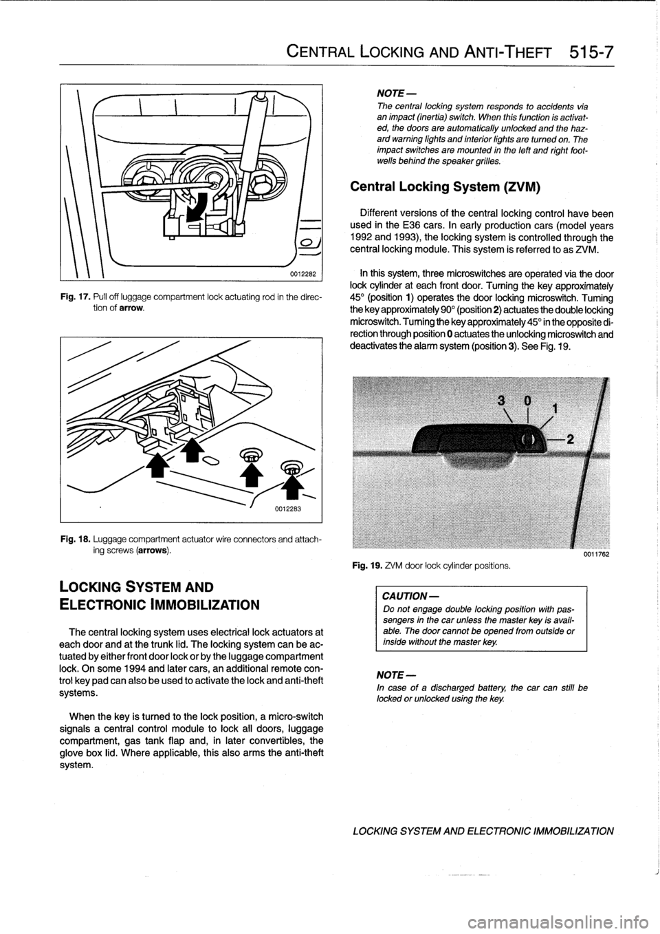
Turning
the
key
approximately
Fig
.
17
.
Pufl
off
luggage
compartment
lock
actuating
rod
in
the
direc-
45°
(position
1)
operates
the
door
locking
microswitch
.
Tuming
tionof
arrow
.
the
key
approximately
90°
(position2)
actuates
the
double
locking
microswitch
.
Tuming
the
key
approximately
45°
in
the
opposite
di-
rection
through
position
0
actuates
the
unlocking
microswitch
and
deactivates
the
alarm
system
(position3)
.
See
Fig
.
19
.
Fig
.
18
.
Luggage
compartment
actuatorwire
connectors
and
attach-
ing
screws
(arrows)
.
LOCKING
SYSTEM
AND
ELECTRONIC
IMMOBILIZATION
The
central
locking
system
uses
electrical
lock
actuators
at
each
door
and
at
the
trunk
lid
.
The
locking
system
can
be
ac-
tuated
by
either
front
door
lock
or
by
the
luggage
compartment
lock
.
Onsome
1994
and
later
cars,
an
additional
remote
con-
trol
keypadcan
also
be
used
to
activate
the
lock
and
anti-theft
systems
.
When
the
key
is
tuned
to
the
lock
position,
a
micro-switch
signals
a
central
control
module
to
lock
all
doors,
luggage
compartment,
gas
tank
flap
and,
in
later
convertibles,
the
glove
box
lid
.
Where
applicable,
this
also
arms
the
anti-theft
system
.
CENTRAL
LOCKING
AND
ANTI-THEFT
515-7
NOTE-
The
central
locking
system
responds
to
accidents
vía
animpact
(inertia)
switch
.
When
this
function
ís
activat-
ed,
the
doors
are
automatically
unlocked
and
the
haz-
ard
warning
lights
and
interiorlights
are
turned
on
.
The
impact
switches
are
mounted
in
the
left
and
right
foot-
wells
behind
the
speaker
grilles
.
Central
Locking
System
(ZVM)
Different
versions
of
the
central
locking
control
havebeen
used
in
the
E36
cars
.
In
early
production
cars
(model
years
1992
and
1993),
the
locking
system
is
controlled
through
the
central
locking
module
.
This
system
is
referred
to
as
ZVM
.
Fig
.
19
.
ZVM
door
lock
cylinderpositíons
.
CAUTION-
Do
not
engage
double
locking
position
with
pas-
sengers
in
the
car
unless
the
master
key
isavail-
able
.
The
door
cannotbe
opened
from
outside
orinside
without
the
master
key
.
NOTE-
In
case
of
a
discharged
battery,
the
car
can
still
be
locked
orunlocked
using
the
key
.
0011762
LOCKING
SYSTEM
AND
ELECTRONIC
IMMOBILIZATION
Page 371 of 759
GENERAL
.
...
.
.
.
......
.
.
.
.
.
.
.
.
.
......
541-1
Visor
Latch
Plate
.....
.
....
.
.
.
.
.
...
.
...
.541-4
Visor
Latch
..
.
............
.
.
.
..........
541-4
MANUAL
CONVERTIBLE
TOP
.
.
.
.
...
.
..
541-1
Visor
Latch
Motor
...
.......
.
.
.
..
........
541-5
Visor
Latch
Plate
.
.
......
.
.
.
...
.
.
.
.
.
.
.
..
541-1
Convertible
top
and
frame,
replacing
........
541-5
VisorLatch
.
.
.
.
.
.
.
.
..........
.
.....
.
.
.541-1
Convertible
top
drive
motor,
replacing
......
541-7
Convertible
Top
Lid
Release
Mechanism
.
.
.
.
541-2
Convertible
Top
Emergency
Operation
.....
.541-7
Convertible
top
and
frame,
replacing
....
.
.
.
541-2
Convertible
Top
Lid
.
.
.
.
...........
.
.....
541-9
POWER
CONVERTIBLE
TOP
.
.
.
.
....
.
.
.
541-2
ROLLOVER
PROTECTION
SYSTEM
..
.
.
541-9
FrontLatching
Mechanism
.
.
.
.
.
.
.
.
......
.
541-4
GENERAL
The
convertible
top
comes
in
three
versions
:
a
manually
op-erated
top,
a
semi-automatic
power
top
and
a
fully
automatic
power
top
.
NOTE-
The
convertible
top
control
module
(CVM)
is
located
behind
the
left
rearside
trim
panel
.
For
the
location
of
other
convertible
top
electric
components
see610
Electrical
Component
Locations
.
The
rear
window
in
the
convertible
models
is
made
of
a
strong,
flexible
vínyl
which
is
available
separately
.
Replace-
ment
of
the
rear
window
is
not
covered
in
this
manual
.
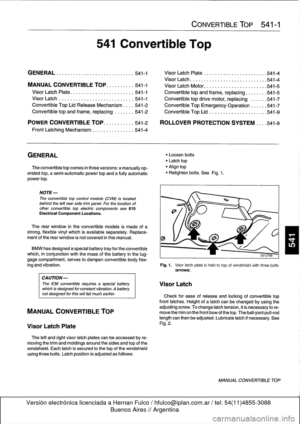
The
left
and
right
visor
latch
plates
can
be
accessed
by
re-
moving
the
trim
and
moldings
around
the
sides
and
top
of
the
windshield
.
Each
latch
is
secured
to
thetop
of
the
windshield
usingthree
bolts
.
Latch
position
is
adjusted
as
follows
:
541
Convertible
Top
CONVERTIBLE
TOP
541-1
"
Loosen
bolts
"
Latch
top
"
Align
top
"
Retighten
bolts
.
See
Fig
.
1
.
BMW
has
designed
a
specialbattery
tray
for
the
convertible
which,
in
conjunction
with
the
mass
of
the
battery
in
the
lug-
gage
compartment,
serves
to
dampen
convertible
body
flex
ing
and
vibration
.
Fig
.
1.
Visor
latchplate
is
held
to
top
of
windshieldwith
three
bolts
(arrows)
.
CAUTION-
The
E36
convertible
requires
a
specialbattery
VisorLatch
which
is
designed
for
constant
vibration
.
A
battery
not
designed
forthis
will
fa¡¡
much
earlier
.
Check
for
ease
of
release
and
locking
of
convertible
top
front
latches
.
Height
of
a
latch
can
be
changed
by
using
the
adjusting
screw
.
To
change
latch
tension,
it
is
necessary
to
re-
MANUAL
CONVERTIBLE
TOP
move
the
trim
on
the
front
bow
of
thetop
.
The
ball-joint
pull-rod
length
can
then
be
adjusted
.
Lubricate
latch
if
necessary
.
See
Visor
Latch
Plate
Fig
.
2
.
MANUAL
CONVERTIBLE
TOP
Page 372 of 759
541-2
CONVERTIBLE
TOP
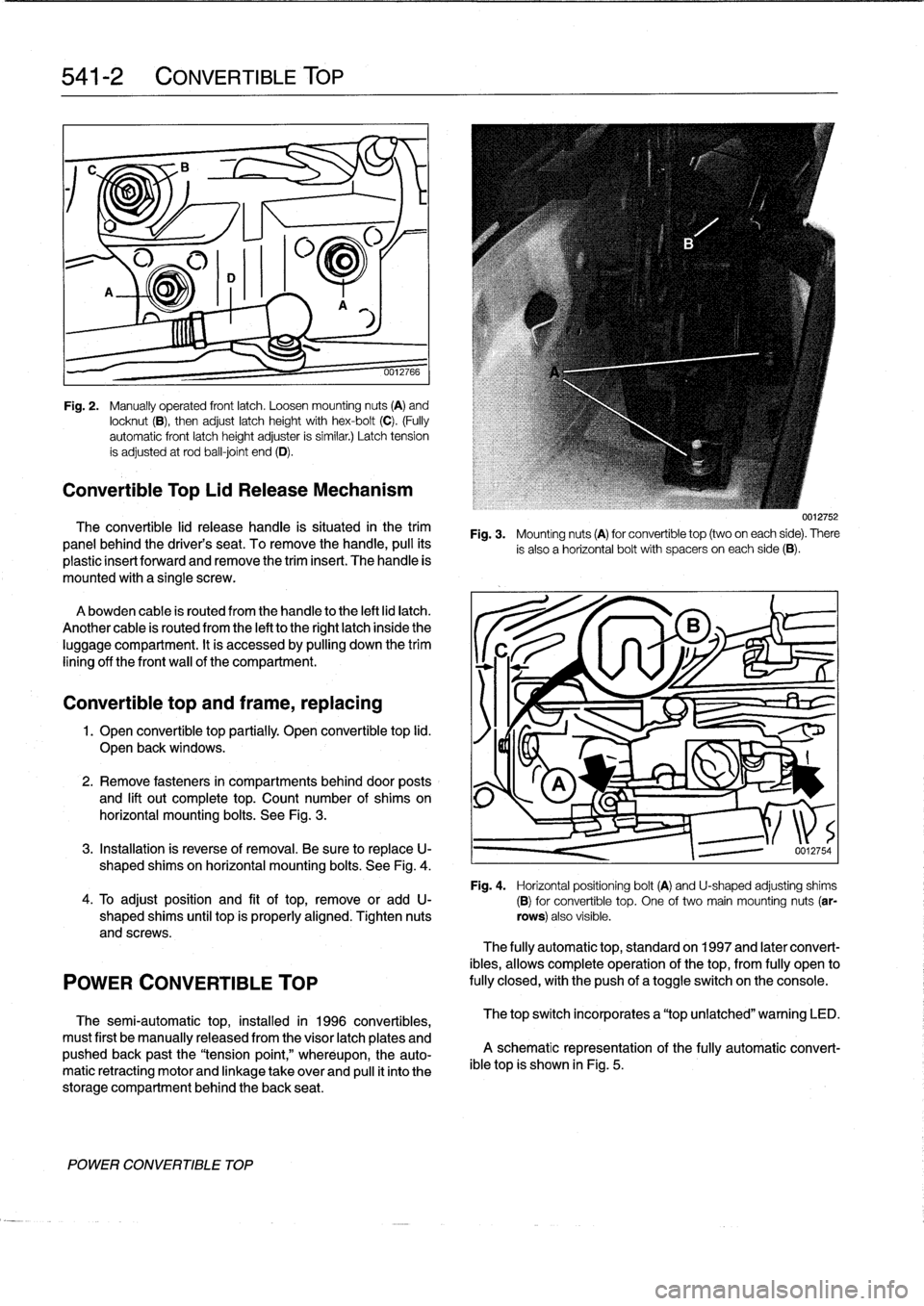
Fig
.
2
.
Manually
operated
frontlatch
.
Loosen
mounting
nuts
(A)
and
locknut
(B),
then
adjust
latch
height
with
hex-bolt
(C)
.
(Fully
automatic
front
latch
height
adjuster
is
similar
.)
Latch
tension
ís
adjusted
at
rod
ball-joint
end
(D)
.
Convertible
Top
Lid
Release
Mechanism
The
convertible
lid
release
handle
is
situated
in
the
trim
panel
behind
the
driver's
seat
.
To
remove
thehandle,
pull
its
plastic
insert
forward
and
remove
the
triminsert
.
The
handle
is
mounted
with
a
single
screw
.
Abowden
cable
is
routed
from
the
handle
to
the
left
lid
latch
.
Another
cable
is
routed
from
the
left
tothe
right
latch
inside
the
luggage
compartment
.
It
is
accessed
by
pulling
down
the
trim
lining
off
the
front
wall
of
the
compartment
.
Convertible
top
and
frame,
replacing
1
.
Open
convertible
top
partially
.
Open
convertible
top
lid
.
J
I~I~KX
Open
back
windows
.
_
v
2
.
Remove
fasteners
in
compartments
behind
door
posts
and
lift
out
complete
top
.
Count
number
of
shims
on
horizontal
mounting
bolts
.
See
Fig
.
3
.
3
.
Installation
is
reverse
of
removal
.
Be
sure
to
replaceU-
shaped
shims
on
horizontal
mounting
bolts
.
See
Fig
.
4
.
Fig
.
4
.
Horizontal
positioning
bolt(A)
and
U-shaped
adjusting
shims4
.
To
adjust
position
and
fit
oftop,
remove
or
add
U-
(B)for
convertible
top
.
One
of
two
main
mounting
nuts
(ar
shaped
shims
until
top
is
properly
aligned
.
Tighten
nuts
rows)
also
visible
.
and
screws
.
POWER
CONVERTIBLE
TOP
The
semi-automatic
top,
installed
in
1996
convertibles,
must
first
be
manually
released
from
the
visor
latch
plates
and
pushed
back
past
the
"tension
point,"
wheréupon,
the
auto-
matic
retracting
motor
and
linkage
take
over
and
pull
it
into
the
storage
compartment
behind
the
back
seat
.
POWER
CONVERTIBLE
TOP
Fig
.
3
.
Mounting
nuts
(A)
for
convertible
top
(two
oneach
side)
.
There
is
also
a
horizontal
bolt
with
spacers
oneach
side
(B)
.
0012754
The
fully
automatic
top,
standard
on
1997
and
later
convert-
ibles,
allows
complete
operation
of
the
top,
from
fully
open
to
fully
closed,withthe
push
of
atoggleswitch
on
the
console
.
The
top
switch
incorporates
a
"top
unlatched"
warning
LED
.
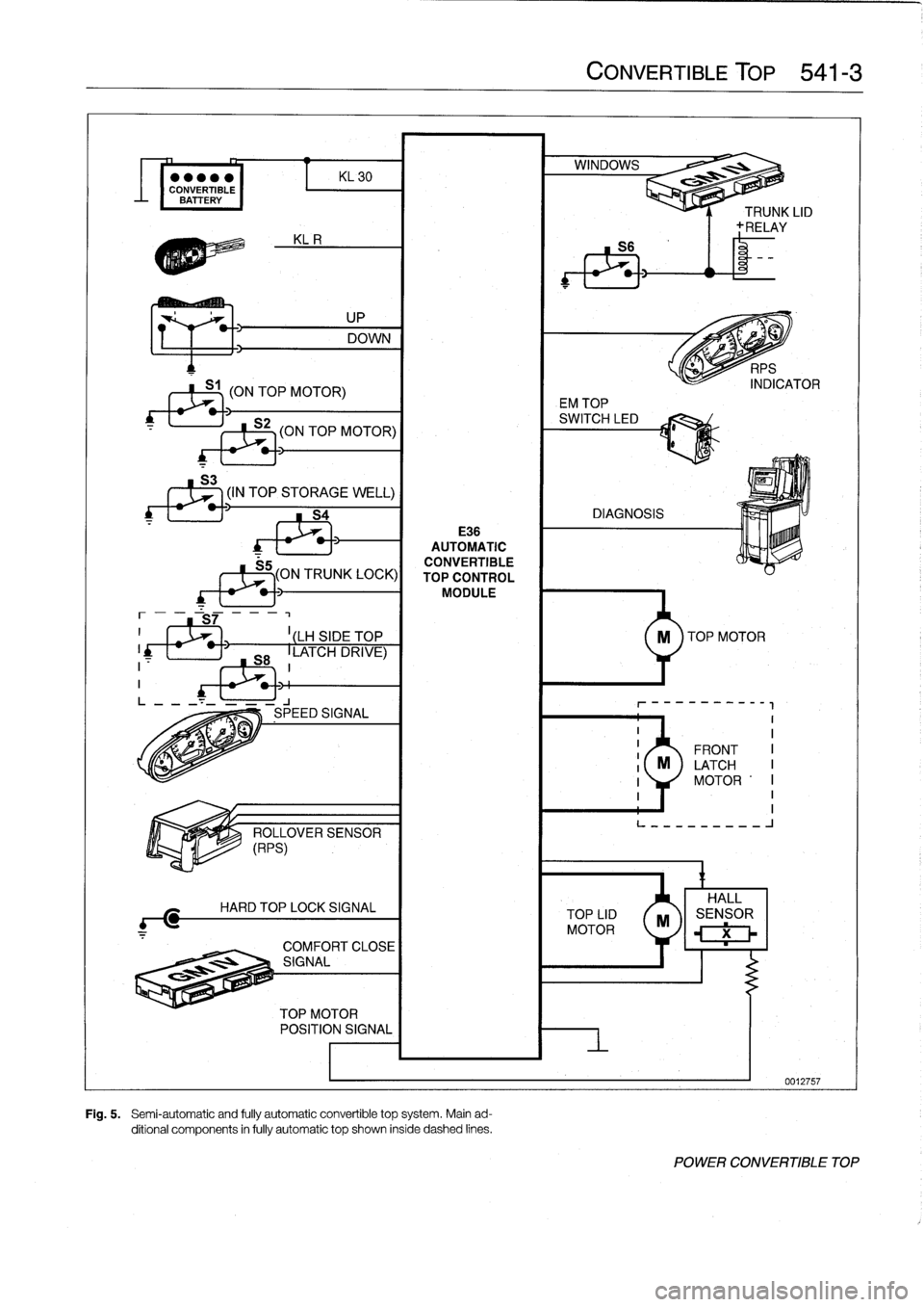
A
schematic
representation
of
the
fully
automatic
convert-
ible
top
is
shown
in
Fig
.
5
.
Page 373 of 759
KL
30
CONVERTIBLE
BATTERY
(ON
TOP
MOTOR)
UP
DOWN
S2
-I
(ON
TOP
MOTOR)
(IN
TOP
STORAGE
WELL)
S4
E36
AUTOMATIC
CONVERTIBLE
S5
(ON
TRUNK
LOCK)I
TOP
CONTROLMODULE
I
LH
SIDE
TOP
LATCH
DRIVE)
1
M-4
m
í
A
7--
Offi-
Íl
ít~~
ENSOR
H
ARD
T
OP
LOCK
SIGNAL
O
1~~11
:i
q
SIGNAL
TOP
MOTOR
POSITION
SIGNAL
Fig
.
5
.
Semi-automatic
and
fully
automatic
convertible
top
system
.
Main
ad-
ditional
components
in
fully
automatic
top
shown
inside
dashed
lines
.
CONVERTIBLE
TOP
541-3
TOP
LID
MOTOR
EM
TOP
n
~
ll
í
9
.1
-----------
II
II
FRONT
I
M
LATCH
I
1
MOTOR
'I
I
1I
L---------
J
X
POWER
CONVERTIBLE
TOP
Page 374 of 759
541-
4
CONVERTIBLE
TOP
Folding
roof
Frontlatches
Convertible
topframe
i
Lower
mounting
pata
Horizontal
positioning
~~-
bolt
Manual
front
8
e
latch
1
handle
~
O
Visor
latchplata
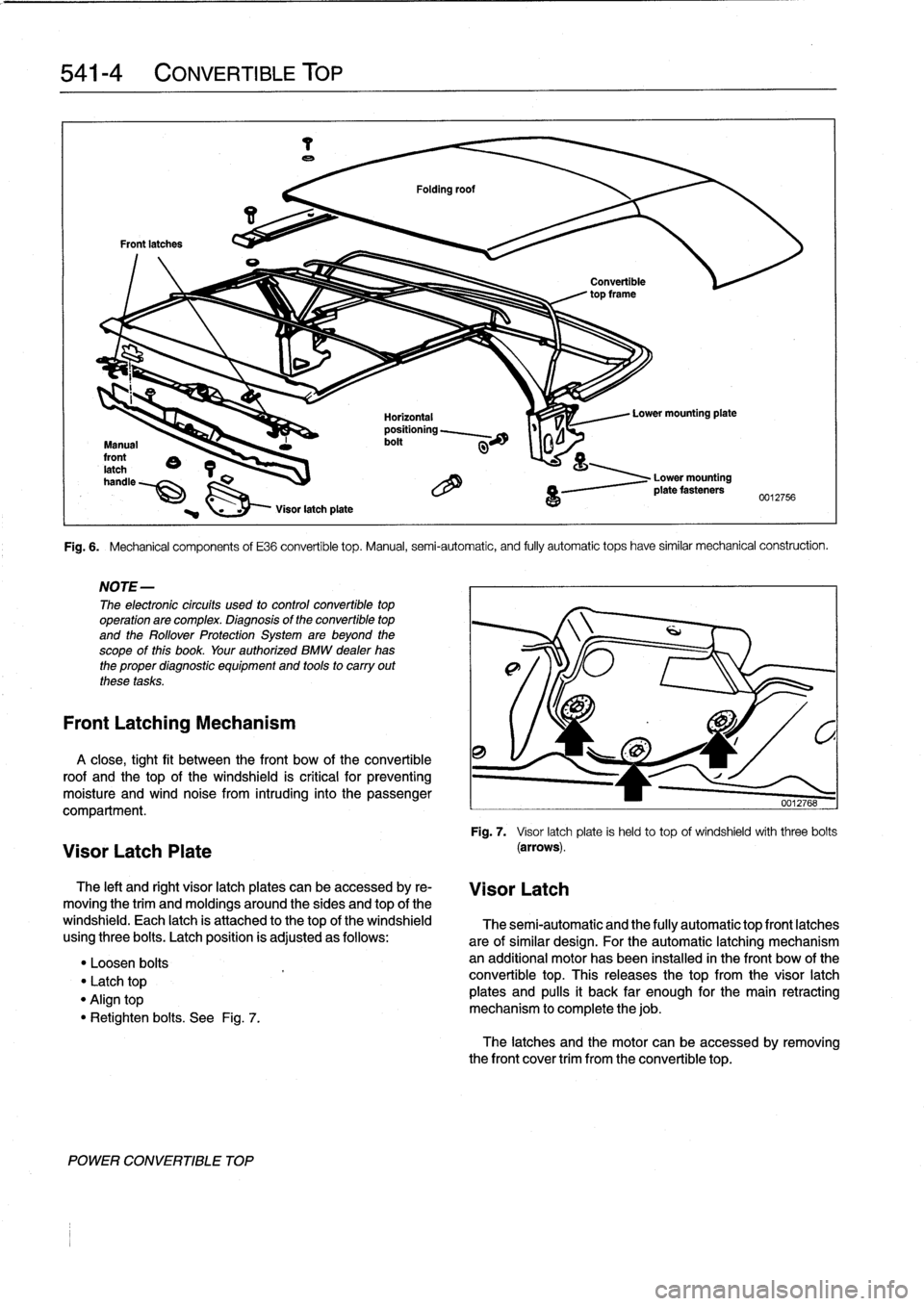
Fig
.
6
.
Mechanical
components
of
E36
convertible
top
.
Manual,
semi-automatic,
and
fully
automatic
tops
have
similar
mechanical
construction
.
NOTE-
The
electronic
circuits
used
to
controlconvertible
top
operation
arecomplex
.
Diagnosis
of
the
convertible
top
and
the
Rollover
Protection
System
are
beyond
the
scope
of
this
book
.
Your
authorized
BMW
dealer
has
the
proper
diagnostic
equipment
and
tools
to
carry
out
these
tasks
.
Front
Latching
Mechanism
A
close,
tight
fit
between
the
front
bow
of
the
convertible
roof
and
the
top
of
the
windshield
is
critical
for
preventing
moisture
and
wind
noise
from
intruding
into
the
passenger
compartment
.
Visor
Latch
Plate
The
left
and
right
visor
latch
plates
can
be
accessed
by
re-
moving
the
trim
and
moldings
aroundthe
sides
and
top
of
the
windshield
.
Each
latch
is
attached
to
thetop
of
the
windshield
using
three
bolts
.
Latch
position
is
adjusted
as
follows
:
"
Loosen
bolts
Latch
top
"
Align
top
"
Retighten
bolts
.
See
Fig
.
7
.
POWER
CONVERTIBLE
TOP
4
a
0012756
Visor
Latch
0012768
Fig
.
7
.
Visor
latchplate
is
heldto
top
of
windshieldwiththreebolts
(arrows)
.
The
semi-automatic
and
the
fully
automatic
top
front
latches
are
of
similar
design
.
For
the
automatic
latching
mechanism
an
additional
motor
has
been
installed
in
the
front
bow
of
the
convertible
top
.
This
releases
the
top
from
the
visor
latch
plates
and
pulís
it
back
far
enough
for
the
main
retracting
mechanism
to
complete
thejob
.
The
latches
and
the
motor
can
be
accessed
byremovingthe
front
cover
trim
from
the
convertible
top
.