automatic BMW M3 1998 E36 Manual PDF
[x] Cancel search | Manufacturer: BMW, Model Year: 1998, Model line: M3, Model: BMW M3 1998 E36Pages: 759
Page 447 of 759
GENERAL
E36
cars
are
equipped
with
integrated
automatic
heating
and
air
conditioning
systems
.
Many
of
the
procedures
given
in
this
repair
group
require
that
the
A/C
refrigerant
charge
be
evacuated
using
specialized
equipment
.
See
A/C
System
Warningsand
Cautions
later
in
this
repair
group
.
HEATER
AND
CONTROLS
Blower
motor,
removing
and
installing
NOTE-
On
6-cylinder
cars,
the
plastic
top
enginecover
and
fuel
rail
covermustbe
removed
.
The
fuel
injectorhamess
re-
taining
screws
must
be
removed
and
the
harness
set
aside
.
The
engine
control
module
(ECM)
cover
must
be
removed,
the
control
unit
connectors
unplugged
and
the
harness
pulled
out
of
the
way
.
See
130
Fuel
Injection
.
1
.
Disconnect
negative
(-)
cable
from
battery
.
2
.
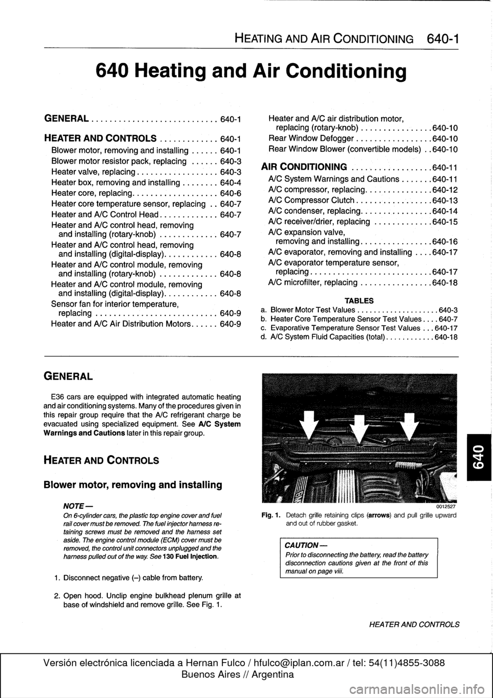
Open
hood
.
Unclip
engine
bulkhead
plenum
grille
at
base
of
windshíeld
and
remove
grille
.
See
Fig
.
1
.
HEATING
AND
AIR
CONDITIONING
640-1
640
Heating
and
Air
Conditioning
GENERAL
.
...
.
....
.
.
.
.
.
.
.
.
.
.......
.
.
.
640-1
Heater
andA/C
air
distribution
motor,
replacing(rotary-knob)
.
.
...
.
.
.
.......
.
640-10
HEATER
AND
CONTROLS
.
.....
.
.
.
.
.
.
.640-1
Rear
Window
Defogger
.
.
.
.
.
.
.
.
.
.
...
.
.
.
640-10
Blower
motor,
removing
and
installing
.
.
.
.
.
.
640-1
Rear
Window
Blower
(convertible
models)
.
.640-10
Blowermotor
resistor
pack,
replacing
.
.
.
.
.
.
640-3
AIR
CONDITIONING
.
.
.
.
.
.
.
.
.
.
.
.
.
.
.
.
.
.
640-11
Heater
valve,
replacing
...........
.
.
.
.
.
.
.
640-3
Heater
box,
removing
and
installing
.
.
.
.
.
.
.
.
640-4
A/CSystem
Warnings
and
Cautions
.
.
.
.
.
.
:640-11
Heater
core,
replacing
.....
.
.
:
....
.
.
.
.
.
.
.
640-6
A/C
compressor,
replacing
.
.
::.
:
:
.
.
.
.
.
.
.
.640-12
Heater
core
temperature
sensor,
replacing
.
.
640-7
A/C
Compressor
Clutch
.
.
.
.
.
.
.
:
.
.
.
.
.
.
.
.
.
640-13
Heater
andA/C
Control
Head
.
.
....
.
.....
.
640-7
A/C
condenser,
replacing
.
.
.
.
.
.
.
.
.
.
.
.
.
.
.
.
640-14
Heater
andA/C
control
head,
removing
A/C
receiver/drier,
replacing
.
.
.
.
.
.
.
.
.
.
.
.
.
640-15
and
installing
(rotary-knob)
.
.
....
.
......
640-7
A/C
expansion
valve,
Heater
andA/C
control
head,
removing
removing
and
installing
...
.
.....
.
.
.
.
.
.
.
640-16
and
installing
(digital-display)
.
.....
.
.....
640-8
A/C
evaporator,
removing
and
installing
.
.
..
640-17
Heater
andA/C
control
module,removing
A/C
evaporator
temperature
sensor,
and
installing
(rotary-knob)
.
.
...
.
.
.
.
.
.
.
.
640-8
replacing
.
.
.
.
.
.
..............
.
.
.
.
.
..
640-17
Heater
andA/C
control
module,removing
A/C
microfilter,
replacing
......
.
....
.
.
.
..
640-18
and
installing
(digital-display)
.
...
.
.
.
.
.
...
640-8
Sensor
fan
for
interior
temperature,
TABLES
replacing
.
.
.
....
.
.
.
.
.
.
.
.
.
.
.
.
.
.
.
.
.
.
.
.
640-9
a
.
Blower
Motor
Test
Values
.........
...
.
.
......
640-3
Heater
andA/C
AirDistribution
Motors
.
.
.
.
.
.
640-9
b
.
Heater
Core
Temperature
Sensor
Test
Values
...
.640-7
c
.
Evaporative
Temperature
Sensor
Test
Values
...
640-17
d
.
A/C
System
Fluid
Capacities
(total)
..
..........
640-18
0012527
Fig
.
1
.
Detach
grille
retaining
clips
(arrows)
and
pull
grille
upward
and
out
of
rubbergasket
.
CAUTION-
Prior
to
disconnectiog
the
battery,
read
the
battery
disconnection
cautionsgiven
at
the
front
of
this
manual
onpage
viii
.
HEATER
AND
CONTROLS
Page 453 of 759
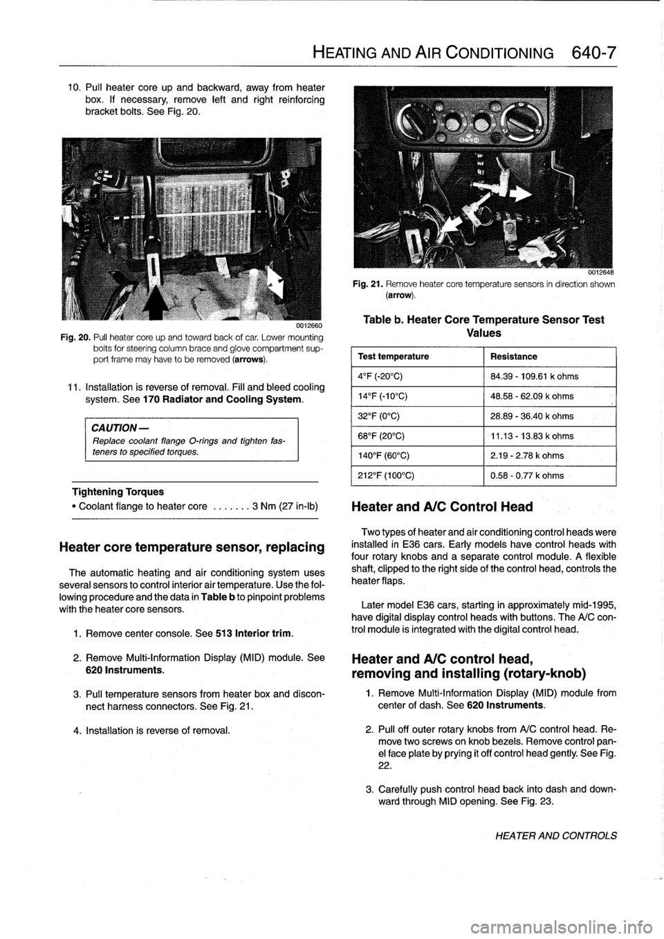
10
.
Pul¡
heater
core
up
and
backward,
away
from
heater
box
.
If
necessary,
remove
left
and
right
reinforcing
bracket
bolts
.
See
Fig
.
20
.
CAUTION-
Replace
coolant
flange
O-rings
and
tighten
fas-
teners
to
specified
torques
.
Tightening
Torques
1
.
Remove
center
console
.
See
513
Interior
trim
.
0012660
Fig
.
20
.
PA
heater
core
upand
towardback
of
car
.
Lower
mounting
bolts
for
steering
column
brace
and
glove
compartment
sup-
port
frame
may
have
to
be
removed
(arrows)
.
11
.
Installation
is
reverse
of
removal
.
Fill
and
bleed
cooling
system
.
See
170
Radiator
and
Cooling
System
.
"
Coolant
flange
to
heater
core
.
..
....
3
Nm
(27
in-lb)
Heater
andA/C
Control
Head
Heatercore
temperature
sensor,
replacing
The
automatic
heating
and
air
conditioning
systemuses
severa¡
sensors
to
control
interior
air
temperature
.
Use
the
fol-
lowing
procedure
and
the
data
in
Table
b
to
pinpoint
problems
with
theheater
core
sensors
.
2
.
Remove
Multi-Information
Display
(MID)
module
.
See
6201nstruments
.
HEATING
AND
AIR
CONDITIONING
640-7
0012648
Fig
.
21
.
Remove
heatercore
temperaturesensors
in
direction
shown
(arrow)
.
Table
b
.
Heater
CoreTemperatureSensor
Test
Values
Test
temperature
Resistance
4°F
(-20°C)
84
.39
-
109
.61
k
ohms
14
°
F
(-10°C)
48
.58
-
62
.09
k
ohms
32°F
(0°C)
28
.89
-
36
.40
k
ohms
68°F
(20°C)
11
.13
-
13
.83
k
ohms
140°F
(60°C)
2
.19
-
2
.78
k
ohms
212°F
(100°C)
0
.58
-
0
.77
k
ohms
Two
types
of
heater
and
aír
conditioning
control
heads
viere
installed
in
E36
cars
.
Early
models
have
control
heads
with
four
rotary
knobs
and
a
separate
control
module
.
A
flexible
shaft,
clipped
to
the
right
sideof
the
control
head,
controls
the
heater
flaps
.
Later
model
E36
cars,
starting
in
approximately
mid-1995,
have
digital
display
control
heads
with
buttons
.
The
A/C
con-
trol
module
is
integrated
with
the
digital
control
head
.
Heater
and
A/C
control
head,
removing
and
installing
(rotary-knob)
3
.
Pul¡
temperature
sensors
from
heater
box
and
discon-
1
.
Remove
Multi-Information
Display
(MID)
module
from
nect
harness
connectors
.
See
Fig
.
21
.
center
of
dash
.
See
620
Instruments
.
4
.
Installation
is
reverse
of
removal
.
2
.
Pul¡
off
outer
rotary
knobs
from
A/C
control
head
.
Re-
move
two
screwsonknob
bezels
.
Remove
control
pan-
el
face
plate
by
prying
it
off
control
head
gently
.
See
Fig
.
22
.
3
.
Carefully
push
control
head
back
into
dash
and
down-
ward
through
MID
opening
.
See
Fig
.
23
.
HEATER
AND
CONTROLS
Page 466 of 759
650-2
RADIO
"
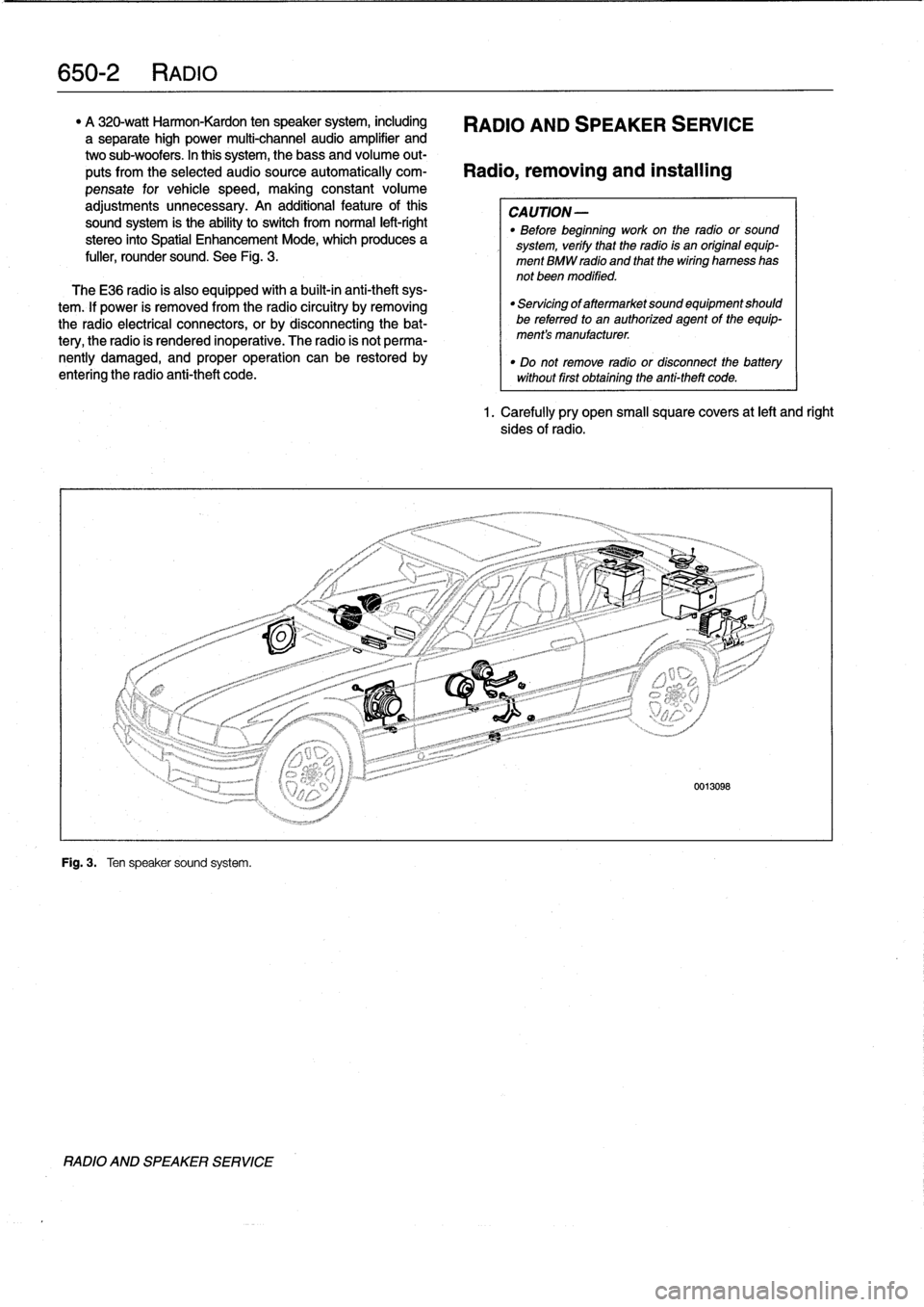
A
320-watt
Harmon-Kardon
ten
speaker
system,
including
RADIO
AND
SPEAKER
SERVICE
a
separate
high
power
multi-channel
audio
amplifier
and
two
sub-woofers
.
In
this
system,
thebass
and
volume
out-
puts
from
the
selected
audiosource
automatically
com-
Radio,
removing
and
installing
pensate
for
vehicle
speed,
making
constant
volume
adjustments
unnecessary
.
An
additional
feature
ofthis
CAUTION-
sound
system
is
the
ability
to
switch
from
normal
left-right
"
Before
beginning
work
on
the
radio
or
sound
stereo
into
Spatial
Enhancement
Mode,
which
produces
a
system,
verify
that
the
radio
is
an
original
equip-
fuller,
rounder
sound
.
See
Fig
.
3
.
ment
BMW
radio
and
that
thewiring
harness
has
not
been
modified
.
TheE36
radio
is
also
equipped
with
a
built-in
anti-theft
sys-
tem
.
lf
power
is
removed
from
the
radio
circuitry
by
removing
the
radio
electrical
connectors,
or
by
disconnecting
the
bat-
tery,
the
radio
is
rendered
inoperative
.
The
radio
is
not
perma-
nently
damaged,
and
proper
operation
can
be
restored
by
entering
the
radio
anti-theft
code
.
Fig
.
3
.
Ten
speaker
sound
system
.
RADIO
AND
SPEAKER
SERVICE
"
Servicing
of
aftermarket
sound
equipment
should
be
referredto
an
authorized
agent
of
the
equip-
ment's
manufacturer
.
"
Do
not
remove
radio
or
disconnect
the
batterywithout
first
obtaining
the
anti-theft
code
.
1.
Carefully
pry
open
small
square
covers
at
left
and
right
sides
of
radio
.
Page 470 of 759
650-
6
RADIO
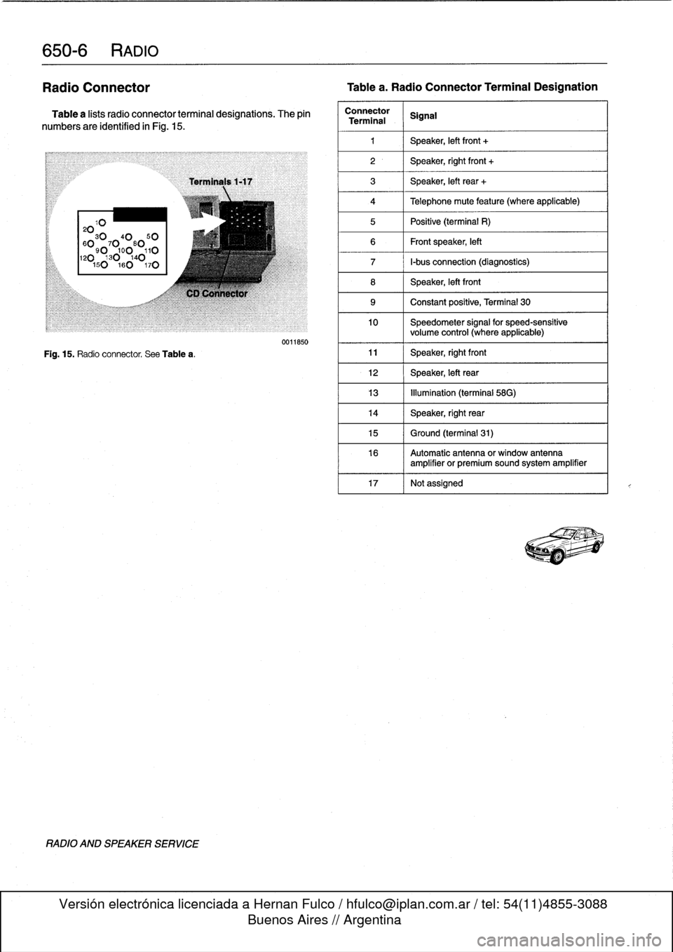
Radio
Connector
Tablea
.
Radio
Connector
Terminal
Designation
Table
a
lists
radio
connector
terminal
designations
.
The
pin
numbers
are
identified
in
Fig
.
15
.
20103040
50
60
90
7
0
0
80
110120130140150160
170
Fig
.
15
.
Radio
connector
.
See
Tablea
.
RADIO
AND
SPEAKER
SERVICE
Terminals
1-17
C1)
Connector
0011850
Connector
SignalTerminal
1
1
Speaker,
left
front
+
2
1
Speaker,
right
front
+
3
1
Speaker,
left
rear
+
4
1
Telephone
mute
feature
(where
applicable)
5
1
Positive
(terminal
R)
6
1
Frontspeaker,
left
7
1
I-bus
connection
(diagnostics)
8
Speaker,
left
front
9
1
Constant
positive,
Terminal
30
10
Speedometer
signal
for
speed-sensitive
volume
control
(where
applicable)
11
1
Speaker,
rightfront
12
1
Speaker,
left
rear
13
1
Illumination
(terminal
58G)
14
Speaker,
right
rear
15
1
Ground
(terminal
31)
16
Automatic
antenna
or
window
antenna
amplifier
or
premiumsound
system
amplifier
17
Notassigned
!'~_T-
Page 471 of 759
GENERAL
.
.
.....
.
.
.
.
.
.
.
.
.
............
720-1
REAR
SEATBELT
ASSEMBLY
...
.
....
.
.
720-4
Rear
seat
belt,
removing
and
installing
FRONT
SEATBELT
ASSEMBLY
.
.
.
.
.
.
.
.
720-2
(fixed
seat
back
models)
..
.
......
.
....
.
.720-4
Automatic
Front
Seat
Belt
Lock
Tensioners
.
.
720-2
Rear
seat
belt,
removing
and
installing
Mechanical
spring
tensioner,
disarming
.
...
.
720-2
(fold-downseat
back
models)
.
...
.
...
.
.
.
.
720-5
Front
seat
belt
reel,
removing
and
installing
.
.
720-3
Center
rear
lap-belt,
removing
and
installing
.
.720-5
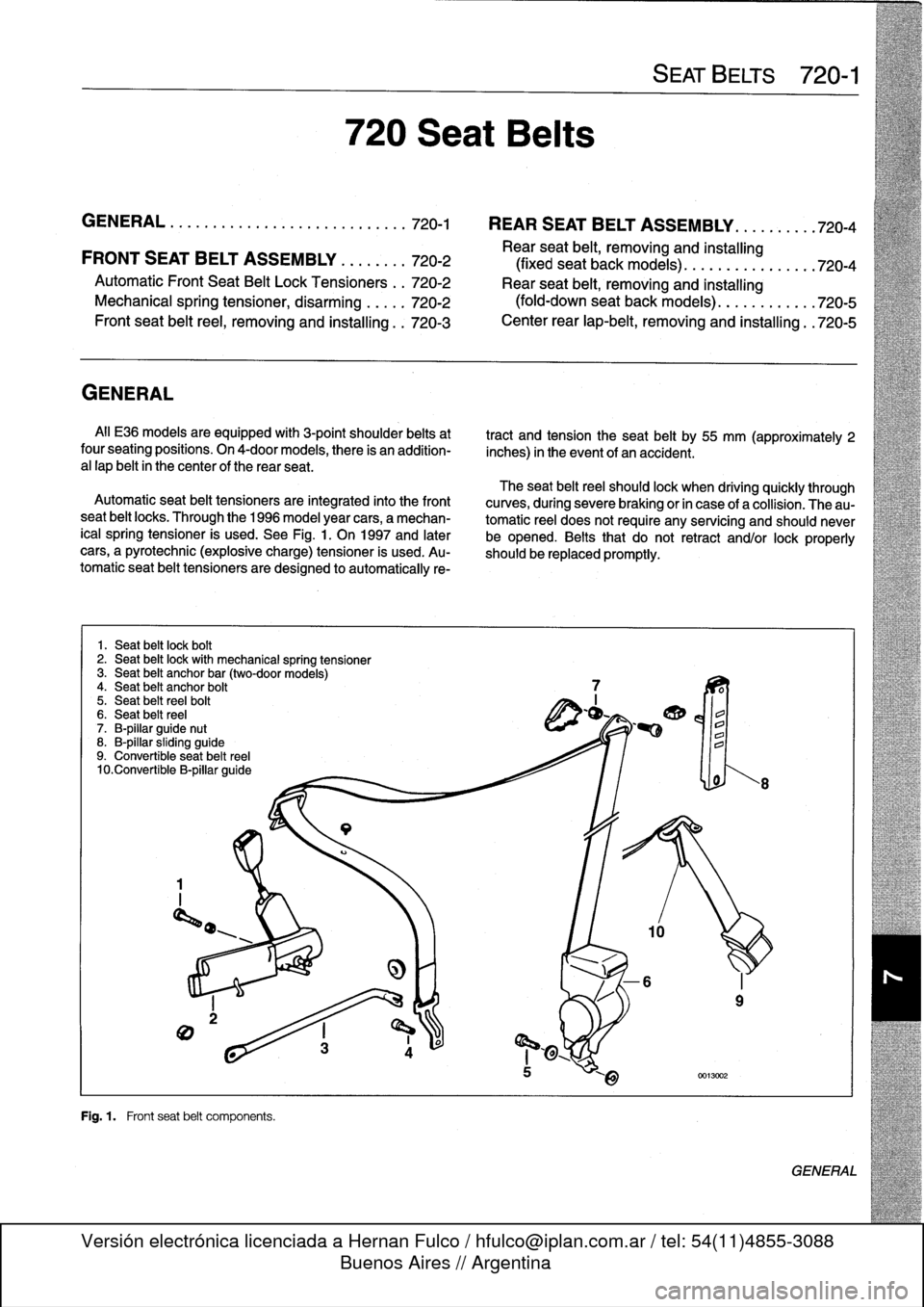
GENERAL
All
E36
models
are
equipped
with
3-point
shoulder
belts
at
tract
and
tension
the
seat
belt
by
55
mm
(approximately
2
four
seating
positions
.
On
4-doormodels,
there
is
an
addition-
inches)
in
the
event
of
an
accident
.
a
l
lap
belt
in
thecenter
of
the
rear
seat
.
The
seat
beltreel
should
lock
when
driving
quickly
through
Automatic
seat
belt
tensioners
are
integrated
into
the
front
curves,
during
severe
braking
or
in
case
of
a
collision
.
The
au-
seat
belt
locks
.
Through
the
1996
model
year
cars,
a
mechan-
tomatic
reel
does
not
require
any
servicing
and
should
never
¡cal
spring
tensioner
is
used
.
See
Fig
.
1.
On
1997
and
later
be
opened
.
Belts
that
do
not
retract
and/or
lockproperly
cars,
a
pyrotechnic
(explosive
charge)
tensioner
is
used
.
Au-
should
be
replaced
promptly
.
tomatic
seat
belt
tensioners
aredesigned
to
automatically
re-
1
.
Seat
belt
lock
boft
2
.
Seat
belt
lockwith
mechanical
spring
tensioner
3
.
Seat
belt
anchor
bar
(two-door
models)
4
.
Seat
belt
anchor
bolt
5
.
Seat
belt
reelbolt
6
.
Seat
belt
reel
7
.
B-pillar
guide
nut
8
.
B-pillar
sliding
guide
9
.
Convertible
seat
beltreel
10
.Convertible
B-pillar
guide
Fig
.
1
.
Front
seat
belt
components
.
720
Seat
Belts
SEAT
BELTS
720-1
GENERAL
Page 472 of 759
720-2
SEAT
BELTS
WARNING
-
"
For
maximum
protection
from
injury,
seat
belts
should
be
replaced
as
a
set
(including
all
hard-
ware),
if
they
are
subject
to
occupant
loading
in
a
collision
.
"
Seat
belts
should
not
be
modified
or
repaired
.
The
seat
belt
anchorage
points
should
not
be
changed
or
modified
.
"
Do
notbleach
or
dye
seat
belt
webbing
.
Webbing
that
is
severely
fadedor
re-dyed
will
not
meet
the
strength
requirements
of
a
collision
and
must
be
replaced
.
"
Seat
belts
shouldbe
periodically
inspected
for
webbing
defects
suchas
cuts
or
pulled
threads
.
FRONT
SEATBELT
ASSEMBLY
Automatic
Front
Seat
Belt
Lock
Tensioners
The
procedure
for
disabling
the
mechanical
spring
tension-
er
used
on
early
cars
is
covered
below
.
On
cars
with
thepyro-
technic(explosive
device)
tensioners,
the
orange
harness
connectorshould
be
removed
from
the
tensioner
any
time
the
seat
is
removed
.
WARNING
-
Both
the
mechanical
and
the
pyrotechnictensioners
are
powerful
devíces
and
shouldbehandled
with
extreme
care
.
Mechanical
spring
tensioner,
disarming
1
.
Remove
front
seat
.
See
520
Seats
.
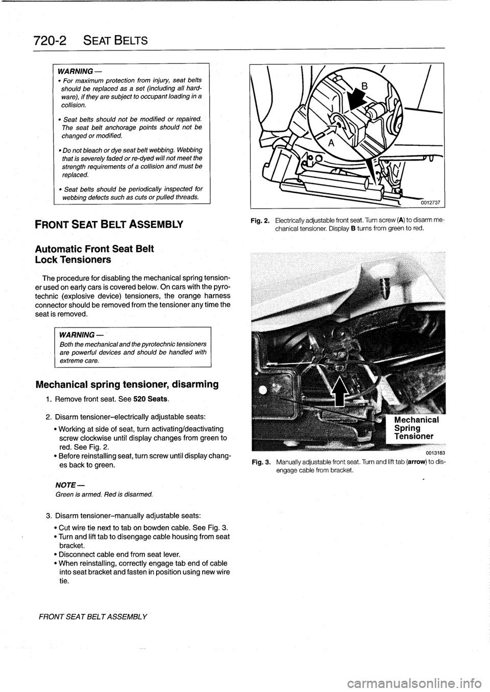
2
.
Disarm
tensioner-electrically
adjustableseats
:
"
Working
at
side
of
seat,
turn
activating/deactivating
screw
clockwise
until
display
changes
from
green
to
red
.
See
Fig
.
2
.
"
Before
reinstalling
seat,
turn
screw
until
display
chang-
esback
to
green
.
NOTE-
Green
is
armed
.
Red
is
disarmed
.
3
.
Disarm
tensioner-manually
adjustable
seats
:
"
Cut
wíre
tie
next
to
tab
on
bowden
cable
.
See
Fig
.
3
.
"
Turn
and
lift
tabto
disengage
cable
housing
from
seat
bracket
.
"
Disconnect
cable
end
from
seat
lever
.
"
When
reinstalling,
correctly
engage
tab
end
of
cable
into
seat
bracket
and
fasten
in
position
using
new
wíre
tie
.
FRONT
SEATBELT
ASSEMBLY
0012737
Fig
.
2
.
Electrically
adjustable
front
seat
.
Turn
screw
(A)
to
disarm
me-
chanical
tensioner
.
Display
B
tucos
from
green
to
red
.
F19
.3
.
Manuallyadjustablefrontseat
.Turnandlifttab(arrow)todis-
Page 485 of 759
GENERAL
This
section
contains
wiring
diagrams
for
1992
through
1998
BMW
3
Series
models
.
WARNING
-
On
cars
equipped
with
airbags,
special
precautions
apply
to
any
electrical
testing
or
repair
.
The
airbag
unit
is
an
explosive
device
and
must
be
handled
with
exterme
care
.
Before
starting
any
work
onan
airbag
equipped
car,
refer
to
the
warnings
and
cau-
tions
in
720
Seatbelts
and
721
Airbag
Systems
(SRS)
.
NOTE-
The
"
gear
position/neutral
safetyswitch
is
also
some-
timesreferred
to
as
the
automatic
transmission
range
switch
.
"
The
EWS
11
system
is
also
sometimes
referred
to
as
the
Driveaway
Protection
System
or
the
electronic
im-
mobilization
system
.
ELECTRICAL
WIRING
DIAGRAMS
ELE-1
Electrical
Wiring
Diagrams
GENERAL
.
.
.
.
.
.
.
.
.
................
.
.
.
ELE-1
Horns
.....
.
.....
.
.
.
....
.
.
.
.
.
...
.
.
ELE-153
Instrument
Panel
.
.
.
.
.
.
..............
ELE-165
ELECTRICAL
WIRING
DIAGRAMS
...
.
.
.
ELE-2
Interior
Lights/Illumination
.............
ELE-211
ABS
..............
.
.
.
.....
.
.....
ELE-117
Lumbar
Control
.
....................
ELE-247
ABS/AST
.............
.
.
.
...
.
.
.
.....
ELE-120
On-Board
Computer
..................
ELE-173
Airbag
(Supplemental
Restraint
System)
..
ELE-140
Park
Ventilation
.
.
.
...........
.
...
.
..
ELE-139
Air
Conditioning
and
Heating
.
.
.
.
.
.
.....
ELE-129
Power
Distribution
......
.
...
.
.
.
.
.
.
.
...
.
ELE-2
Anti-Theft
(Alpine)
..........
.
.
.
...
.
...
ELE-144
Power
Door
Locks
.
.
......
.
.
.
.
.
.
.
.
.
..
ELE-226
Anti-Theft
(EWS
II)
.
........
.
.
.
...
.
...
ELE-150
Power
Mirrors
...
.
.
.
......
.
.
.
.
.
.
.
.
.
..
ELE-241
Body
Computer
Module
.....
.
.....
.
...
ELE-176
Power
Seats
......
.
......
.
.
.
...
.
.
.
..
ELE-243
Charging
System
.
.
................
.
.
.
ELE-67
Power
Sunroof
.
.
.
.
.
.
.
...............
ELE-248
Convertible
Top
.
.
.
.
................
.
.
ELE-253
Power
Windows
.
.
.
.
.
.
.....
.
.........
ELE-231
Cruise
Control
..
.
.
.
...........
.
....
.
.
ELE-112
Radio/Cassette/CD/Speakers
..........
ELE-255
Data
Link
Connector
................
.
.
.
ELE-86
Rear
Window
Defogger
...............
ELE-160
Engine
Cooling
.......
.
.......
.
....
.
.
.
ELE-94
Shift
Interlock
.
.
.
.
.
.
.
.
...............
ELE-110
Engine
Management
...
.
.......
.
....
.
.
.
ELE-70
Starting
....
.
.
.
.
.
...
.
................
ELE-63
Exterior
Lights
........
.
.
.
.
.
.
.
.
.
......
ELE-194
Transmission
Electronics
.
..............
ELE-96
Ground
Distribution
....
.
.
.
.
.
.
.
.
.
.......
ELE-35
Warning
System
:
Chimes
.............
ELE-178
Headlights/Foglights
...
.
.
.
.
.
.
.
.
.
......
ELE-180
Wiper/Washer
.
.....
.
...............
ELE-155
Heated
Seats
........
.
.
.
.
.
.
.
.
.
......
ELE-245
ELECTRICAL
COMPONENT
LOCATIONS
Relayand
fuse
positions,
ground
locations
...........
.
.
.
.
.
.
.
.
.
................
seeRepair
Group
610
CAUTION-
Always
switchthe
ignition
off
and
disconnect
the
negative
(-)
battery
cablebefore
removing
any
electrical
components
.
"
Prior
to
disconnecting
the
battery,
read
the
bat-tery
disconnection
cautions
given
at
the
front
of
this
manual
on
page
viii
.
"
Connect
and
disconnect
ignition
system
wires,
multiple
connectors
and
ignition
test
equipment
leads
only
while
ignition
is
switched
off
.
-Always
switch
a
test
meter
to
the
appropiate
func-
tion
and
range
before
making
test
connections
.
"
All-Season
Traction
(AST)
is
also
referred
to
as
ASC
or
ASC+T
.
GENERAL
Page 489 of 759
EKE
Power
1992-
VIO
FROMIGNITION
U
VIO
FROM
IGNITI
ON
SWITCH
SWITCH
2S
(DIAGRAM3OF7)
31
(DIAGRAM3OF7)
I
-
______________-__________--
4
-_____________________I_-FRONT
POWER
O
3
3
3
3
i
14
8
8
B
18
7
26
-
4
4
I
i
I
I
i
-F-
I
i
I
-
,
I
,
I
I
F-,
ON
-BOARD
CHECKCONTROL
WIPER
WIPER
MOTOR
INSTRUMENT
BRAKELIGHT
CRUISE
CONTROL
CRUISE
CONTROL
COMPRESSOR
NORMALCOMPUTER
MODULE
RELAYRELAY
CLUSTER
SWITCH
MODULE
SWITCH
CONTROL
SPEEDRELAYRELAY
GRN
0
FROM
IGNITION
GRN
P
FROM
IGNITION
~I
I
VSWITCH
SWITCH
(DIAGRAM
30F7)
,~
(DIAGRAM
3OF7)
-------_-_____________________________________________~FRONT
POWER
TO
I
DISTRIBUTIONBOX
FUSE
F23
G
(DIAG
RAM
4
0F
7)
I
FUSE
FUSE
FUSE
FUSE
FUSE
'
F26
F24
F25
F26
-
F27
6A
10A
SA
ICA
5A
is
S
,0
12
,4
o3
>
CANADA
5
I
~
~
~
3
33
-
2
22
B
F
O
2
5
23
AUTOMATIC
I
I
I
3
1
I
TRANSMISSION
AUXILIARY
RANGESWITCH
I
-
I
I
-
I
I
-
I
CONNECTOR
MIRRORCONTROL
LIGHT
LOWBEAM
AUTOMATIC
PROGRAM
INSTRUMENT
SWITCHSWITCH
LIGHTRELAY
TRANSMISSION
SWITCH
CLUSTER
WIOEGSONLY
RANGESWITCH
FROM
___________-----1FRONTPOWER
FUSEF24
CI
DISTRIBUTION
BC
3
(DIAGRAM30F7)
FUSE
FUSEFUSE
F23
F22
F21
O
O
SA
SA
5A
DATA
LINK
6
j
2
I
CONNECTOR
REVERSING
LIGHTSWITCH
CANADA
O
"
-1993
ONLY
O4
4
4
1
S
B
3
B
53
4
I
v
I~
i
I
i
I
v
I
i
I
v
I
i
I
v
I
i
I
i
I
i
v
v
v
v
~
v
v
~
~
v
v
~
v
v
o
n
v
v
v
v
v
v
_I
INTEGRATED
COMBINATION
INSTRUMENT
REAR
JETHEATER
MULTI-
UNLOADER
DAYTIMERUNNING
LIGHT
ASSSLIP
ABSRELAY
CLIMATE
SWITCH
CLUSTER
DEFOGGER
THERMOSWITCH
FUNCTION
RELAY
LIGHTSCODING
SWITCH
CONTROL
REGULATION
RELAY
CLOCK
DIODE
MODULE
CONTROL
MODULE
64776
Page 492 of 759
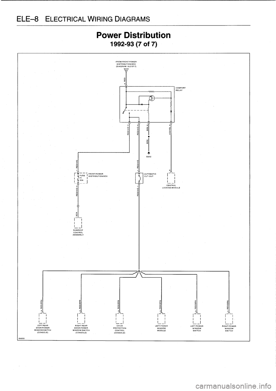
CAL
WIRING
DIAGR
Power
uis
1992-93
-
FROMFRONTPOWER
DISTRIBUTION
BOX
(DIAGRAM
1
&20F7)
1
3202
O
1
1
9
FRONTPOWER
AUTOMATIC
FUSE
I
DISTRIBUTIONBOX
CUT-OUT
I
I
I
F1
I
30
-J
2
1
CENTRAL
O
LOCKING
MODULE
II
I
-
I
I
SUNROOFCONTROL
ASSEMBLY
5
5
S
3
3
3
I
I
I
I
I
I
~
I
I
I
I
II
I
I
I
I
I
I
I
I
I
I
I.
LEFT
REAR
RIGHT
EAR
CHILD
LEFT
POWER
LEFT
POWER
RIGHTPOWER
000RPOWER
DOORPOWER
PROTECTION
WINDOW
WINDOW
WINDOWWINDOWSWITCH
WINDOWS
WITCH
CONTROL
MODULE
SWITCH
SWITCH
(CONSOLE)
(CONSOLE)
(CONSOLE)
64850
Page 495 of 759
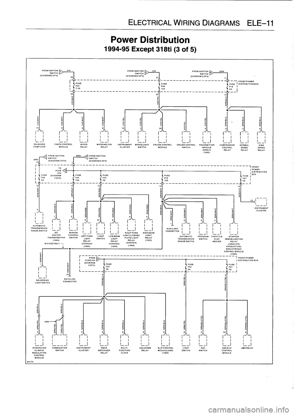
8317
4
FROMIGNITION
T
VIO
FROM
IGNITION
U
VIO
"I"
IGNITION
SWITCH
SWITCH
SWITCH
(DIAGRAM2OF5)
29
(DIAGRAM20F5)
31
(DIAGRAM20F5)
FROMIGNITION
GRIN
PROMIGNITION
SWITCH
SWITCH
(DIAGRAM20F5)
~(DIAGRAM20F5)
REVERSING
LIGHT
SW
TO
DATA
LINK
CONNECTOR
Power
Distribution
1994-95
Except
318ti
(3
of
5)
______________________________________________
-_-
FRONTPOWER
ELECTRICAL
WIRING
DIAGRAMS
ELE-11
3
FUSE
FUSE
I
DISTRIBUTION
BOX
F46
F18
I
L
>
t
141
6'
81
81
16/
11
261
j
2
4
q
I
I
I
I
I
I
I
i
I
Jll~~~
i
I
It
i
I
JJJ
...
i
-
i
-
i
-
i
-
i
--
I
I
I
1
I
II
I
I
I
I
I
I
I
I
I
I
I
I
I
I
I
I
I
I
I
I
I
I
I
ON-BOARD
CHECKCONTROL
WIPER
WIPERMOTOR
INSTRUMENT
BRAKELIGHT
CRUISE
CONTROL
CRUISECONTROL
TRANSMITTER
COMPRESSOR
NORMAL
HIGH
COMPUTERMODULE
RELAY
RELAY
CLUSTER
SWITCH
MODULE
SWITCH
MODULE
CONTROL
SPEEDSPEED
(EWSIN
RELAYRELAYRELAY
(1995)
,FRONT
(POWER
DISTRIBUTION
FUSE
FUSE
FUSE
(BOX
FUSE
I
F24
F25
F26
F27
10A
5A
10A
5q
I
------------------
-
-------
-
I
I
I
I
I
I
I
I
I
I
I
I
I
I
'
I
I
I
I
I
I
I
I
AUTOMATIC
"1"
TRANSMISSION
I
-
I
I
_
I
I
_
I
I
I
I
I
I
-)
I
_
I
AUXILIARY
RANGESWITCH
JETMIRROR
L
II
CONNECTORCONNECTOR
RIG
H7
PARK
HIGH
BEAM
I
I
I
I
HEATER
CONTROL
LEFT
PARK
LIGHT
LOWBEAM
LIGHT/LICENSE
LIGHT
AUTOMAT
IC
PROGRAM
THROTTLE
SWITCH
LIGHT
SWITCH
LIGHT
PLATE
LIGHT
RELAY
HROTTLE
STARTER
(
(1995)
TRANSMISSIONSWITCH
FLAP
IMMOBILIZATION
994)
RELAY
RELAYRELAY
A)
RANGESWITCH
HEATER
RELAY
WIOEGSONLV
--
I
-
(CANADA)
(CANADA)
(CANAD
(1994
LATE
(1894)
(1994)
(1
994
)
PRODUCTION)
SERVOTRONIC
CONTROLMODULE
(1995)
FROM
FRONTPOWER
I
FU
SEF24
I
DISTRIBUTIONBOX
I
(DIAGRAM
30F5)
FUSE
FUSE
FUSE
II
F23
F22
F21
I
5A
5A
5A
61
_I-
=
L
41
4,
1
91
8t
el
8),
51
531
I
I
I
I
I
I
I
I
I
I
I
I
I
I
I
I
I
I
I
I
I
i
I
I
I
I
I
I
I
I
I
I
I
I
I
I
I
I
I
I
I
I
I
II
_I
!
---
I
!
_I
!
_I
23
INTEGRATED
COMBINATION
INSTRUMENT
PEAR
MULTI-
UNLOADER
SLIP
CONTROL
LIGHT
ASC
ABSSLIP
ASS
RELAY
CLIMATE
SWITCH
CLUSTER
DEFOGGER
FUNCTION
RELAY
MODULE
(AB
S)
SWITCH
SWITCH
CONTROL
REGULATION
RELAY
CLOCK
(1995)
MODULE
CONTROL
MODULE
INSTRUMENT
CLUSTER