steering BMW M3 1998 E36 Manual PDF
[x] Cancel search | Manufacturer: BMW, Model Year: 1998, Model line: M3, Model: BMW M3 1998 E36Pages: 759
Page 478 of 759
721-2
AIRBAG
SYSTEM
(SRS)
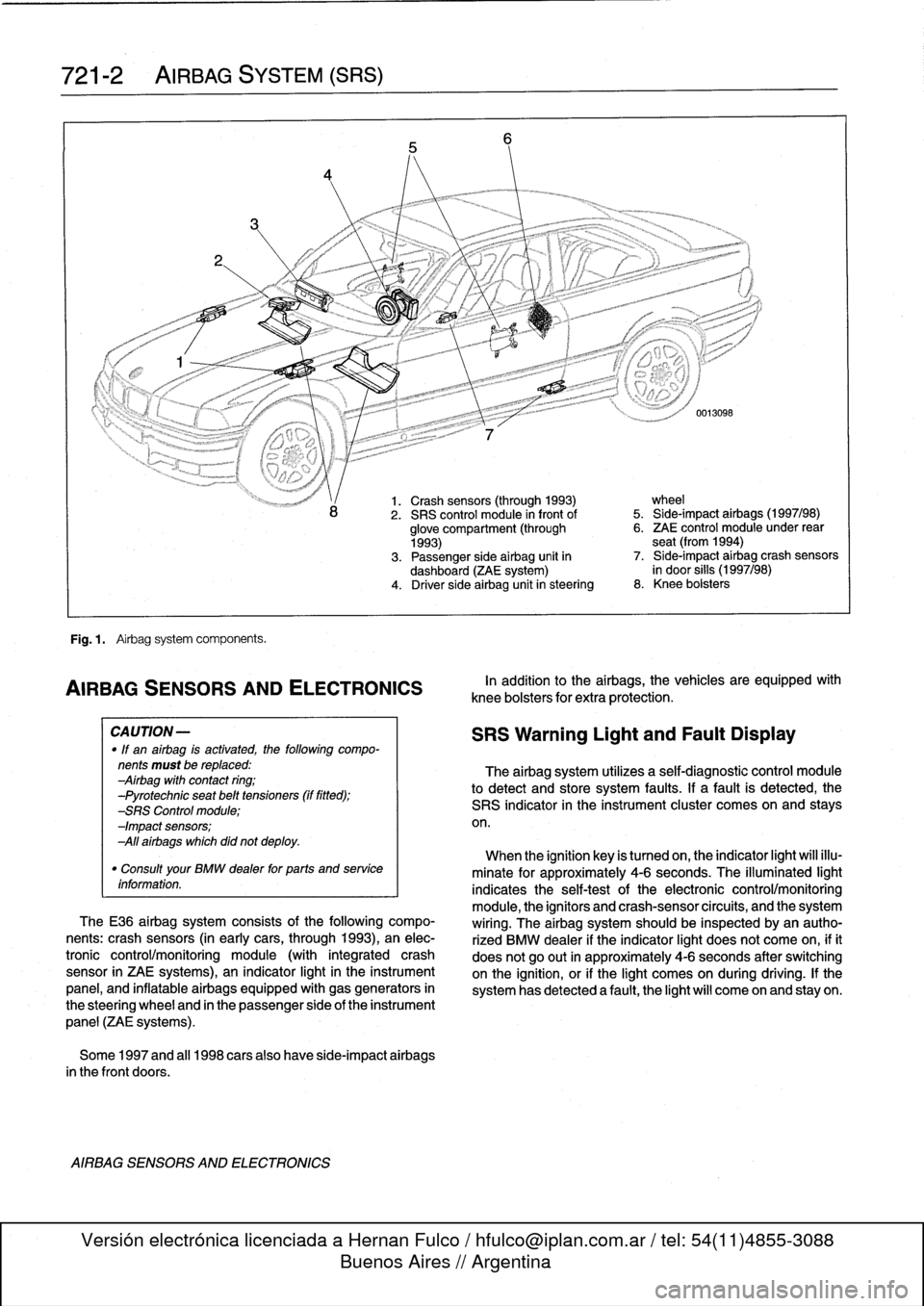
Fig
.
1
.
Airbag
system
components
.
AIRBAG
SENSORSAND
ELECTRONICS
CA
UTION-
"
If
an
airbag
is
activated,
the
following
compo-
nents
must
be
replaced
:
Airbag
with
contact
ring
;
-Pyrotechnic
seat
belt
tensioners
(if
fitted)
;
-SRS
Control
module
;
-Impact
sensors
;
All
airbags
which
did
not
deploy
.
"
Consult
your
BMW
dealer
for
parts
and
service
information
.
TheE36
airbag
system
consists
of
the
following
compo-
nents
:
crash
sensors
(in
earlycars,
through
1993),
an
elec-
tronic
control/monitoring
module
(with
integrated
crash
sensor
in
ZAE
systems),
an
indicator
light
in
the
instrument
panel,
and
inflatable
airbags
equipped
with
gas
generators
in
the
steering
wheel
and
in
the
passenger
side
of
the
instrument
panel
(ZAE
systems)
.
Some
1997
and
al¡
1998
carsalso
have
side-impact
airbags
in
the
front
doors
.
AIRBAG
SENSORS
AND
ELECTRONICS
1.
Crash
sensors
(through
1993)
wheel
2
.
SRS
control
module
in
front
of
5
.
Side-impact
airbags
(1997/98)
glove
compartment
(through
6
.
ZAE
control
module
under
rear
1993)
seat
(from
1994)
3
.
Passenger
side
airbag
unit
in
7
.
Side-impact
airbag
crash
sensors
dashboard
(ZAE
system)
in
door
silis
(1997/98)
4
.
Driver
side
airbag
unitin
steering
8
.
Knee
bolsters
In
addition
to
the
airbags,
the
vehicles
are
equipped
wíth
knee
bolsters
for
extra
protection
.
SRS
Warning
Light
and
Fault
Display
The
airbag
system
utilizes
a
self-diagnostic
control
module
to
detect
and
store
system
faults
.
If
a
fault
is
detected,
the
SRS
indicator
in
the
instrument
cluster
comes
on
and
stays
on
.
When
the
ignition
key
is
tumed
on,
the
indicator
light
will
illu-
minate
for
approximately
4-6
seconds
.
The
illuminated
light
indicates
the
self-testof
the
electronic
control/monitoring
module,
the
ignítors
and
crash-sensorcircuits,
and
the
system
wiring
.
The
airbag
system
should
be
inspected
byan
autho-
rized
BMW
dealer
if
the
indicator
light
does
not
come
on,
ifit
does
not
go
out
in
approximately
4-6
seconds
after
switching
onthe
ignition,
or
if
the
light
comes
on
during
driving
.
If
the
system
has
detected
a
fault,
the
light
will
come
on
and
stay
on
.
Page 479 of 759
1
.
Disconnect
negative
(-)
cable
from
battery
and
cover
negative
terminal
with
insulating
material
.
CA
UTION-
Prior
to
disconnectiog
the
battery,
read
the
battery
disconnection
cautions
given
at
the
front
of
this
manual
on
page
viii
.
2
.
Remove
driver
sideairbag
from
steering
wheel
.
See
Driver
side
airbag,
removing
and
installing
in
this
repair
group
.
3
.
With
wheels
facing
straight
ahead
and
steering
wheel
centered,
remove
steering
wheel
.
See320
Steering
and
Wheel
Alignment
.
4
.
Remove
contact
ring
cover
(flat
plastic
ring
containing
warning
text)
from
steering
wheel,
íf
applicable
.
5
.
Disconnect
ground
wire,
if
applicable
6
.
Lift
out
plastic
lock
from
steering
wheel,
if
applicable
.
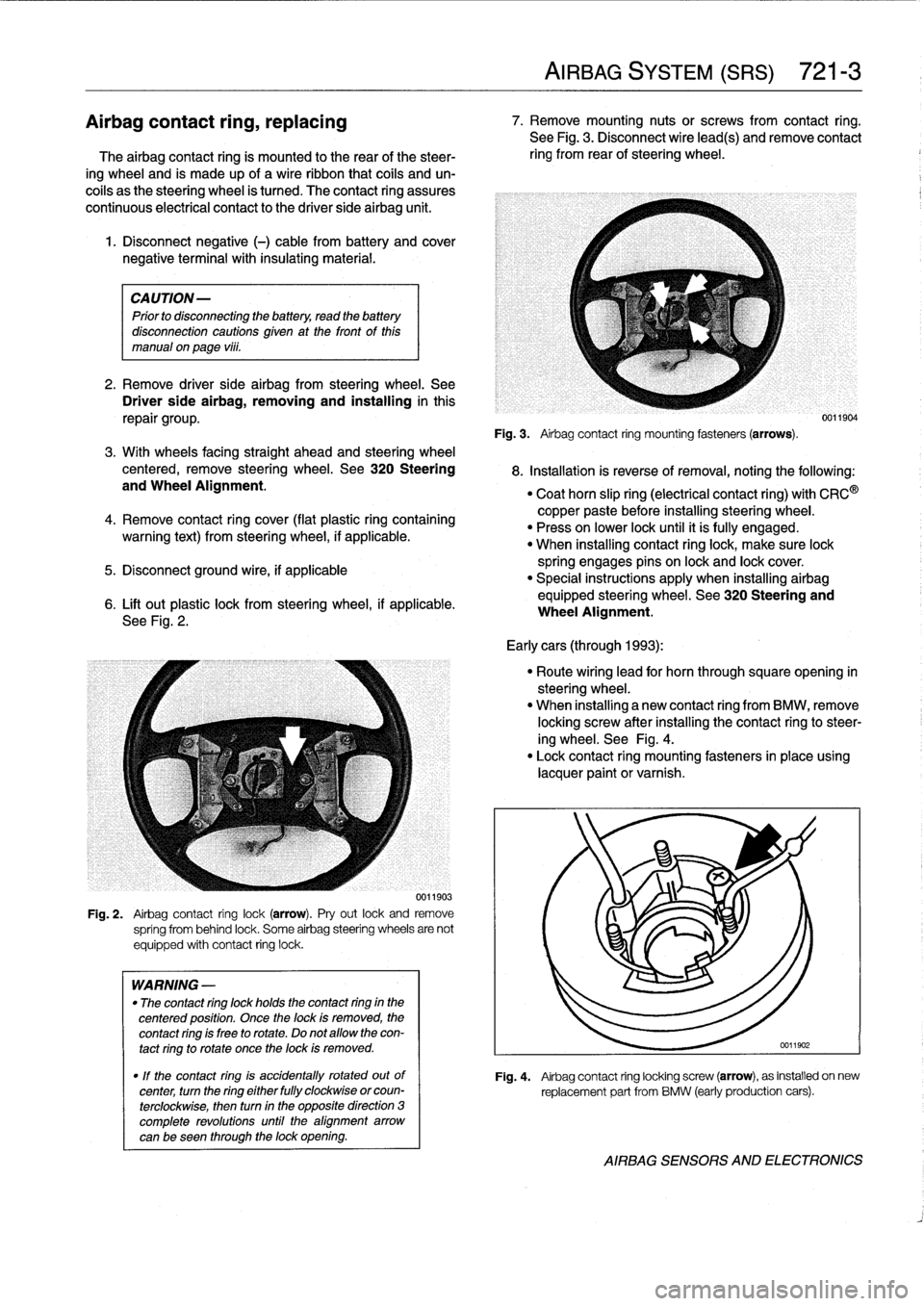
See
Fig
.
2
.
0011903
Fig
.
2
.
Airbag
contact
ring
lock(arrow)
.
Pry
out
lock
and
remove
spríng
from
behind
lock
.
Some
airbag
steering
wheels
are
not
equipped
with
contact
ring
lock
.
WARNING
-
"
The
contact
ring
lock
holds
the
contact
ring
in
the
centered
position
.
Once
the
lock
is
removed,
the
contact
ring
is
free
to
rotate
.
Do
not
allow
the
con-
tact
ring
to
rotate
once
the
lock
is
removed
.
"
If
the
contact
ring
is
accidentally
rotated
outof
center,
turn
the
ring
either
fully
clockwise
orcoun-
terclockwise,
then
turn
in
the
opposite
direction
3
complete
revolutions
until
the
alignment
arrow
canbe
seen
through
the
lock
opening
.
AIRBAG
SYSTEM
(SRS)
721-
3
Airbagcontact
ring,
replacing
7
.
Remove
mounting
nutsor
screws
from
contact
ring
.
See
Fig
.
3
.
Disconnect
wire
lead(s)
andremove
contact
The
airbag
contact
ring
is
mounted
to
the
rear
of
the
steer-
ring
from
rear
of
steering
wheel
.
ing
wheel
and
is
made
up
of
a
wireribbon
that
cofs
and
un-
coils
as
the
steering
wheel
is
tumed
.
The
contact
ring
assures
continuous
electrical
contact
to
the
driver
side
airbag
unit
.
Fig
.
3
.
Airbag
contact
ring
mounting
fasteners(arrows)
.
8
.
Installation
is
reverse
ofremoval,noting
the
following
:
"
Coat
horn
slip
ring
(electrical
contact
ring)
with
CRC
®
copper
paste
before
installing
steering
wheel
.
"
Press
on
lower
lock
until
it
ís
fully
engaged
.
"
When
installing
contact
ringlock,
make
sure
lock
spring
engages
pins
on
lock
and
lock
cover
.
"
Special
instructions
apply
when
installing
airbag
equipped
steering
wheel
.
See320
Steering
and
Wheel
Alignment
.
Early
cars
(through
1993)
:
"
Route
wiring
lead
for
horn
through
squareopening
in
steering
wheel
.
"
When
installing
a
new
contact
ring
from
BMW,
remove
locking
screw
after
installing
the
contact
ringto
steer-
ing
wheel
.
See
Fig
.
4
.
"
Lock
contact
ring
mounting
fasteners
in
place
using
lacquer
paint
or
varnish
.
0011904
Fig
.
4
.
Airbag
contact
ring
locking
screw
(arrow),
as
installed
on
new
replacement
part
from
BMW
(early
production
cars)
.
AIRBAG
SENSORS
AND
ELECTRONICS
Page 480 of 759
721-
4
AIRBAG
SYSTEM
(SRS)
CAUTION-
A
new
contact
ring
is
held
in
center
position
with
a
screw
.
This
locking
device
must
be
removed
after
contact
ring
is
installed
on
steering
wheel
.
See
Fig
.
4
.
Latercars
(1994
on)
:
"
Connect
ground
lead
at
contact
ring
.
"
When
installing
a
new
contact
ring
from
BMW,
remove
locking
pin
after
installing
contact
ring
to
steering
wheel
.
See
Fig
.
5
.
Airbag
crash
sensor,
replacing
Fig
.
5
.
Airbag
contact
ring
locking
pin
(arrows),
as
installed
on
new
replacement
part
from
BMW
(later
production
cars)
.
Contact
ring
mountíng
screws
shown
at
A
.
CAUTION-
Anew
contact
ring
is
held
in
center
position
with
a
screw
or
pin
.
This
locking
device
mustbe
removed
after
contact
ring
is
installed
on
steering
wheel
.
See
Fig
.
5
.
The
airbag
system
in
cars
produced
through
1993
uses
two
crash
sensors
mounted
in
the
engine
compartment
on
the
left
and
right
wheel
arches
.
The
sensors
are
identified
by
their
or-
ange
color
.
WARNING
-
If
en
airbag
is
deployed,
both
sensors
must
be
re-
placed
.
1
.
Disconnect
negative
(-)
cable
from
battery
and
cover
negative
terminal
with
insulating
material
.
CAUTION-
Prior
to
disconnectiog
the
battery,
read
the
battery
disconnection
cautíons
given
at
the
front
of
thls
manual
on
page
viii
.
AIRBAG
SENSORS
AND
ELECTRONICS
2
.
Remove
lower
steering
column
trim
mounting
screw
and
remove
lower
trim
.
See
Fig
.
6
.
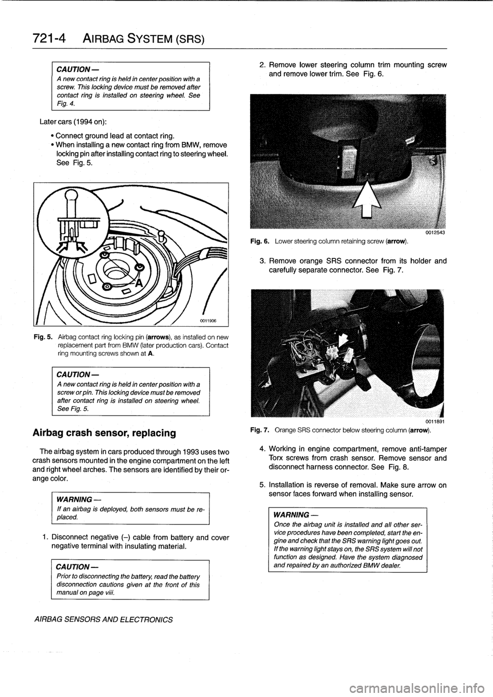
Fig
.
6
.
Lower
steering
column
retaining
screw
(arrow)
.
3
.
Remove
orange
SRS
connector
from
its
holder
and
carefully
separate
connector
.
See
Fig
.
7
.
Fig
.
7
.
Orange
SRS
connector
below
steering
column
(arrow)
.
4
.
Working
in
engine
compartment,
remove
anti-tamper
Torx
screwsfrom
crash
sensor
.
Remove
sensor
and
disconnect
harness
connector
.
See
Fig
.
8
.
5
.
Installation
is
reverse
of
removal
.
Make
sure
arrow
on
sensor
faces
forward
when
installing
sensor
.
WARNING
-
Once
the
airbag
unit
is
installed
and
all
other
ser-vice
procedures
have
been
completed,
start
the
en-
gine
and
check
that
the
SRS
warning
light
goes
out
.
If
the
warning
light
stays
on,the
SRS
system
will
not
function
as
designed
.
Have
the
system
diagnosed
and
repaired
byen
authorized
BMW
dealer
.
0012543
0011891
Page 481 of 759
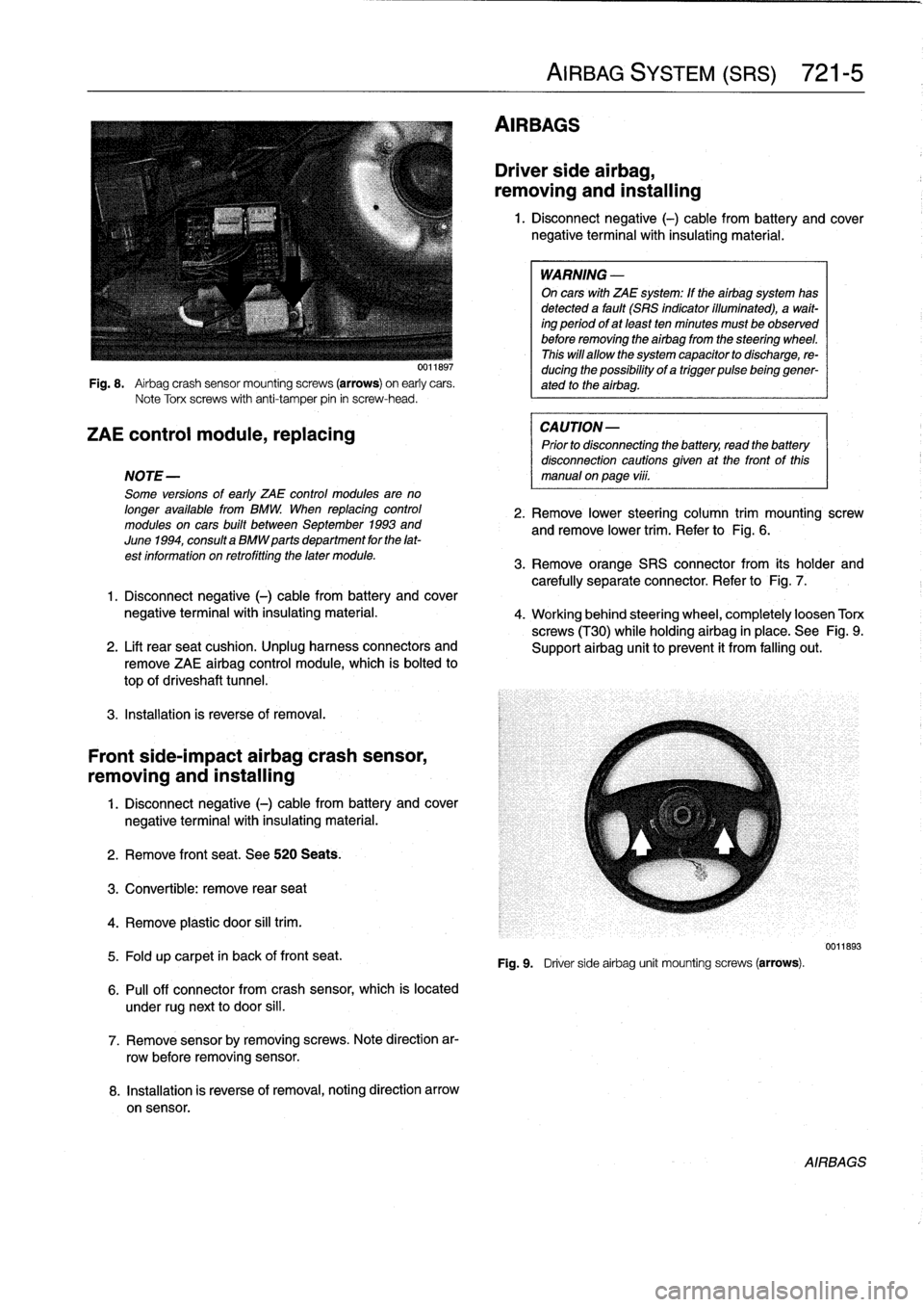
Fig
.
8
.
Airbag
crash
sensor
mountingscrews
(arrows)
on
early
cars
.
Note
Torx
screws
with
anti-tamper
pin
in
screw-head
.
ZAE
control
module,
replacing
NOTE-
Some
versions
of
early
ZAE
control
modules
are
no
longer
available
from
BMW
.
When
replacing
control
modules
on
cars
built
between
September
1993
and
June
1994,
consulta
BMW
parts
department
for
the
lat-
est
information
on
retrofitting
the
later
module
.
3
.
Remove
orange
SRS
connector
from
its
holder
and
carefully
separate
connector
.
Refer
to
Fig
.
7
.
1
.
Disconnect
negative
(-)
cable
from
battery
and
cover
negative
terminalwith
insulating
material
.
4
.
Working
behind
steering
wheel,
completely
loosen
Torx
screws
(T30)
while
holdingairbag
in
place
.
See
Fig
.
9
.
2
.
Lift
rearseat
cushion
.
Unplug
harness
connectors
and
Support
airbag
unit
toprevent
it
from
falling
out
.
remove
ZAE
airbag
control
module,
which
is
bolted
to
top
of
driveshaft
tunnel
.
3
.
Installation
is
reverse
of
removal
.
Front
side-impact
airbag
crash
sensor,
removing
and
installing
1
.
Disconnect
negative
(-)
cable
from
battery
and
cover
negative
terminal
with
insulating
material
.
2
.
Remove
front
seat
.
See520
Seats
.
3
.
Convertible
:
remove
rear
seat
4
.
Remove
plastic
door
sill
trim
.
5
.
Fold
up
carpet
in
back
of
front
seat
.
6
.
Pull
off
connector
from
crash
sensor,
which
is
located
under
rugnext
to
door
si¡¡
.
7
.
Remove
sensorby
removing
screws
.
Note
direction
ar-
row
before
removing
sensor
.
8
.
Installation
is
reverse
of
removal,noting
direction
arrow
on
sensor
.
AIRBAGS
AIRBAG
SYSTEM
(SRS)
721-
5
Driver
side
airbag,
removing
and
installing
1
.
Disconnect
negative
(-)
cable
from
battery
and
cover
negative
terminal
with
insulating
material
.
WARNING
-
On
cars
with
ZAE
system
:
If
theairbag
system
has
detected
a
fault
(SRS
indicator
illuminated),
a
wait-
ing
period
ofat
least
ten
minutes
must
be
observed
before
removing
the
airbag
from
the
steering
wheel
.
This
will
allow
the
system
capacitor
to
discharge,
re-
ducing
the
possibility
of
a
trigger
pulsebeinggener-
ated
to
the
airbag
.
CAUTION-
Prior
to
disconnecting
the
battery,
read
the
battery
disconnection
cautions
given
at
the
front
of
this
manual
on
page
vi¡¡
.
2
.
Remove
lower
steering
column
trim
mounting
screw
andremove
lower
trim
.
Refer
to
Fig
.
6
.
Fig
.
9
.
Driver
sideairbag
unit
mounting
screws
(arrows)
.
0011893
AIRBAGS
Page 482 of 759
721-
6
AIRBAG
SYSTEM
(SRS)
5
.
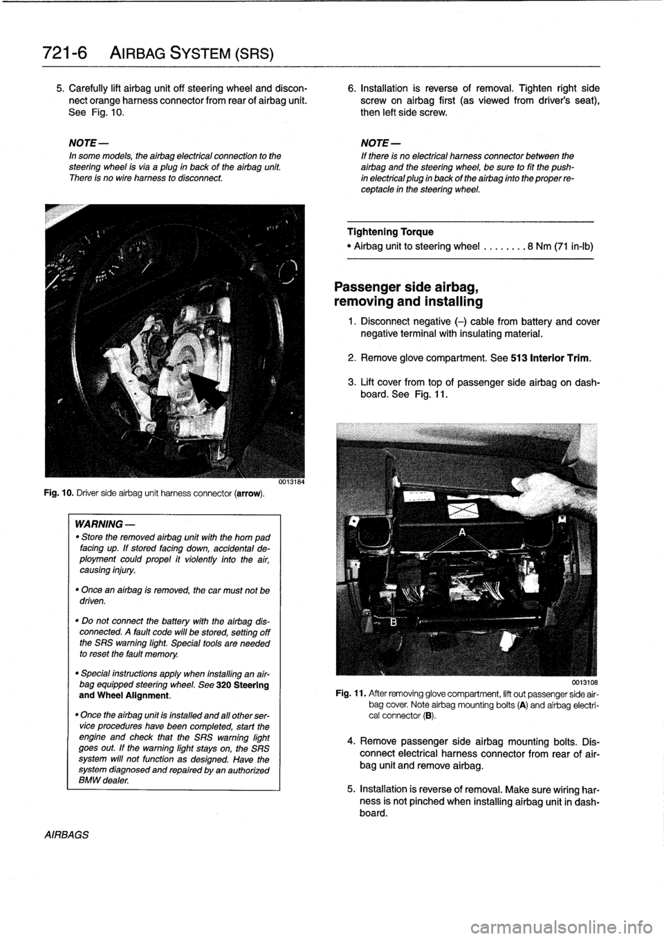
Carefully
lift
airbag
unit
off
steering
wheel
and
discon-
6
.
Installation
is
reverse
of
removal
.
Tighten
right
side
nect
orange
harness
connector
from
rear
of
airbag
unit
.
screw
on
airbag
first
(as
viewedfrom
driver's
seat),
See
Fig
.
10
.
then
left
side
screw
.
NOTE-
NOTE-
In
some
models,
theairbag
electrical
connection
to
the
If
there
is
no
electrical
harness
connector
between
the
steering
wheel
isvia
aplug
in
back
of
the
airbag
unit
.
airbag
and
the
steering
wheel,
be
sure
to
fit
the
push
There
is
no
wire
harness
to
disconnect
.
in
electrical
plug
in
back
of
the
airbag
finto
the
proper
re-
ceptacle
in
the
steering
wheel
.
Fig
.
10
.
Driver
sideairbag
unit
harness
connector
(arrow)
.
AIRBAGS
WARNING
-
"
Store
the
removed
airbag
unit
with
the
horn
pad
facing
up
.
If
stored
facing
down,
accidental
de-
ployment
couldpropel
it
violently
into
the
air,
causing
injury
.
"
Once
an
airbag
is
removed,
the
car
must
not
be
driven
.
"
Do
not
connect
the
battery
with
the
airbag
dis-
connected
.
A
fault
code
will
be
stored,
setting
off
the
SRS
warning
light
.
Special
tools
are
needed
to
reset
the
fault
memory
.
"
Special
instructions
apply
when
installing
an
air-
bag
equipped
steering
wheel
.
See
320
Steering
and
Wheel
Alignment
.
"
Once
the
airbag
unit
is
installnd
and
all
other
ser-vice
procedureshave
been
completed,
start
the
engíne
and
check
that
the
SRS
warning
light
goes
out
.
If
the
warning
light
stays
on,
the
SRS
system
will
not
function
as
designed
.
Have
the
system
diagnosed
and
repaired
by
an
authorized
BMW
dealer
.
0013184
Tightening
Torque
"
Airbag
unitto
steering
wheel
........
8
Nm
(71
in-lb)
Passenger
side
airbag,
removing
and
installing
1
.
Disconnect
negative
(-)
cable
from
battery
and
cover
negative
terminal
with
insulating
material
.
2
.
Remove
glove
compartment
.
See
513
Interior
Trim
.
3
.
Lift
cover
from
topof
passenger
sideairbag
on
dash-
board
.
See
Fig
.
11
.
0013108
Fig
.
11
.
After
removing
glove
compartment,
lift
out
passenger
side
air-
bag
cover
.
Note
airbag
mounting
bolts
(A)
and
airbag
electri-
cal
connector
(B)
.
4
.
Remove
passenger
sideairbag
mounting
bolts
.
Dis-
connect
electrical
harness
connector
from
rear
of
air-
bag
unit
and
remove
airbag
.
5
.
Installation
is
reverse
of
removal
.
Make
sure
wiring
har-
ness
is
not
pínched
when
installing
airbag
unit
in
dash-board
.
Page 751 of 759
2
INDEX
Brakes
(cont
.)
pressure
bleeding
brakes
(except
cars
wíth
AST)
340-3
troubleshooting
340-1
Brushes,
alternator
See
Battery,
starter,
alternator
Bulbs
See
Exterior
lighting
See
also
Instruments
Bumpers
See
Exterior
trim,
bumpers
C
CamberSee
Steering
and
wheel
alignment
Camshaft
See
Cylinder
head
and
valvetrain
Camshaft
position
sensor
See
Ignition
system
Camshaft
timing
chain
general
information
117-1
camshaft
timingchain,
4-cylinder
117-
2
camshaft
timing
chains,6-cylinder
117-6
camshaft
timing
chain,
removing
(4-cylinder
engines)
117-2
camshaft
timing
chains,
removing
(6-cylinder
engines)
117-7vanos
(variable
valve
timing)
117-14
control
unit,
removing
117-16system
operation,
testing
117-14
Caster
See
Steering
andwheel
alignment
Catalytic
convertor
See
Exhaustsystem
Cautions
viü
Center
bearing
See
Driveshaft
Center
console
See
interior
trim
Central
body
electronics
(ZKE
IV)
515-8
Central
locking
system
(ZVM)
515-7
Centrallocking
and
anti-theft
general
information
515-1
door
handles
and
Iocks
515-1
door
striker,
replacing
515-6
front
door
handle,
removing/
installing
515-3
front
door
lock,
removing/installing
515-1
rear
door
handle,
removing/installing
515-5
rear
door
lock,
removing/installing
515-4
EWS
II
control
module,
replacing
515-10
EWS
II
ring
antenna,
replacing
515-10
EWS
II
transmitter/receiver
module,
replacing
515-11
locking
system
and
electronic
immobilization
515-7
luggage
compartment
locking
actuator,
removing/installing
515-6
Clutch
general
information210-1
clutch
hydraulic
system,
bleeding
and
flushing
210-2
clutch,
inspecting
and
installing
210-5
clutch
master
cylinder,
replacing
210-2
clutch,
removing
210-4
clutch
slave
cylinder,
replacing
210-3
transmission
pilot
bearing,
replacing
210-6
Clutch
fluid
See
Maintenance
program
Coil
See
Ignition
system
Coilspring
See
Rear
suspension
Component
locations
See
Electrical
component
locations
Compressor
See
Air
conditioning
Compressor
clutch
See
Air
conditioning
Condenser
See
Air
conditioningControl
arms
See
Front
suspension
See
also
Rear
suspension
Convertible
top
general
information
541-1
manual
convertible
top
541-1
lid
release
mechanism
541-2
replacing
541-2
visor
latch
541-1
visor
latch
píate
541-1
power
convertible
top
541-2
drive
motor,
replacing
541-7
emergency
operation
541-7
front
latching
mechanism
541-4
lid
541-9
replacing
541-5
visor
latch
541-4
visor
latch
motor541-5
visor
latch
plate
541-4
rollover
protection
system
541-9
Coolant
(Anti-freeze)
See
Maintenance
program
Coolant
pump
See
Cooling
system
Cooling
system
general
information
170-1
cooling
fan,
replacing
170-8
coolant
pump,
replacing
170-10
coolant
pump
and
thermostat170-1
coolant,
draining/filling
170-5
cooling
fans
170-2
cooling
fan,
testing
170-4
cooling
system
service
170-5
cooling
system,
bleeding
(radiator
with
integral
expansion
tank)
170-6
cooling
system
pressure
test
170-3
electric
cooling
fan,
replacing
170-8
radiator,
removing/installing
170-11
Cooling
system
(cont
.)
radiator
and
expansion
tank
170-1
radiator
service
170-11
temperature
gauge
quick
check170-3
thermostat
quick
check
170-3
thermostat,
replacing
170-9
troubleshooting
170-2
warnings
and
cautions
170-2Crankshaft
position/rpm
sensor
See
Ignition
system
Crash
sensor
See
Airbag
system
(SRS)
CV
joint
See
Maintenance
program
See
also
Rear
suspension
Cylinder
head
and
valvetrain
general
information
116-1
camshaft116-7
camshafts,
removing/installing
(M42
engine)
116-1camshafts,
removing/installing
(M44
engine)
116-3
camshafts,
removing/installing
(6-cylinder
engine)
116-4
cylinder
head,
disassembly/assembly
116-1
cylinder
head
and
valvetrain,
reconditioning
116-7
cylinder
head
116-7
hydraulic
cam
followers,
checking
and
replacing
(M42
and
al]
6-cylinder
engines)
116-9
hydraulic
valve
adjusters,
checking
and
replacing
(M44
Engine)
116-8
valve
guides
116-10
valveseats
116-12
valve
springs
116-12
valve
stem
oil
seals
116-11
valves
116-11
valves,
leak
test
116-11
valves,removing/installing
116-6
Cylinder
head
removal
and
installation
general
information
113-1
cylinder
head,
removing/installing
(4-
cylinder
engine)
113-1
cylinder
head
(6-cylinder
engine),
removing/installing
113-10
Dashboard
See
Interior
trim
Deck
lid
See
Trunk
lid
Defogger
See
Heating
Differential
See
Final
drive
DISA
(dual
resonance
intake
system)
See
Fuel
injection
See
also
Engine-general
DME
(digital
motor
electronics)
See
Ignition
system
See
alsoFuel
injection
Page 755 of 759
6
INDEX
Ignition
system
general
information
120-1basictroubleshooting
principies
120-3camshaft
position
(CMP)
sensor
120-
6
camshaft
positíon
(CMP)
sensor,
replacing
(4-cylinder
engine)
120-6camshaft
position
(CMP)
sensor,
replacing
(6-cylinder
engines)
120-7
checking
for
spark
120-3
crankshaftposition/rpm
sensor
120-5
crankshaft
position/rpm
sensor,
testing/replacing
(front
mounted
sensor)
120-6
crankshaft
positíon/rpm
sensor,
testing
(rear
mounted
sensor)
120-6
disabling
ignition
system120-2
ignition
coil,
testing
and
replacing
(4-
cylinder
engines)
120-3
ignition
coil,
testing
and
replacing
(6-
cylinder
engines)
120-4
ignítion
firing
order
120-7
ignition
system
diagnostics
120-3
ignition
system
schematics
120-7
ignition
system
service
120-3knock
sensors,
replacing
120-7warnings
and
cautions
120-2
Inspectíon
I
and
Inspection
II
See
Maintenanceprogram
Instrumentpanel
See
interior
trim
Instruments
general
information
620-1
instrument
cluster,
removinglinstalling
620-1
instrument
cluster,
self-testing
620-1
instrument
cluster
bulbs,
replacing
620-2
multi-information
display
(MID),
620-4
multi-information
display
(MID),
removing/installing
620-4
odometer
coding
plug,
replacing
620-
2
vehicle
speed
sensor,
replacing
620-3
Intake
manifold
4-cylinder
engíne,
removing
113-3
6-cylinder
engine,
removing
113-11
See
alsoCylinder
head
removal
and
installation
Intake
air
temperaturesensor
See
Fuel
injection
Interior
trim
general
information
513-1
center
console,
removing/installing
513-1
dashboard,
removing/installing
513-3
glove
compartment,
removing/
installing
513-2
lower
left
dash
panel,
removing/
installing
513-2
J
Jump
startíng
010-12
K
Knock
sensor
See
Ignition
system
L
Leather
upholstery
See
Maíntenance
program
Leve¡
sender
See
Fuel
pump
Lubrication
system
general
information
119-1
oil
pan,
removing/installing
(4-cylinder
engines)
119-2
oil
pan,
removing/installing
(6-cylinder
engine,
1992models)119-4
oil
pan
119-2
oil
pan,
removing/installing
(6-cylinder
engine,
1993
and
later
models)
119-6
oil
pressure,
checking
119-1
oil
pressure
warningsystem,
testing
119-2
oil
pump
119-8
oil
pump,
removing/installing
(4-cylinder
engine)
119-8
oil
pump,
removing/installing
(6-cylinder
engine)
119-9
troubleshooting
119-1
M
Maíntenance
program
general
information
020-2
accelerator
and
throttle
linkage
020-13
air
filter,
replacing
020-11
automatic
transmission
fluid
020-8
automatic
transmission
service
020-18
battery,
checking
and
cleaning
020-12
battery,
replacing
020-12
BMW
service
indicator
020-2
body
and
hinges,
lubricating
020-19
brake
fluid
020-9
brake
fluid,
replacing
020-17
brake
pad/rotor
wear,
checking
020-17
brake
system,
inspecting
020-17
clutch
fluid,
checking
020-19
cooling
system
service
020-14
drive
axle
joint
boots,
inspecting
020-19
engine
coolant
(anti-freeze)
020-9
engine
drive
belts
020-13
engine
oil,
checking
leve¡
020-9
Maintenance
program
(cont
.)
engine
oil
and
filter,
changing020-9engine
oil
service
020-9
exhaust
system,
inspecting
020-18
exterior
washing020-20
final
drive
gear
oil
020-9
final
drive
oil
level,
checking
020-18
front
suspension
and
steering
linkages,
inspecting
020-18
fuel
filter,
replacing
020-16
fuel
tank
and
fuel
lines,
inspecting
020-19
¡dle
speed
020-12
inspection
I
and
inspection
11
020-2
interior
care020-20
leather
upholstery
and
trim
020-20
maintenance
tables
020-3
manual
transmission
fluid,
checking
and
filling
020-18manual
transmission
fluid
020-8
manual
transmission
service
020-18oxygensensors
020-15
parking
brake,
checking
020-17
polishing
020-20
poly-ribbed
belt,
replacing
020-13
power
steering
fluid
020-9
power
steering
fluid,
checking
leve¡
020-14
rear
suspension,
inspecting
020-18
resetting
service
indicator
020-3
seat
belts
020-20
spark
plugs,
replacing
020-11
special
cleaning
020-20
tires,
checking
inflation
pressure
020-17
tires,
rotating
020-17
v-belt,
replacing
020-13
washing
chassis
020-20waxing020-20
windshield
wiperblade
maintenance
020-19
wheels,
aligníng
020-17
Manual
transmission
See
also
Maintenance
program
See
also
Transmission-general
general
information
230-1
back-up
light
switch,
replacing
230-2
inputshaft
sea¡,
replacing
(transmission
installed)
230-5
output
shaftsea¡,
replacing
(transmission
installed)
230-4
selector
shaft
sea¡,
replacing
(transmission
installed)
230-3
transmission
fluid,
replacing
230-2
transmission
fluidlevel,
checking
230-2
transmission
fluid
service
230-1
transmission
removal
and
installation
230-5
transmission,
removing/installing
230-
6
transmission
service
230-2
Mass
air
flow
sensor
See
Fuel
Injection
Page 756 of 759
N
WARNING
Your
common
sense,
good
judge-
ment,
and
general
alertness
are
cru-
cial
to
safe
and
successful
service
work
.
Before
attempting
any
workonyour
BMW,
read
the
warnings
and
cautions
on
page
vi¡
and
the
copyright
page
at
the
front
of
the
manual
.
Review
these
warningsand
cautions
each
time
you
prepare
to
work
on
your
BMW
.
Please
also
read
any
warnings
and
cautions
that
accom-
pany
the
procedures
in
the
manual
.
Master
cylinder
See
Brakes
See
also
Clutch
Mechanical
troubleshooting
See
Engine-general
Microfilter
See
Air
conditioning
Mirror
See
Exterior
trim,
bumpers
Muffler
See
Exhaustsystem
Multi-information
display
(MID)
See
Instruments
Neutral
safetyswitch
See
Gearshift
linkage
O
Oil,
changing
See
Maintenance
program
Oil
panSee
Lubrication
system
Oil
pressure
See
Lubrication
system
Oil
pump
See
Lubrication
systemOn-board
diagnostics
(OBD)
See
Engine-general
See
alsoFuel
injection
See
also
Ignition
system
On-board
trip
computer
See
Multi-information
display
620-4
Oxygen
sensor
See
Engine-general
See
alsoFuel
injection
See
also
Maintenance
program
P
Parking
brake
See
Brakes
See
also
Maintenance
program
Parts
See
Fundamentals
for
the
do-it-
yourself
owner
Poly-ribbed
belt
See
Maintenance
program
Power
steering
See
Steering
and
wheel
alignment
Power
steering
(luid
See
Maintenance
program
R
Radiator
See
Cooling
system
Radio
general
information
650-1audio
system
650-1
radio
connector
650-6
removing/installing
650-2speakersdoor
panel
speaker,
removing/
installing
650-5
left
footwell
speaker,
removing/
installing
650-3
rear
speaker,
removing/installing
650-5
right
footwell
speaker,
removing/
installing
650-4Rearsuspension
See
also
Maintenance
program
general
information
330-1
coil
spring,
removing/installing
330-4
CV
boot,
replacing
330-8
drive
axle,
removing/installing
330-6
drive
axles
330-6
final
drive
carrier
330-12
final
drive
carrier,
removing/installing
330-12
lower
control
arm,
removing/installing
330-12
rear
shock
absorber,
removing/
installing
330-3
rear
suspension
arms
330-9
ride
heíght
330-1
shock
absorbers
and
springs
330-2
trailing
arm,
removing/installing
330-10
trailing
arm
bushing,
replacing
330-11upper
control
arm,
removing/installing
330-12
rear
wheel
bearing,
replacing
330-5
rear
wheel
bearings
330-4
Rear
view
mirror
See
Exterior
trim,
bumpers
Receiver/drivr
See
Air
conditioning
Relays
See
Electrical
component
locations
INDEX
7
Ride
height
See
Front
suspension
or
Rearsuspension
Ring
antenna
See
Central
locking
and
anti-theft
Roof
See
Convertible
top
See
also
Sunroof
Roundel
See
Exterior
trim,
bumpers
S
Seat
belts
general
information
720-1
automatic
front
seat
belt
lock
tensioners
720-2
center
rear
lap-belt,
removing/
installing
720-5
front
seat
beltreel,
removing/installing
720-3
mechanical
spring
tensioner,
disarming
720-2
rear
seat
belt,
removing/installing
(fixed
seat
back
models)
720-4
rear
seat
belt,
removing/installing
(fold-down
seat
back
models)
720-5Seats
general
information
520-1
front
seats520-1
manual
front
seat
assembly
520-3
power
front
seat
assembly
520-4
removing/installing
520-1
rear
seats
520-5
rear
seat
cushion
and
backrest,
removing/installing
(fixed
seat
backmodels)
520-5
rear
seat
cushion
and
backrest,
removing/installing
(fold-down
seat
back
models)520-5
rear
seat
backrest
side
section,
removing/installing
(fold-down
seat
back
models)520-6
Shiftinterlock
See
Gearshift
linkage
Shiftlever
See
Gearshift
linkage
Shíftlock
See
Gearshift
linkage
Shock
absorber
See
Front
suspension
See
also
Rear
suspension
Side-impact
airbag
See
Airbag
system
(SRS)
Slave
cylinder
See
Clutch
Service
indicator
See
Maintenanceprogram
Solenoid
See
Battery,
starter,
alternator
Spark
See
Ignition
system
Spark
plugs
See
Maintenance
program
Page 757 of 759
8
INDEX
Speakers
See
Radio
SRS
(Supplemental
restraint
system)
See
Airbag
system
(SRS)
Starter
See
Battery,
starter,
alternator
Steering
and
wheel
alignment
general
information
320-1
caster
and
camber
320-5
front
toe-in
and
toe
difference
angle
320-6
outer
tie
rod
end,
replacing
320-4
power
steering
pump,
removing/
installing
320-2
power
steering
system
320-2
power
steering
system,
bleeding/filling
320-3
rear
toe-in
320-6
steering
gear320-3
steering
gear
rack,
removing/installing
320-3
steering
wheel
320-1
steering
wheel,
removing/installing
320-1
tie
rod,
replacing
320-5
wheel
alignment
320-5
wheel
alignment
specifications
320-6
Steering
gear
See
steering
and
wheel
alignment
Strut
See
Front
suspension
Subframe
See
Front
suspension
Sunroof
general
information
540-1
motor,
removing/installing
540-3
panel,
adjusting
540-2
panel,
emergency
closing
540-2
Suspension,
front
See
Front
suspension
Suspension,
rear
See
Rear
suspension
Suspension,
steering
and
brakes
general
information
300-1
al¡
season
traction
(AST)
300-4
antilock
brake
system
(ABS)
300-2
brakes
300-2
front
suspension
300-1
integrated
systems
300-2
M3
suspension
and
brakes
300-7
steering
300-2
rear
suspension
300-2suspension
and
steering
troubleshooting
300-7
tires
and
wheels300-2
T
Switches
and
electrical
accessories
general
information
612-1
dome
light,
rear
map
lights,
trunk
light,
replacing
bulbs
612-7
hazard
warning
switch,
replacing
612-5
headlight
switch,
replacing
612-5
foglight
switch,
replacing
612-5
ignition
electrical
switch,
replacing
612-3
ignition
lock
cylinder,
replacing
612-4
ignition
switch
assembly
612-3
outside
mirror
switch,
replacing
612-6
power
window
switch,
replacing
612-5
turn
signal
switch
and
wiper
switch,
removing/installing
612-1
wiper
switch
See
turn
signal
and
wiper
switch
Taillight
See
Exterior
lighting
Thermostat
See
Cooling
system
Throttleposition
sensor
(TPS)
See
Fuel
injection
Throw-out
bearing
See
ClutchTierod
See
Steering
and
wheel
alignment
Tires
See
Suspension,
steering
and
brakes-general
See
also
Maintenance
program
Timing
chain
See
Camshaft
timing
chain
Toe-in
See
Steering
and
wheel
alignment
Tools
See
Fundamentals
for
the
do-it-
yourself
owner
Torque
convector
See
Automatic
transmission
Towing
See
Fundamentals
for
the
do-it-
yourself
owner
Traction
control
See
also
Suspension,
steering
and
brakes-general
Trailing
arm
See
Rear
suspension
Transmission-general
See
also
Automatic
transmission
See
also
Manual
transmission
general
information
200-1
automatic
transmission
200-1
manual
transmission
200-1
transmission
ID
codes
200-2
Transmission
fluid
See
Maintenance
program
See
also
Automatic
transmission
Transmission
input
shaft
See
Manual
transmission
Transmission
output
shaft
See
Manual
transmission
Trim,
interior
See
Interior
trim
Trunk
lid
general
information
412-1
trunk
lid,
412-1
trunk
lid,
aligning
412-1
trunk
lid,
removing/installing
412-1
trunk
lid
support
strut,
removing/
installing
412-2
U
Upholstery
See
Maintenance
program
U-joints
See
Driveshaft
V
V-belt
See
Maintenance
program
Vacuum
booster
See
Brakes
Vacuum
leaks
See
Engine-general
Valveguides
See
Cylinder
head
and
valvetrain
Valve
seals
See
Cylinder
head
and
valvetrain
Valveseats
See
Cylinder
head
and
valvetrain
Valves
See
Cylinder
head
and
valvetrain
Valvetrain
See
Cylinder
head
and
valvetrain
VANOS
(variable
valve
timing)
See
Camshaft
timing
chaín
See
also
Engine-general
Vehicle
identification
number
(VIN)
See
Fundamentals
for
the
do-it-
yourself
owner
Vehicle
speed
sensor
See
Instruments
Ventilation
See
Air
conditioning
See
also
Heating
Voltage
regulator
See
Battery,
starter,
alternator
Voltage
tests
See
Electrical
system-general
W
Warnings
vi¡
Washer
fluid
pump
See
Wipers
and
washers
Washers
See
Wipers
and
washers
Water
pump
See
Cooling
system
Waxing
See
Maintenance
program
Page 758 of 759
WARNING
Your
common
sense,
good
judge-
ment,
and
general
alertness
are
cru-
cial
to
safe
and
successful
service
work
.
Before
attempting
any
work
onyour
BMW,
read
the
warnings
and
cautions
on
page
vi¡
and
the
copyright
page
at
the
front
of
the
manual
.
Review
thesewarnings
and
cautions
each
time
you
prepare
to
work
onyour
BMW
.
Please
also
read
any
warnings
and
cautions
that
accom-
pany
the
procedures
in
the
manual
.
Wheel
bearings
See
Front
suspension
or
Rear
suspensionWheel,
steering
See
Steering
and
wheel
alignment
Wheels
See
Maintenance
program
Window
regulator
See
Door
windows
Window
switch
See
Switches
and
electrical
accessories
Windows,
door
See
Door
windows
Windshield
wipers
and
washers
See
Wipers
and
washers
See
also
Maintenance
program
Wiper
motor
See
Wipers
and
washers
Wipers
and
washers
general
information
611-1
washer
fluid
leve¡
sensor,
replacing
(models
with
check
control)
611-10
washer
(luid
pump,
replacing
611-9
washerfluid
reservoir,
replacing
611-9
windshield
spray
nozzle,
removing/
installing
611-9
windshield
wiper
assembly,removing/
installing
(4-door
models)611-3
windshield
wiper
assembly,removing/
installing
(2-door
models)611-5
wiperarms,
removing/installing
611-2
wiperblade
inserts,
replacing
611-2
wiper
blade
cleaning
problems
611-1wiper
blades,
replacing
611-1wiper
motor,
removing/installing
611-8
Wiring
diagrams
See
Electrical
wiring
diagrams
Z
INDEX
9
ZAE
See
Airbag
system
(SRS)
ZKE
See
Central
body
electronics
ZVM
See
Central
locking