torque BMW M3 1998 E36 Manual Online
[x] Cancel search | Manufacturer: BMW, Model Year: 1998, Model line: M3, Model: BMW M3 1998 E36Pages: 759
Page 231 of 759
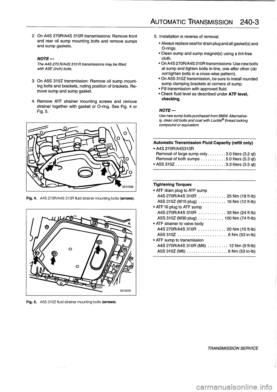
2
.
On
MS
270R/A4S
310R
transmissions
:
Remove
front
5
.
Installation
is
reverse
of
Rmoval
.
and
rear
oil
sump
mounting
bolts
andremove
sumps
"
Always
replace
sea¡
for
drain
plug
and
al¡
gasket(s)
andand
sump
gaskets
.
O-rings
.
"
Clean
sump
and
sump
magnet(s)
using
a
lint-free
NOTE-
cloth
.
The
MS
270
R/A4S
310
R
transmissions
may
be
fitted
"
On
MS
270R/A4S310R
transmissions
:
Use
new
bolts
with
ASE
(inch)
bolts
.
at
sump
and
tighten
bolts
in-line,
one
after
other
(do
nottighten
bolts
in
a
cross-wise
pattern)
.
3
.
On
A5S
310Z
transmission
:
Remove
oil
sump
mount-
"
On
MS
310Z
transmission,
be
sureto
instan
rounded
ing
bolts
and
brackets,
noting
position
of
brackets
.
Re-
sump
clamping
brackets
at
corners
of
sump
.
move
"
Fill
transmission
with
approved
fluid
.
sump
and
sump
gasket
.
"
Check
fluid
level
as
described
under
ATF
leve¡,
4
.
Remove
ATF
otra¡ner
mount¡ng
screws
and
remove
checking
.
strainer
together
with
gasket
orO-ring
.
See
Fig
.
4
or
Fig
.
5
.
Fig
.
4
.
A4S
270R/A4S310R
fluid
strainer
mounting
boits
(arrows)
.
Fig
.
5
.
A5S
310Z
fluid
strainer
mounting
boits
(arrows)
.
0013230
AUTOMATIC
TRANSMISSION
240-
3
NOTE-
Use
newsump
bolts
purchased
from
BMW
.
Alternative-
ly,
clean
old
bolts
and
coat
with
Loctite®
thread
locking
compound
or
equivalent
Automatic
Transmission
Fluid
Capacity
(refill
only)
"
MS
270R/A4S310R
Removal
of
large
sump
only
........
3
.0liters
(3.2
qt)
Removal
ofboth
sumps
...........
5
.0liters(5
.3
qt)
"
MS
310Z
..
..
..................
3
.3liters
(3.5
qt)
Tightening
Torques
"
ATF
drain
plug
to
ATF
sump
MS
270R/A4S
310R
..........
..
25
Nm
(18
ft-Ib)
MS
310Z(M10
plug)
..........
..
16
Nm
(12
ft-Ib)
"
ATF
fill
plug
to
ATF
sump
MS
270R/A4S
310R
..........
..
33
Nm
(24
ft-Ib)
MS
310Z(M30
plug)
.....
..
..
:.
100
Nm
(74
ft-Ib)
"
ATF
strainer
to
valve
body
MS
270R/A4S
310R
.....
..
.
...
.
20
Nm
(15
ft-Ib)
MS
310Z
..............
..
.
...
..
6
Nm
(53
in-lb)
"
ATF
sump
to
transmission
MS
270R/A4S
310R
(M6)
.
..
.
..
...
12
Nm
(9
ft-¡b)
MS
310Z
(M6)
..........
..
.
..
...
6
Nm
(53
in-¡b)
TRANSMISSION
SERVICE
Page 233 of 759
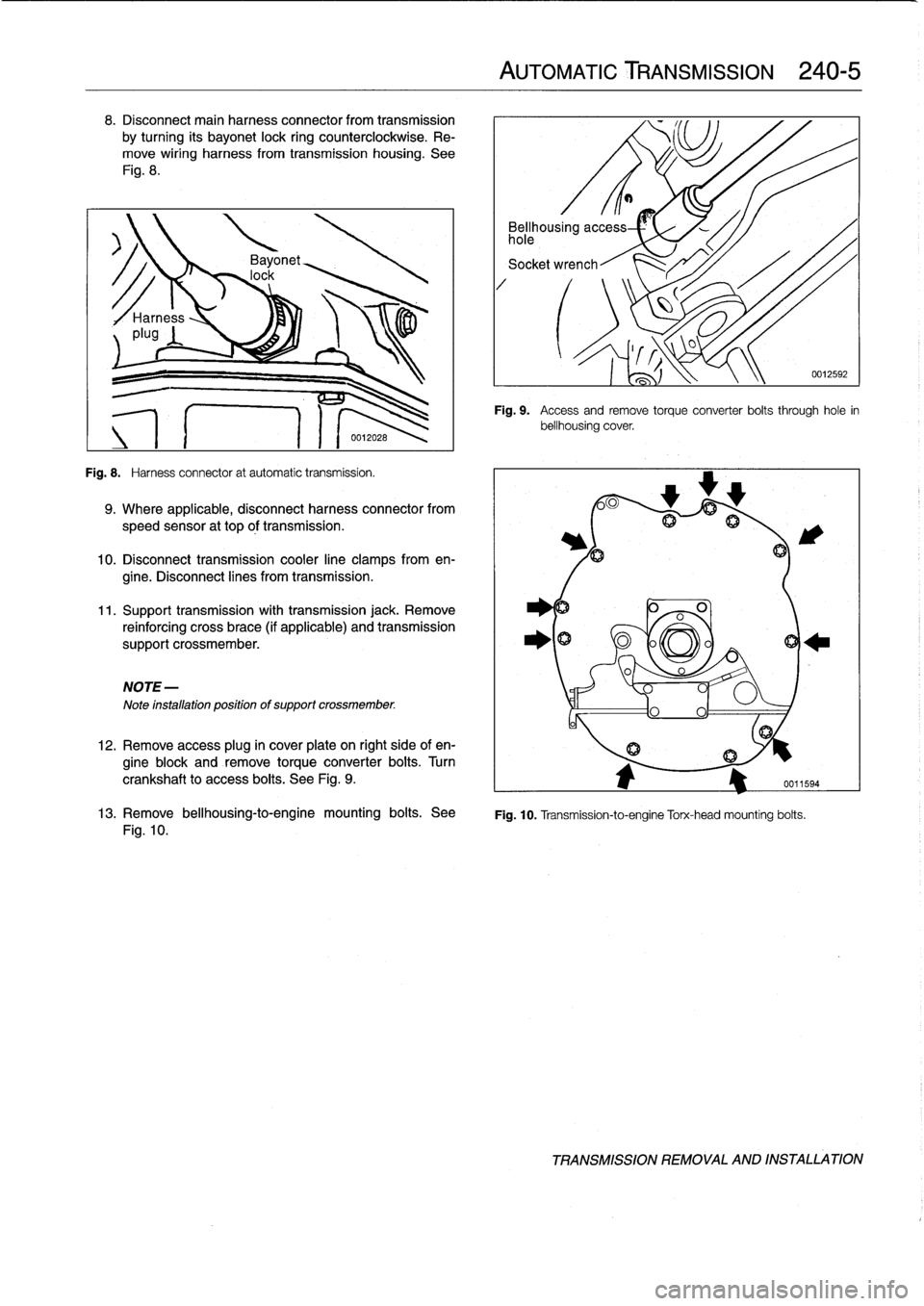
8
.
Disconnect
main
harness
connector
from
transmission
by
turning
its
bayonet
lock
ring
counterclockwise
.
Re-
move
wiring
harness
from
transmission
housing
.
See
Fig
.
8
.
Fig
.
8
.
Harness
connector
at
automatic
transmission
.
9
.
Where
applicable,
disconnect
harness
connector
from
speed
sensor
at
top
óf
transmission
.
10
.
Disconnect
transmission
cooler
line
clamps
from
en-
gine
.
Disconnect
lines
from
transmission
.
11
.
Support
transmission
with
transmission
jack
.
Remove
reinforcing
cross
brace
(if
applicable)
and
transmission
support
crossmember
.
NOTE-
Note
installation
positionof
support
crossmember
.
12
.
Remove
access
plug
in
cover
plate
on
right
side
of
en-
gine
block
and
remove
torqueconverter
bolts
.
Turn
crankshaft
to
access
boits
.
See
Fig
.
9
.
AUTOMATIC
TRANSMISSION
240-
5
Bellhousing
access
hole
Socket
wrench
Fig
.
9
.
Access
andremove
torque
converter
boits
through
hole
in
bellhousing
cover
.
0
A
fij
13
.
Remove
bellhousing-to-engine
mounting
bolts
.
See
Fig
.
10
.
Transmission-to-engine
Torx-head
mounting
bolts
.
Fig
.
10
.
0012592
TRANSMISSION
REMOVAL
AND
INSTALLATION
Page 234 of 759
240-
6
AUTOMATIC
TRANSMISSION
14
.
Remove
transmission
by
pulling
back
and
down
.
Lower
jack
to
allow
transmission
to
clear
vehicle
.
Tightening
Torques
"
ATF
drain
plug
to
ATF
sump
CA
UTION-
MS
270R/A4S
310R
....
..
....
.
..
25
Nm
(18
ft-Ib)
Do
not
allow
the
torque
converter
to
fati
off
the
ASS
310Z(M10
plug)
..
..
..
.
.
..
.
..
16
Nm
(12
ft-Ib)
transmission
inputshaft
.
"
ATF
fill
plug
to
ATF
sump
MS
270R/A4S
310R
..
..
....
..
..
.
33
Nm
(24
ft-Ib)
15
.
Installation
is
reverse
of
removal,
noting
the
following
:
MS
310Z(M30
plug)
......
.
.
..
.
.
100
Nm
(74
ft-Ib)
"Blowoutofcoolerlineswithlow-pressurecompressed
"
ATF
cooler
lines
(A4S
270R/A4S
310R)
air
and
flush
coolerwith
clean
ATF
twice
before
reat-
Coupling
nuts
............
.
.
..
..
.
20
Nm
(15
ft-Ib)
taching
lines
to
transmission
.
Hollow
bolts
.........
.
.....
..
..
.
37
Nm
(28
ft-Ib)
"
Reinforcing
cross
brace
CAUTION-
to
chassis
(M10)
.............
.
..
.
42
Nm
(31
ft-Ib)
"
Wear
safety
glasses
when
working
with
com-
"
Torque
converter
pressedair
.
to
driveplate
(M10)
.........
..
.
..
45
Nm
(33
ft-Ib)
"
Transmissionsupport
crossmember
to
chassis
"
Do
not
reuse
ATF
after
flushing
.
M8
......................
22-24
Nm
(16-17
ft-1b)
M10
................
.
....
..
.
..
42
Nm
(31
ft-Ib)
"
Install
new
sealing
washers
on
hollow
bolts
.
"
Transmissíon
to
engine
(Torx-head
with
washer)
"
Insta¡¡
new
O-rings
on
transmission
cooler
lines,
where
M8
......................
..
.
..
21
Nm
(15
ft-Ib)
applicable
.
M10
.....................
..
..
.
42
Nm
(31
ft-Ib)
"
Inspect
driveplate
for
cracks
or
elongatedholes
.
Re-
M12
................
.
....
..
.
..
72
Nm
(53ft-Ib)
place
if
necessary
.
"
Check
to
be
sure
torque
converter
is
seated
correctly
in
transmission
during
final
installation
.
"
When
mounting
transmission
to
engine,
the
three
mounting
tabs
on
torque
converter
must
be
aligned
with
indentations
on
driveplate
.
Use
an
alignment
dowel
to
line
up
bolt
holes,
if
necessary
.
"
Fill
transmission
with
clean
ATF
until
oil
leve¡
is
even
with
fill
hole
.
Then
check
fluid
leve¡
as
described
ear-
lier
.
"
Adjust
gearshift
mechanism
.
See
250
Gearshift
link-
age
.
NOTE-
Torx-head
mounting
bolts
shouldalwaysbe
used
with
washers
to
prevent
difficult
removal
.
TRANSMISSION
REMOVAL
AND
INSTALLATION
Page 237 of 759
2
.
Install
rubber
grommet
with
arrow
pointing
forward
.
In-
AUTOMATic
TRANSMISSION
stall
shift
rod
and
shift
boot
.
GEARSHIFT
NOTE-
Install
rubbergrommet
correctly
so
that
is
seals
outwa-
ter
.
4
.
Install
driveshaft
and
heat
shield
.
See
260
Driveshaft
.
Manual
valveleven
(at
transmission)
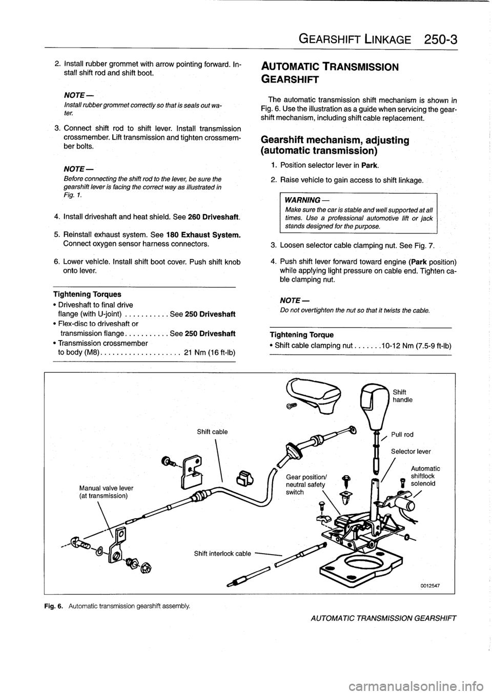
Fig
.
6
.
Automatic
transmission
gearshift
assembfy
.
Shift
cable
GEARSHIFT
LINKAGE
250-
3
The
automatic
transmission
shift
mechanism
is
shown
in
Fig
.
6
.
Use
the
illustration
as
a
guide
when
servícing
the
gear-
shift
mechanism,
including
shift
cable
replacement
.
3
.
Connect
shift
rod
to
shift
lever
.
Install
transmission
crossmember
.
Lift
transmission
and
tighten
crossmem-
Gearshift
mechanism,
adjusting
ber
bolts
.
(automatictransmission)
NOTE-
1
.
Position
selector
lever
in
Park
.
Beforeconnecting
the
shift
rod
to
the
lever,
be
sure
the
2
.
Raise
vehicle
to
gain
access
to
shift
linkage
.
gearshift
leven
is
facing
the
correct
way
as
illustrated
in
Fig
.
1
.
WARNING
-
Make
sure
thecan
is
stable
and
well
supported
at
all
times
.
Use
a
professional
automotive
lift
or
jack
stands
designed
for
the
purpose
.
5
.
Reinstall
exhaust
system
.
See
180
Exhaust
System
.
Connect
oxygen
sensor
harness
connectors
.
3
.
Loosen
selector
cable
clamping
nut
.
See
Fig
.
7
.
6
.
Lower
vehicle
.
Insta¡¡
shift
boot
cover
.
Push
shift
knob
4
.
Push
shift
lever
forwardtoward
engine(Park
position)
onto
lever
.
while
applying
light
pressure
on
cable
end
.
Tighten
ca-
ble
clamping
nut
.
Tightening
Torques
NOTE-
"
Driveshaft
to
final
drive
Do
not
overtighten
the
nut
so
that
it
twists
the
cable
.
flange
(with
U-joint)
.
..
.
.....
.
.
See
250
Driveshaft
"
Flex-disc
to
driveshaft
or
transmission
flange
...
.
.......
See
250
Driveshaft
Tightening
Torque
"
Transmission
crossmember
"
Shift
cable
clamping
nut
.......
10-12
Nm
(75-9
ft-Ib)
to
body
(M8)
.
.
.
...
..............
21
Nm
(16
ft-Ib)
/S
r\
1
1
Gear
position/
neutral
safetyswitch
Automatic
shilo
solenoid
id
AUTOMATIC
TRANSMISSION
GEARSHIFT
Page 238 of 759
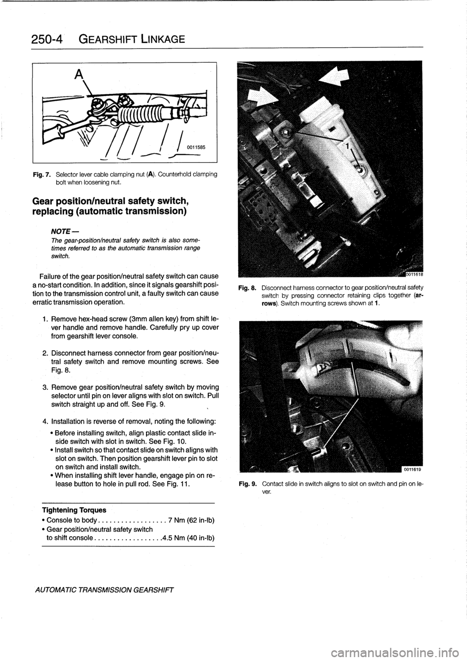
250-
4
GEARSHIFT
LINKAGE
r%
;
5
(((((C
"
~
;
Fig
.
7
.
Selector
lever
cable
clamping
nut
(A)
.
Counterhold
clamping
bolt
when
loosening
nut
.
Gear
position/neutral
safety
switch,
replacing
(automatic
transmission)
NOTE-
The
gear-positionlneutral
safetyswitch
is
also
some-
times
referred
to
as
the
automatic
transmission
range
switch
.
Failure
of
the
gear
positionlneutral
safetyswitch
can
cause
a
no-start
condition
.
In
acidition,
since
it
signals
gearshift
posi-
tion
tothe
transmission
control
unit,
a
faulty
switch
can
cause
erratic
transmission
operation
.
1
.
Remove
hex-head
screw
(3mm
allen
key)
from
shift
le-
ver
handle
and
remove
handle
.
Carefully
pry
up
cover
from
gearshift
lever
console
.
2
.
Disconnect
harness
connector
from
gear
positionlneu-
tral
safety
switch
andremove
mounting
screws
.
See
Fig
.
8
.
3
.
Remove
gear
positionlneutral
safety
switch
by
moving
selector
until
pin
on
lever
aligns
with
slot
on
switch
.
Pull
switch
straight
up
and
off
.
See
Fig
.
9
.
4
.
Installation
is
reverse
of
removal,
noting
the
following
:
"
Before
installing
switch,
align
plastic
contact
slide
in-
sideswitch
with
slot
in
switch
.
See
Fig
.
10
.
"
Instan
switch
so
that
contact
slide
on
switch
aligns
with
slot
on
switch
.
Then
position
gearshift
lever
pin
to
slot
on
switch
and
install
switch
.
"
When
installing
shift
lever
handle,
engage
pín
on
re
leasebutton
to
hole
in
pulí
rod
.
See
Fig
.
11
.
Fig
.
9
.
Contact
slide
in
switch
aligns
toslot
on
switch
and
pin
on
le-
ver
.
Tightening
Torques
"
Console
to
body
..............
...
.
7
Nm
(62
in-lb)
"
Gear
positionlneutral
safety
switch
to
shift
console
.................
.
4
.5
Nm
(40
in-lb)
AUTOMATIC
TRANSMISSION
GEARSHIFT
Fig
.
8
.
Disconnect
harness
connector
to
gear
position/neutral
safety
switch
by
pressing
connector
retaining
clips
together
(ar-
rows)
.
Switch
mountingscrews
shown
at
1
.
Page 241 of 759
DRIVESHAFT
SERVICE
.
...
.
.
.
...
.
..
.
.
.260-3
Driveshaft,
aligning
...............
.
...
.
.
260-3
Driveshaft,
removing
..............
.
.
.
.
.
.
260-4
260
Driveshaft
DRIVESHAFT
260-1
GENERAL
.
.
.
.
.
.
.
.....
.
.
.
........
.
...
.
260-1
Driveshaft,
installing
.
....
.
..
.
............
260-4
Flex-disc,
replacing
.....
.
.
.
.............
260-5
TROUBLESHOOTING
..
.
.
.
...
.
.........
260-1
Center
bearing
assembly,
replacing
.
......
.260-6
Frontcentering
guide,
replacing
..
.
.......
.
260-7
TABLE
a
.
Driveshaft
Troubleshooting
.
.
...
......
.
....
..
.
.
260-2
GENERAL
NOTE-
For
rear
drive
axlerepair
information,
see330
Rear
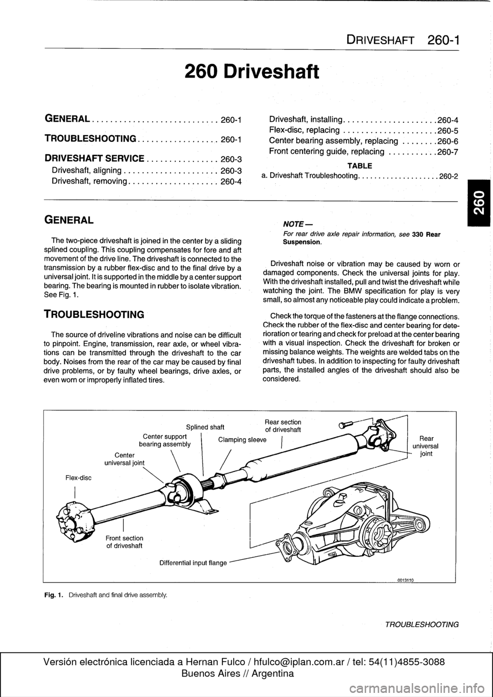
The
two-piece
driveshaft
is
joined
in
thecenter
by
a
sliding
Suspension
.
splined
coupling
.
This
coupling
compensates
for
fore
and
aft
movement
of
the
drive
line
.
The
driveshaft
ís
connected
to
the
Driveshaft
noise
or
vibration
may
be
caused
by
worn
or
transmission
bya
rubber
flex-disc
and
to
the
final
drive
by
a
damaged
components
.
Check
the
universal
joints
for
play
.
universal
joint
.
It
is
supported
in
the
micidle
by
a
center
support
With
the
driveshaft
installed,
pull
and
twist
the
driveshaft
while
bearing
.
The
bearing
is
mounted
in
rubber
to
isolate
vibration
.
watching
the
joint
.
The
BMW
specificationfor
play
is
very
See
Fig
.
1
.
small,
so
almost
any
noticeableplay
could
indicate
a
problem
.
TROU
BLESHOOTING
Check
thetorque
of
thefasteners
at
the
flange
connections
.
Check
therubber
of
the
flex-disc
and
center
bearing
for
dete
The
source
of
driveline
vibrations
and
noise
can
be
difficult
rioration
or
tearíng
and
check
for
preload
at
the
center
bearing
to
pinpoint
.
Engine,
transmission,
rear
axle,
or
wheel
vibra-
with
a
visual
inspection
.
Check
the
driveshaft
for
broken
or
tions
can
be
transmitted
through
the
driveshaft
to
the
car
missing
balance
weights
.
The
weights
are
welded
tabs
on
the
body
.
Noises
from
the
rear
of
thecar
may
be
caused
by
final
driveshaft
tubes
.
In
addition
to
inspecting
for
faulty
driveshaft
drive
problems,
orby
faulty
wheel
bearings,
drive
axies,
or
parts,
the
installed
angles
of
the
driveshaft
should
also
be
evenworn
or
improperly
inflatedtires
.
considered
.
Flex-disc
Center
universal
joint
Fig
.1
.
Driveshaft
and
final
drive
assembly
.
Rear
section
Splined
shaft
of
driveshaft
Center
support
`
Clamping
sleeve
bearíng
assembly
Differential
inputflange
0013110
TROUBLESHOOTING
Page 245 of 759
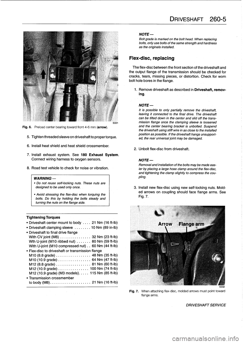
Fig
.
6
.
Preload
center
bearing
toward
front
4-6
mm
(arrow)
.
5331
5
.
Tightenthreadedsleeveondriveshafttopropertorque
.
6
.
Insta¡¡
heat
shield
and
heat
shield
crossmember
.
Tightening
Torques
"
Driveshaftcenter
mount
to
body
.
.
..
21
Nm
(16
ft-Ib)
"
Driveshaft
clamping
sleeve
.....
.
.
.
10
Nm
(89
in-lb)
"
Driveshaft
to
final
drive
flange
With
CV
joint
(M8)
............
...
32
Nm
(23
ft-Ib)
Wth
U-joint
(M10
ribbed
nut)
....
...
80
Nm
(59
ft-Ib)
With
U-joint
(M10
compressed
nut)
..
60
Nm
(44
ft-Ib)
"
Flex-disc
to
driveshaft
or
transmissionflange
M10
(8.8
grade)
.........
.
....
..
.
48
Nm
(35
ft-Ib)
M10
(10
.9
grade)
........
.
....
...
64
Nm
(47
ft-Ib)
M12
(8.8
grade)
........
.....
..
.
.
81
Nm
(60
ft-Ib)
M12
(10
.9
grade)
.
.
....
......
...
100
Nm
(74
ft-Ib)
M12
(10
.9
grade)
(M3
models)
..
.
.
.
115
Nm
(85
ft-Ib)
"
Transmission
crossmember
to
body
(M8)
.
....
...........
....
21
Nm
(16
ft-Ib)
NOTE-
Bolt
grade
is
markedon
the
bolt
head
.
When
replacing
bolts,
only
use
bolts
of
the
same
strength
and
hardnessas
the
originalsinstalled
.
Flex-disc,
replacing
The
flex-disc
between
the
front
section
of
the
driveshaft
and
theoutputflange
of
the
transmission
should
be
checked
for
cracks,
tears,
missing
pieces,
or
distortion
.
Check
for
worn
bolt
hole
bores
in
theflange
.
1
.
Remove
driveshaft
as
described
in
Driveshaft,
remov-
ing
.
NOTE-
¡t
is
possible
to
only
partially
remove
the
driveshaft,
leaving
it
connected
to
the
final
drive
.
The
driveshaft
canbe
tilted
down
in
thecenter
and
slidoff
the
trans-
mission
flange
once
the
clamping
sleeve
is
loosened
and
the
center
bearing
bracket
is
unbolted
.
Suspend
the
driveshaft
using
stiff
wire
in
as
close
to
the
installed
position
as
possible
.
If
the
driveshaft
hangs
unsupport-
ed,
the
rear
universal
joint
may
be
damaged
.
2
.
Unbolt
flex-dísc
from
driveshaft
.
DRIVESHAFT
260-
5
7
.
Install
exhaust
system
.
See
180
Exhaust
System
.
Connect
wiring
harness
to
oxygen
sensors
.
NOTE-
Removaland
installation
of
the
boltsmaybe
made
eas-
8
.
Road
test
vehicle
to
check
for
noiseor
vibration
.
ier
by
placing
a
large
hose
clamp
around
the
flex-disc,
and
tightening
the
clamp
slightlyto
compress
the
cou
WARNING
-
pling
.
"
Do
not
reuse
self-locking
nuts
.
These
nuts
aredesigned
to
beused
only
once
.
3
.
Insta¡¡
new
flex-disc
using
new
self-locking
nuts
.
Mold-
"
Avóid
stressing
the
flex-disc
when
torquing
the
ed
arrows
on
coupling
should
face
flange
arms
.
See
bolts
Do
this
holding
the
bolts
Fig
.
7
.
steady
and
.
uy
turning
the
nuts
on
theflange
side
.
5
:132
Fig
.
7
.
When
attaching
flex-disc,
molded
arrows
must
point
toward
flange
arms
.
DRIVESHAFT
SERVICE
Page 246 of 759
260-
6
DRIVESHAFT
4
.
Insta¡¡
driveshaft
as
described
in
Driveshaft,
install-
ing
.
Tightening
Torques
"
Driveshaft
center
mount
to
body
.
...
21
Nm
(16
ft-Ib)
"
Driveshaft
clamping
sleeve
.....
...
10
Nm
(89
in-lb)
"
Driveshaft
to
final
drive
flange
With
CV
joint
(M8)
............
...
32
Nm
(23
ft-Ib)
Wth
U-joint
(M10
ribbed
nut)
......
.
80
Nm
(59
ft-Ib)
With
U-joint
(M10
compressed
nut)
.
.
60
Nm
(44
ft-Ib)
"
Flex-disc
to
driveshaft
or
transmission
flange
M10
(8
.8
grade)
.
...
.............
48
Nm
(35
ft-Ib)
M10
(10
.9
grade
.
...
.............
64
Nm
(47
ft-Ib)
M12
(8
.8
grade)
..
..
.............
81
Nm
(60
ft-Ib)
M12
(10
.9
grade)
.
..
............
100
Nm
(74
ft-Ib)
M12
(10
.9
grade)
(M3
models)
.....
115
Nm
(85
ft-Ib)
"
Transmission
crossmember
to
body
(M8)
......
...
.
..
........
21
Nm
(16
ft-Ib)
5
.
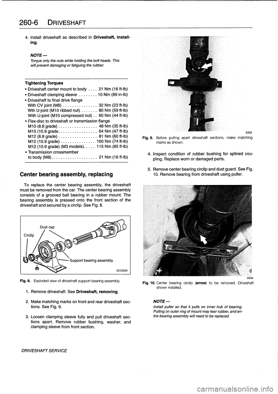
Remove
center
bearing
circlip
and
dust
guard
.
See
Fig
.
Center
bearing
assembly,
replacing
10
.
Remove
bearing
from
driveshaft
using
puller
.
To
replace
thecenter
bearing
assembly,
the
driveshaft
must
be
removed
from
thecar
.
The
center
bearing
assembly
consists
of
a
grooved
ball
bearing
in
a
rubber
mount
.
The
bearing
assembly
is
pressed
onto
the
front
section
of
the
driveshaft
and
securedby
a
circlip
.
See
Fig
.
8
.
Circlip
NOTE
-
Torque
only
the
nuts
while
holding
the
bolt
heads
.
Thís
will
prevent
damaging
or
fatiguing
the
rubber
.
Dust
cap
Fig
.
8
.
Exploded
view
of
driveshaft
support
bearing
assembly
.
1
.
Remove
driveshaft
.
See
Driveshaft,
removing
.
DRIVESHAFT
SERVICE
0012594
5333
Fig
.
9
.
Before
pulling
apart
driveshaft
sections,
make
matching
marks
as
shown
.
4
.
Inspect
condition
of
rubber
bushing
for
splined
cou-
pling
.
Replace
worn
or
damaged
parts
.
2
.
Make
matching
marks
on
front
and
rear
driveshaft
sec-
NOTE-
tions
.
See
Fig
.
9
.
Install
puller
so
that
it
pulls
on
inner
hub
of
bearing
.
Pulling
on
outer
ring
of
mount
may
tear
rubber,
and
en
3
.
Loosen
clamping
sleeve
fully
and
pull
driveshaft
sec-
tire
bearing
assembly
will
need
to
be
replaced
.
tions
apart
.
Remove
rubber
bushing,
washer,
and
clamping
sleeve
from
front
section
.
5334
Fig
.
10
.
Center
bearing
circlip
(arrow)
to
be
removed
.
Driveshafl
shown
installed
.
Page 247 of 759
6
.
Before
installation,
make
sure
dust
guard
is
on
drive-
2
.
Pack
cavity
behind
centering
guide
with
heavy
grease
shaft,
and
then
press
center
mount
onto
driveshaft
until
grease
is
flush
with
bottom
edge
of
guide
.
flush
with
dust
guard
.
3
.
Insert
14
mm
(approximately
%z
in
.)
diameter
mandrel
7
.
Place
clamping
sleeve,
washer,
and
rubber
bushing
on
or
metal
rod
finto
guide
.
Strike
guide
with
hammer
to
front
driveshaft
section
.
Lubricate
splines
with
molyb-
force
centering
guide
out
.
denum
disulfide
grease
(Molykote
0
Longterm
2
or
equivalent)
and
then
reassemble
driveshaft
.
NOTE-
The
mandrel
should
fit
snugly
in
thecentering
guideso
NOTE-
that
the
greasecannot
escapearound
the
sides
of
the
Do
not
retighten
clamping
sleeve
until
driveshaft
is
in-
mandrel
.
stalled
.
4
.
Remove
old
greasefrom
driveshaft,
lubricate
new
cen
8
.
Insta¡¡
dríveshaft
.
See
Driveshaft,
installing
.
tering
guide
with
molybdenum
disulfide
grease
(Molykote
®
Longterm2
or
equivalent)
and
drive
it
finto
9
.
Tighten
clamping
sleeve
.
driveshaft
.
NOTE-
Tightening
Torque
The
sealing
lip
of
the
guide
should
face
outward
and
it
"
Clamping
sleeve
.....
...
.
..
......
10
Nm
(7
.5
ft-Ib)
shouldbe
driven
into
the
driveshaft
to
a
specified
depth
.
See
Fig
.
11
.
Front
centering
guide,
replacing
The
front
centering
guide
centers
the
driveshaft
in
relation
to
the
transmission
.
The
guide
is
press-fit
finto
a
cavity
in
the
frontof
the
driveshaft
and
slides
onto
the
transmission
output
shaft
.
No
specifications
are
given
for
wear
of
the
guide,
but
gener-
ally
theguide
should
fit
snugly
on
thetransmissionoutput
shaft
.
NOTE-
Some
driveshafts
have
a
dust
cap
installed
on
the
end
of
the
driveshaft,
over
thecentering
guide
.
The
dust
cap
may
become
bent
or
distorted
when
the
driveshaft
is
removed
or
installed
.
Damage
to
the
dust
capshould
not
affect
the
centering
guide
and
should
not
be
mistak-
en
for
guide
wear
.
1
.
Remove
driveshaft
.
See
Driveshaft,
removing
.
®RIVESHAFT
260-
7
~)I~
4
.5
mm
(
.177")
B313
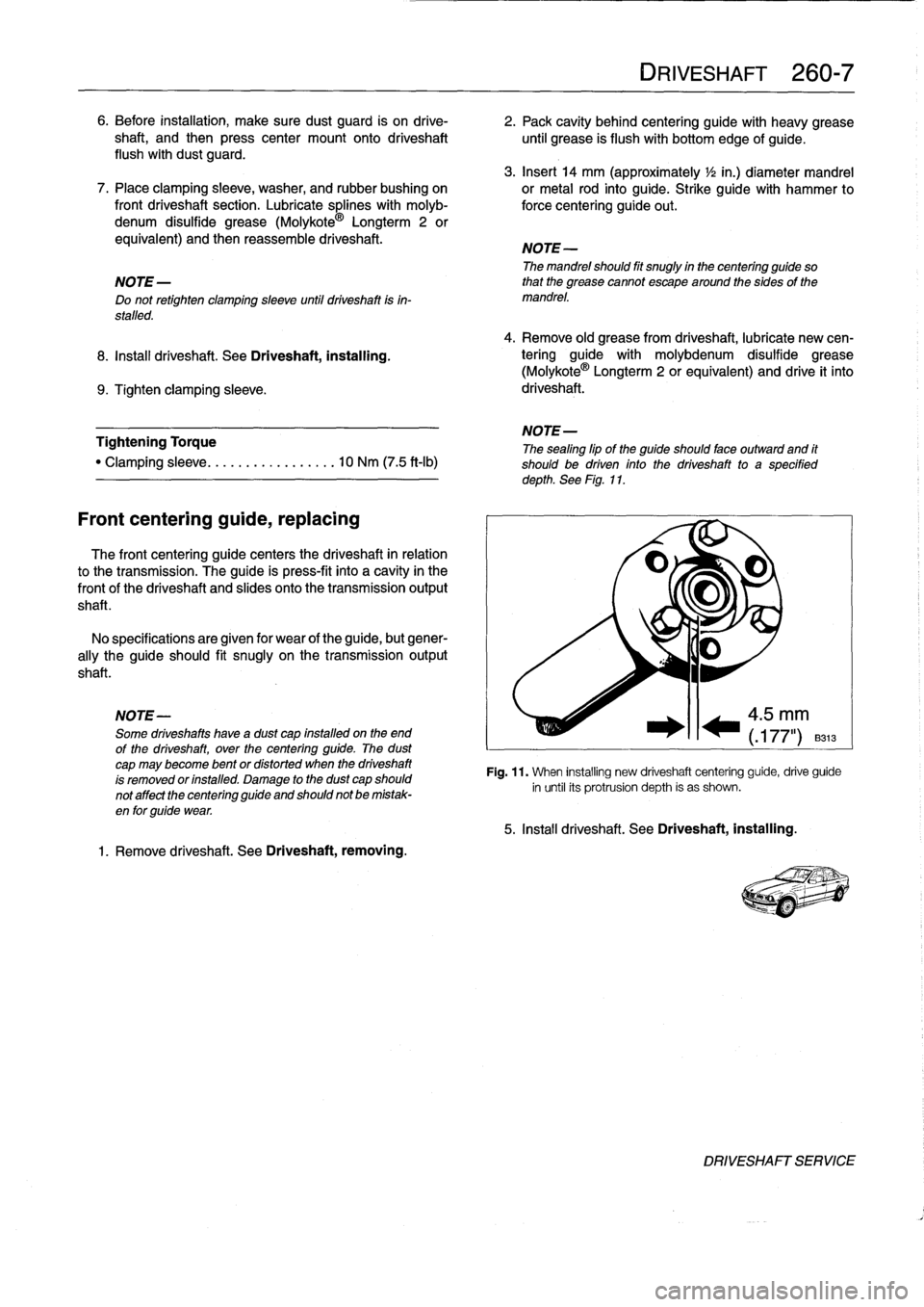
Fig
.
11
.
When
installing
new
driveshaft
centering
guide,
drive
guide
in
until
its
protrusion
depth
is
as
shown
.
5
.
Install
driveshaft
.
See
Driveshaft,
installing
.
DRIVESHAFT
SERVICE
Page 253 of 759
NOTE-
The
traction
control
system
referred
to
as
AST
(all
sea-
son
traction)
may
also
be
referred
to
as
ASC
(Automat-
ic
Stability
Control)
and
ASC+T
(Automatic
Stability
Control+Traction)
.
The
AST
system
improves
traction
by
electronically
apply-
ing
the
rear
brakes
when
therear
drive
wheels
are
spinning
at
a
faster
rate
than
the
front
wheels
.
The
combined
ABS/AST
control
module,
operating
through
the
ABS
hydraulic
control
unit,
modulates
braking
force
at
therear
wheels
.
In
addition,
AST
uses
retarded
ignition
timing
and
an
auxil-iary
engine
throttle
plate
to
reduceengine
torque
and
maintain
vehicle
stability
.
The
auxiliary
throttle
plate
is
held
open
by
spring
pressure
.
The
AST
system
actívates
the
auxiliary
throttie
position
motor
(ADS)
to
cose
the
AST
throttle
as
needed
.
This
reduces
the
volume
of
engine
intake
air
.
Due
to
the
throttle
closing
very
rapidly
during
AST
operationthe
driver
cannot
increase
theengine
power
output
regardless
of
how
far
theaccelerator
pedal
is
pushed
to
the
floor
.
The
auxiliary
throttle
plate
is
placed
ahead
of
the
conven-
tional
throttle
plate
in
the
throttle
body
.
Traction
control
also
comes
into
operationduringdecelera-
tion
.
Decelerating
on
snowy
or
icy
road
surfaces
can
lead
to
rear
wheel
slip
.
If
a
rear
wheel
startsto
drag
or
lock
up
when
the
throttle
is
closed
rapidly
orduringdownshifting,the
AST
system
can
limit
the
problem
by
advancing
the
ignition
timing
.
A
switch
on
the
center
console
is
used
to
togglethe
AST
on
or
off
.
The
AST
system
is
designed
to
be
maintenance
free
.
There
are
no
adjustments
that
can
be
made
.
Repair
and
trouble-
shooting
of
the
AST
system
requires
special
test
equipment
andknowledgeand
should
be
performed
only
by
an
autho-
rized
BMW
dealer
.
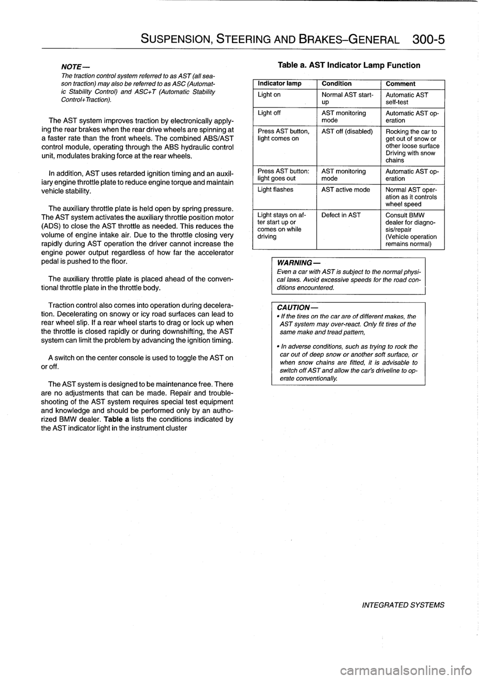
Table
a
lists
theconditions
indicated
by
the
AST
indicator
light
in
the
instrument
cluster
SUSPENSION,
STEERING
AND
BRAKES-GENERAL
300-5
Tablea
.
AST
Indicator
Lamp
Function
Indicator
lamp
1
Condition
1
Comment
Light
on
Normal
AST
start-
Automatic
AST
up
self-test
Light
off
AST
monitoring
Automatic
AST
op-
mode
eration
Press
AST
button,
AST
off
(disabled)
Rocking
the
car
tolight
comes
on
getout
of
snow
or
other
loose
surface
Driving
with
snow
chains
Press
AST
button
:
AST
monitoring
Automatic
AST
op-
light
goes
out
I
mode
eration
Light
flashes
AST
active
mode
I
Normal
AST
oper-
ation
as
it
controls
wheel
speed
Light
stays
on
af-
Defect
in
AST
Consult
BMW
ter
start
up
or
dealer
for
diagno-
comes
on
while
sis/repair
driving
(Vehicle
operation
remains
normal)
WARNING
-
Even
a
car
with
AST
is
subject
to
the
normal
physi-
cal
laws
.
Avoid
excessive
speeds
for
the
road
con-
ditions
encountered
.
CAUTION-
"
If
the
tires
on
the
carare
of
different
makes,
the
AST
system
may
over-react
.
Only
fit
tires
of
the
same
make
and
tread
pattem,
"In
adverse
conditions,
such
as
trying
to
rock
the
car
outof
deep
snow
or
another
soft
surface,
or
when
snow
chainsare
fitted,
it
is
advisable
to
switch
off
AST
and
allow
the
cars
driveline
to
op-
erate
conventionally
.
INTEGRATED
SYSTEMS