ESP BMW M5 2013 F10 User Guide
[x] Cancel search | Manufacturer: BMW, Model Year: 2013, Model line: M5, Model: BMW M5 2013 F10Pages: 230, PDF Size: 6.34 MB
Page 46 of 230
▷When a seat position switch is pressed.▷When a button of the seat, mirror, and
steering wheel memory is pressed briefly.
Activating the setting
1."Settings"2."Doors/key"3."Last seat position autom."
Alarm system
The conceptThe vehicle alarm system responds to:
▷Opening of a door, the hood or the trunk
lid.▷Movements in the vehicle.▷Changes in the vehicle tilt, e.g., during at‐
tempts to steal a wheel or when towing the
car.▷Interruptions in battery voltage.
The alarm system briefly indicates tampering:
▷By sounding an acoustic alarm.▷By switching on the hazard warning sys‐
tem.▷By flashing the high beams.
Arming and disarming the alarm
system
General information
When you lock or unlock the vehicle, either
with the remote control, Comfort Access or at
the door lock the alarm system is armed or dis‐
armed at the same time.
Door lock and armed alarm systemUnlocking via the door lock will trigger the
alarm on some country-specific versions.
In order to terminate this alarm, unlock vehicle
with the remote control or switch on the igni‐
tion, if necessary, by emergency detection of
the remote control.
Trunk lid and armed alarm system The trunk lid can be opened even when the
alarm system is armed.
Press the button on the remote con‐
trol for approx. 1 second.
With Comfort Access the trunk lid opens with
no-touch activation, refer to page 40.
After the trunk lid is closed, it is locked and
monitored again if the doors are locked. The
hazard warning system flashes once.
In some vehicle equipment variants, the trunk
lid can only be opened using the remote con‐
trol if the vehicle was unlocked first.
Panic mode You can trigger the alarm system if you find
yourself in a dangerous situation.
Press the button on the remote con‐
trol for at least 3 seconds.
To switch off the alarm: press any button.
Switching off the alarm▷Unlock the vehicle using the remote con‐
trol.▷With Comfort Access: If you are carrying
the remote control with you, pull on the
driver side or front passenger side door
handle.Seite 42ControlsOpening and closing42
Online Edition for Part no. 01 40 2 909 953 - VI/13
Page 47 of 230
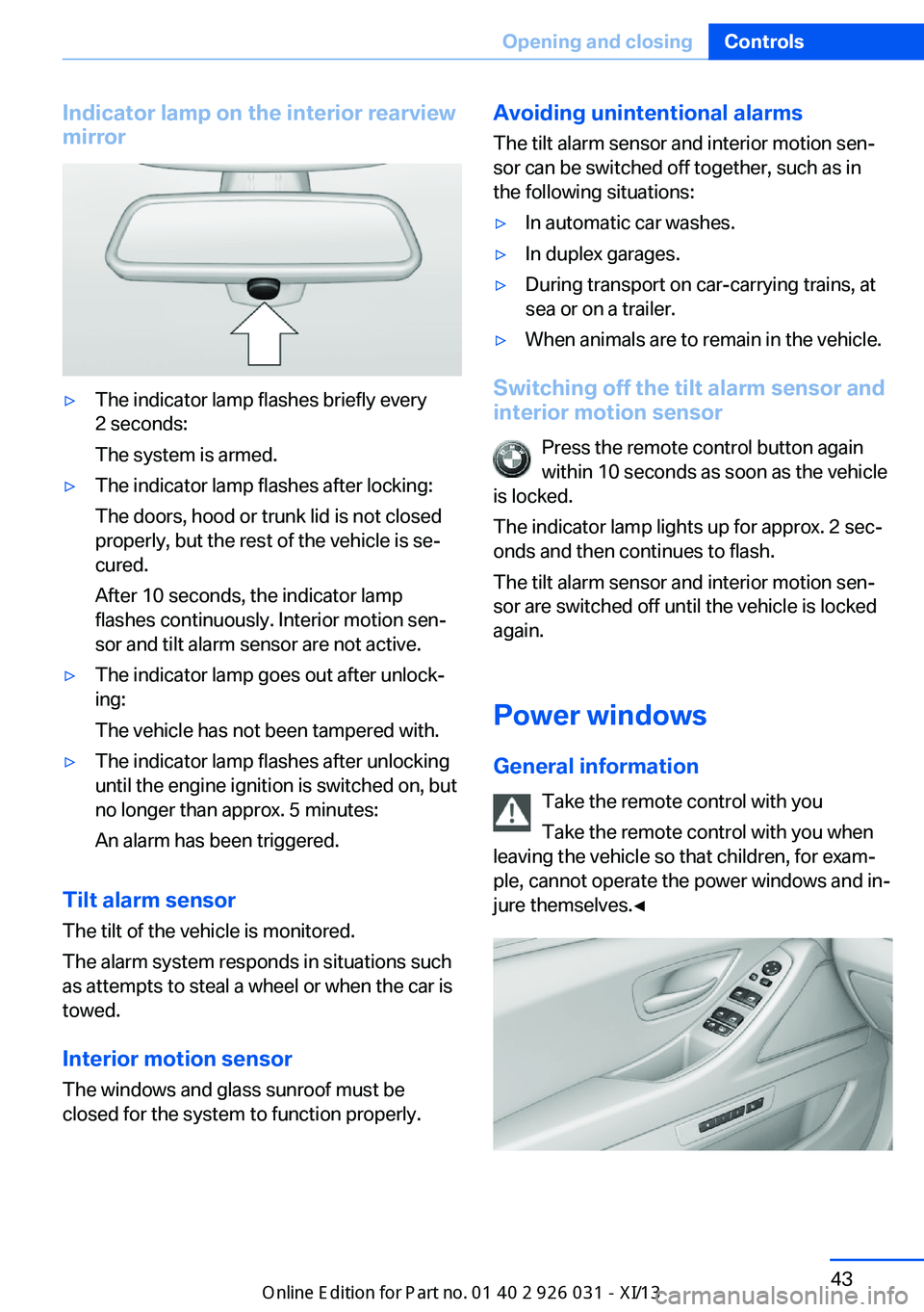
Indicator lamp on the interior rearview
mirror▷The indicator lamp flashes briefly every
2 seconds:
The system is armed.▷The indicator lamp flashes after locking:
The doors, hood or trunk lid is not closed
properly, but the rest of the vehicle is se‐
cured.
After 10 seconds, the indicator lamp
flashes continuously. Interior motion sen‐
sor and tilt alarm sensor are not active.▷The indicator lamp goes out after unlock‐
ing:
The vehicle has not been tampered with.▷The indicator lamp flashes after unlocking
until the engine ignition is switched on, but
no longer than approx. 5 minutes:
An alarm has been triggered.
Tilt alarm sensor The tilt of the vehicle is monitored.
The alarm system responds in situations such
as attempts to steal a wheel or when the car is
towed.
Interior motion sensor The windows and glass sunroof must be
closed for the system to function properly.
Avoiding unintentional alarms
The tilt alarm sensor and interior motion sen‐
sor can be switched off together, such as in
the following situations:▷In automatic car washes.▷In duplex garages.▷During transport on car-carrying trains, at
sea or on a trailer.▷When animals are to remain in the vehicle.
Switching off the tilt alarm sensor and
interior motion sensor
Press the remote control button again
within 10 seconds as soon as the vehicle
is locked.
The indicator lamp lights up for approx. 2 sec‐
onds and then continues to flash.
The tilt alarm sensor and interior motion sen‐
sor are switched off until the vehicle is locked
again.
Power windows
General information Take the remote control with you
Take the remote control with you when
leaving the vehicle so that children, for exam‐
ple, cannot operate the power windows and in‐
jure themselves.◀
Seite 43Opening and closingControls43
Online Edition for Part no. 01 40 2 909 953 - VI/13
Page 50 of 230
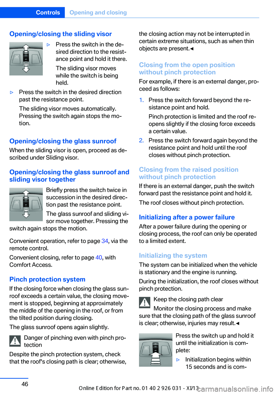
Opening/closing the sliding visor▷Press the switch in the de‐
sired direction to the resist‐
ance point and hold it there.
The sliding visor moves
while the switch is being
held.▷Press the switch in the desired direction
past the resistance point.
The sliding visor moves automatically.
Pressing the switch again stops the mo‐
tion.
Opening/closing the glass sunroof
When the sliding visor is open, proceed as de‐
scribed under Sliding visor.
Opening/closing the glass sunroof and
sliding visor together
Briefly press the switch twice in
succession in the desired direc‐
tion past the resistance point.
The glass sunroof and sliding vi‐
sor move together. Pressing the
switch again stops the motion.
Convenient operation, refer to page 34, via the
remote control.
Convenient closing, refer to page 40, with
Comfort Access.
Pinch protection system
If the closing force when closing the glass sun‐
roof exceeds a certain value, the closing move‐
ment is stopped, beginning at approximately
the middle of the opening in the roof, or from
the tilted position during closing.
The glass sunroof opens again slightly.
Danger of pinching even with pinch pro‐
tection
Despite the pinch protection system, check
that the roof's closing path is clear; otherwise,
the closing action may not be interrupted in
certain extreme situations, such as when thin
objects are present.◀
Closing from the open position
without pinch protection
For example, if there is an external danger, pro‐
ceed as follows:1.Press the switch forward beyond the re‐
sistance point and hold.
Pinch protection is limited and the roof re‐
opens slightly if the closing force exceeds
a certain value.2.Press the switch forward again beyond the
resistance point and hold until the roof
closes without pinch protection.
Closing from the raised position
without pinch protection
If there is an external danger, push the switch
forward past the resistance point and hold it.
The roof closes without pinch protection.
Initializing after a power failure After a power failure during the opening or
closing process, the roof can only be operated
to a limited extent.
Initializing the system
The system can be initialized when the vehicle
is stationary and the engine is running.
During the initialization, the roof closes without
pinch protection.
Keep the closing path clear
Monitor the closing process and make
sure that the closing path of the glass sunroof
is clear; otherwise, injuries may result.◀
Press the switch up and hold it
until the initialization is com‐
plete:
▷Initialization begins within
15 seconds and is com‐Seite 46ControlsOpening and closing46
Online Edition for Part no. 01 40 2 909 953 - VI/13
Page 52 of 230
AdjustingVehicle equipment
All standard, country-specific and optional
equipment that is offered in the model series is
described in this chapter. Therefore, equip‐
ment is also described that is not available in a
vehicle, e. g., because of the selected optional
equipment or country variant. This also applies
for safety-related functions and systems.
Sitting safely The ideal seating position can make a vital
contribution to relaxed, fatigue-free driving.
The seating position plays an important role in
an accident in combination with:▷Safety belts, refer to page 51.▷Head restraints, refer to page 52.▷Airbags, refer to page 97.
Seats
General information Do not adjust the seat while driving
Do not adjust the driver's seat while driv‐
ing, or the seat could respond with unexpected
movement and the ensuing loss of vehicle
control could lead to an accident.◀
Do not incline the backrest too far to the
rear
Also on the front passenger side, do not incline
the backrest on the front passenger side too
far to the rear during driving, or there is a risk of
slipping under the safety belt in the event of an
accident. This would eliminate the protection
normally provided by the belt.◀
Electrically adjustable seats
At a glance1Thigh support2Forward/back, height, tilt3Shoulder support4Backrest width5Lumbar support6Backrest
Note The seat setting for the driver's seat is stored
for the remote control currently in use. When
the vehicle is unlocked via the remote control,
the position is automatically retrieved if the
Function, refer to page 41, for this is activated.
Adjustments in detail
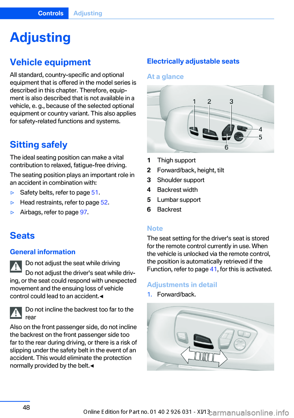
1.Forward/back.Seite 48ControlsAdjusting48
Online Edition for Part no. 01 40 2 909 953 - VI/13
Page 58 of 230
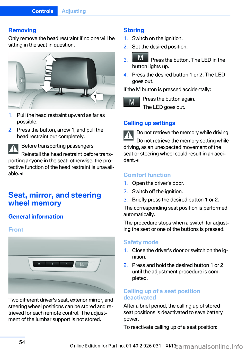
RemovingOnly remove the head restraint if no one will be
sitting in the seat in question.1.Pull the head restraint upward as far as
possible.2.Press the button, arrow 1, and pull the
head restraint out completely.
Before transporting passengers
Reinstall the head restraint before trans‐
porting anyone in the seat; otherwise, the pro‐
tective function of the head restraint is unavail‐
able.◀
Seat, mirror, and steering
wheel memory
General information
Front
Two different driver's seat, exterior mirror, and
steering wheel positions can be stored and re‐
trieved for each remote control. The adjust‐
ment of the lumbar support is not stored.
Storing1.Switch on the ignition.2.Set the desired position.3. Press the button. The LED in the
button lights up.4.Press the desired button 1 or 2. The LED
goes out.
If the M button is pressed accidentally:
Press the button again.
The LED goes out.
Calling up settings Do not retrieve the memory while driving
Do not retrieve the memory setting while
driving, as an unexpected movement of the
seat or steering wheel could result in an acci‐
dent.◀
Comfort function
1.Open the driver's door.2.Switch off the ignition.3.Briefly press the desired button 1 or 2.
The corresponding seat position is performed
automatically.
The procedure stops when a switch for adjust‐
ing the seat or one of the buttons is pressed.
Safety mode
1.Close the driver's door or switch on the ig‐
nition.2.Press and hold the desired button 1 or 2
until the adjustment procedure is com‐
pleted.
Calling up of a seat position
deactivated
After a brief period, the calling up of stored
seat positions is deactivated to save battery
power.
To reactivate calling up of a seat position:
Seite 54ControlsAdjusting54
Online Edition for Part no. 01 40 2 909 953 - VI/13
Page 59 of 230
▷Open or close the door or trunk lid.▷Press a button on the remote control.▷Press the Start/Stop button.
Mirrors
Exterior mirrors
At a glance
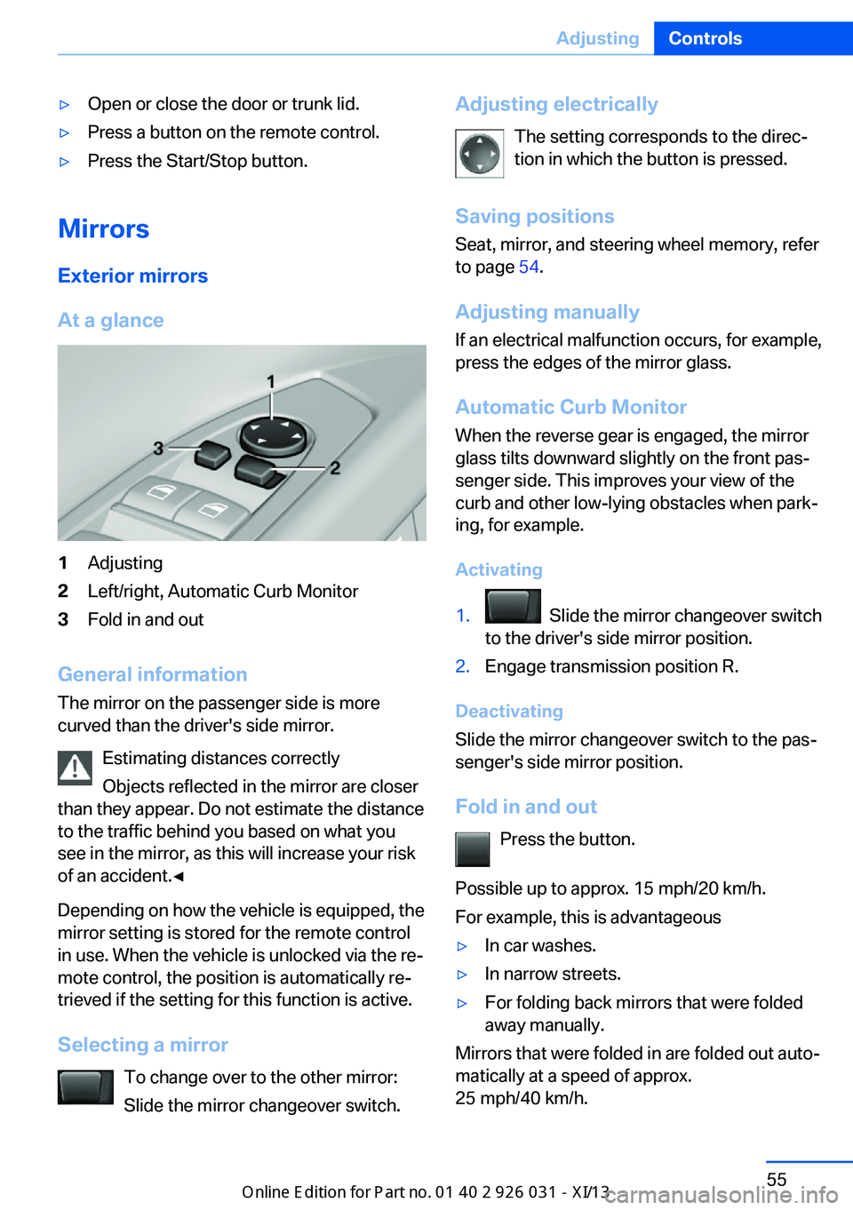
1Adjusting2Left/right, Automatic Curb Monitor3Fold in and out
General information
The mirror on the passenger side is more
curved than the driver's side mirror.
Estimating distances correctly
Objects reflected in the mirror are closer
than they appear. Do not estimate the distance
to the traffic behind you based on what you
see in the mirror, as this will increase your risk
of an accident.◀
Depending on how the vehicle is equipped, the
mirror setting is stored for the remote control
in use. When the vehicle is unlocked via the re‐
mote control, the position is automatically re‐
trieved if the setting for this function is active.
Selecting a mirror To change over to the other mirror:Slide the mirror changeover switch.
Adjusting electrically
The setting corresponds to the direc‐
tion in which the button is pressed.
Saving positions
Seat, mirror, and steering wheel memory, refer
to page 54.
Adjusting manually If an electrical malfunction occurs, for example,
press the edges of the mirror glass.
Automatic Curb Monitor
When the reverse gear is engaged, the mirror
glass tilts downward slightly on the front pas‐
senger side. This improves your view of the
curb and other low-lying obstacles when park‐
ing, for example.
Activating1. Slide the mirror changeover switch
to the driver's side mirror position.2.Engage transmission position R.
Deactivating
Slide the mirror changeover switch to the pas‐
senger's side mirror position.
Fold in and out Press the button.
Possible up to approx. 15 mph/20 km/h.
For example, this is advantageous
▷In car washes.▷In narrow streets.▷For folding back mirrors that were folded
away manually.
Mirrors that were folded in are folded out auto‐
matically at a speed of approx.
25 mph/40 km/h.
Seite 55AdjustingControls55
Online Edition for Part no. 01 40 2 909 953 - VI/13
Page 62 of 230
Activating/deactivating M Drive
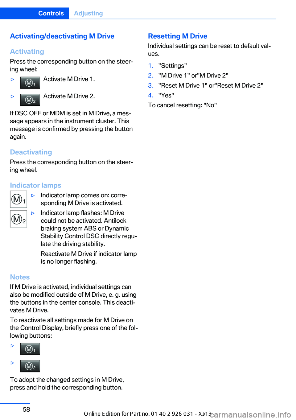
Activating Press the corresponding button on the steer‐
ing wheel:▷Activate M Drive 1.▷Activate M Drive 2.
If DSC OFF or MDM is set in M Drive, a mes‐
sage appears in the instrument cluster. This
message is confirmed by pressing the button
again.
Deactivating Press the corresponding button on the steer‐
ing wheel.
Indicator lamps
▷Indicator lamp comes on: corre‐
sponding M Drive is activated.▷Indicator lamp flashes: M Drive
could not be activated. Antilock
braking system ABS or Dynamic
Stability Control DSC directly regu‐
late the driving stability.
Reactivate M Drive if indicator lamp
is no longer flashing.
Notes
If M Drive is activated, individual settings can also be modified outside of M Drive, e. g. using
the buttons in the center console. This deacti‐
vates M Drive.
To reactivate all settings made for M Drive on
the Control Display, briefly press one of the fol‐
lowing buttons:
▷▷
To adopt the changed settings in M Drive,
press and hold the corresponding button.
Resetting M Drive
Individual settings can be reset to default val‐
ues.1."Settings"2."M Drive 1" or"M Drive 2"3."Reset M Drive 1" or"Reset M Drive 2"4."Yes"
To cancel resetting: "No"
Seite 58ControlsAdjusting58
Online Edition for Part no. 01 40 2 909 953 - VI/13
Page 77 of 230
Engaging the transmission position
Pull or push lever in the corresponding direc‐
tion.
As soon as the selector lever is released, it re‐
verts to the center position. In position R, the
selector lever locks.
The engaged transmission position is dis‐
played in the instrument cluster and on the se‐
lector lever.
With the transmission position engaged, the
vehicle can be moved very slowly when ma‐
neuvering or in stop and go traffic. To do this,
depress the accelerator briefly while the vehi‐
cle is stationary.
Shift lock
To shift out of neutral, apply the brake while
the vehicle is stationary.
R is Reverse
Select only when the vehicle is stationary.
It is also possible to rock the vehicle up to
6 mph/10 km/h. To do this, switch between
forward and reverse gear.
N is Neutral Use in automatic car washes, for example. The
vehicle can then roll.
S Sequential mode
Use the shift paddles or the shift lever to up‐
shift or downshift without letting off the gas.
Automatic Functions:▷Upshifting or downshifting is done only if
the rpm and vehicle speed are appropriate.
For example, there is no downshifting if the
engine speed is too high.▷Shortly before falling below a gear-de‐
pendent minimum speed, the transmission
is automatically downshifted.
It is also possible to start out in 2nd gear, e. g.
on icy roads.
Kickdown: for maximum acceleration, e. g.
when passing. To do this, depress the acceler‐
ator pedal past the resistance point, and pull
the left shift paddle once or push the shift lever
forward once.
Switch to Drive mode: push selector lever in
D/S direction.
D Drive mode In Drive mode, all forward gears are automati‐
cally changed.
Kickdown: for maximum acceleration, e. g.
when passing. To do this, depress the acceler‐
ator pedal past the resistance point.
Switch to Sequential mode: shift using the
shift paddles or the selector lever, or push the
selector lever in the D/S direction.
P Park
The drive wheels are blocked.
P is engaged automatically:▷After the engine is switched off in ignition
off, refer to page 63, if position R or D is
engaged.▷If the ignition is switched off and position N
is engaged.
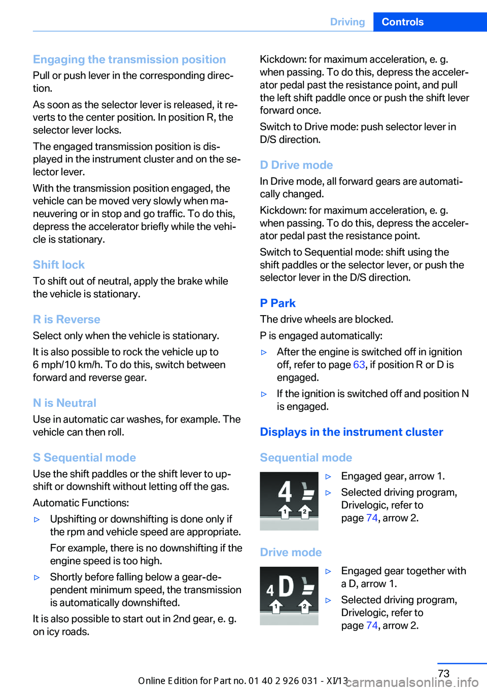
Displays in the instrument cluster
Sequential mode
▷Engaged gear, arrow 1.▷Selected driving program,
Drivelogic, refer to
page 74, arrow 2.
Drive mode
▷Engaged gear together with
a D, arrow 1.▷Selected driving program,
Drivelogic, refer to
page 74, arrow 2.Seite 73DrivingControls73
Online Edition for Part no. 01 40 2 909 953 - VI/13
Page 79 of 230
When M Drive is active, setting is immedi‐
ately applied.
To activate M Drive with the selected settings,
press the corresponding button on the steer‐
ing wheel:
▷▷
Risk of an accident
Use the settings for DSC in M Drive; oth‐
erwise, driving stability may be impaired, and
there is risk of an accident.◀
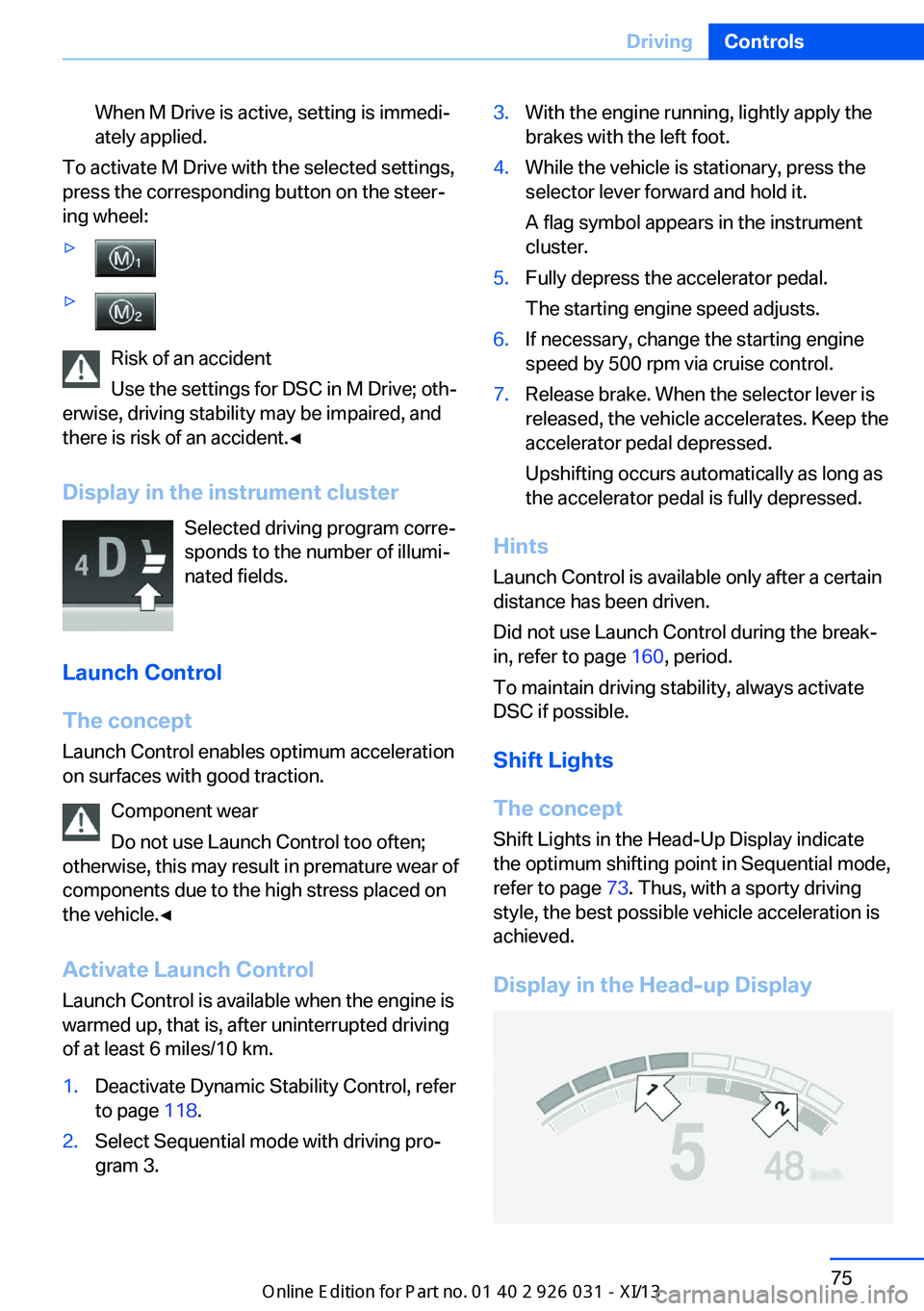
Display in the instrument cluster Selected driving program corre‐
sponds to the number of illumi‐
nated fields.
Launch Control
The concept Launch Control enables optimum accelerationon surfaces with good traction.
Component wear
Do not use Launch Control too often;
otherwise, this may result in premature wear of
components due to the high stress placed on
the vehicle.◀
Activate Launch Control Launch Control is available when the engine is
warmed up, that is, after uninterrupted driving
of at least 6 miles/10 km.
1.Deactivate Dynamic Stability Control, refer
to page 118.2.Select Sequential mode with driving pro‐
gram 3.3.With the engine running, lightly apply the
brakes with the left foot.4.While the vehicle is stationary, press the
selector lever forward and hold it.
A flag symbol appears in the instrument
cluster.5.Fully depress the accelerator pedal.
The starting engine speed adjusts.6.If necessary, change the starting engine
speed by 500 rpm via cruise control.7.Release brake. When the selector lever is
released, the vehicle accelerates. Keep the
accelerator pedal depressed.
Upshifting occurs automatically as long as
the accelerator pedal is fully depressed.
Hints
Launch Control is available only after a certain
distance has been driven.
Did not use Launch Control during the break-
in, refer to page 160, period.
To maintain driving stability, always activate
DSC if possible.
Shift Lights
The concept
Shift Lights in the Head-Up Display indicate
the optimum shifting point in Sequential mode,
refer to page 73. Thus, with a sporty driving
style, the best possible vehicle acceleration is
achieved.
Display in the Head-up Display
Seite 75DrivingControls75
Online Edition for Part no. 01 40 2 909 953 - VI/13
Page 80 of 230
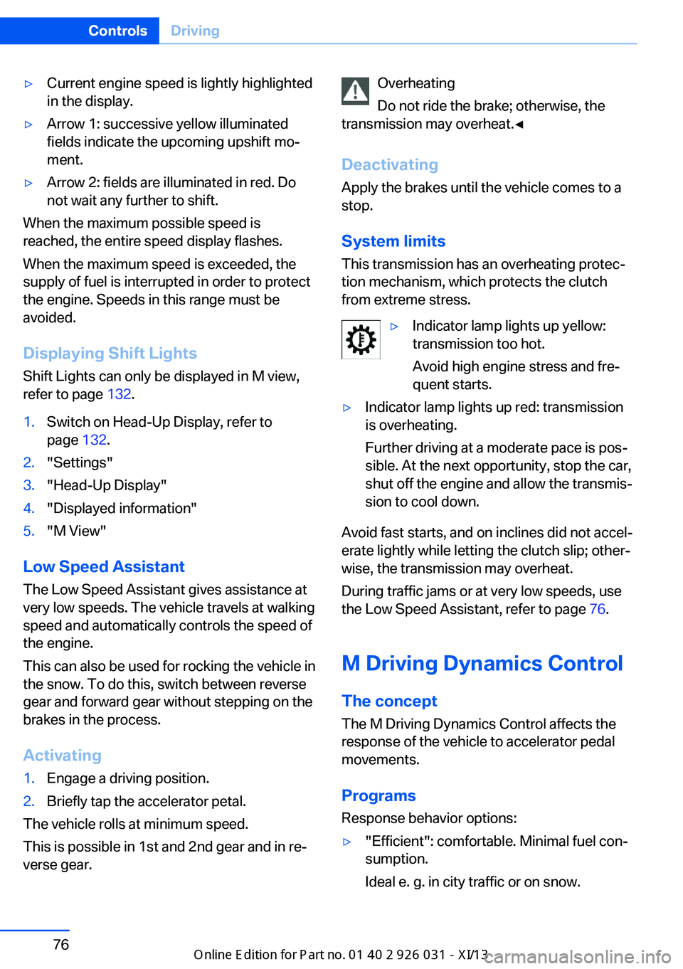
▷Current engine speed is lightly highlighted
in the display.▷Arrow 1: successive yellow illuminated
fields indicate the upcoming upshift mo‐
ment.▷Arrow 2: fields are illuminated in red. Do
not wait any further to shift.
When the maximum possible speed is
reached, the entire speed display flashes.
When the maximum speed is exceeded, the
supply of fuel is interrupted in order to protect
the engine. Speeds in this range must be
avoided.
Displaying Shift LightsShift Lights can only be displayed in M view,
refer to page 132.
1.Switch on Head-Up Display, refer to
page 132.2."Settings"3."Head-Up Display"4."Displayed information"5."M View"
Low Speed Assistant
The Low Speed Assistant gives assistance at
very low speeds. The vehicle travels at walking
speed and automatically controls the speed of
the engine.
This can also be used for rocking the vehicle in
the snow. To do this, switch between reverse
gear and forward gear without stepping on the
brakes in the process.
Activating
1.Engage a driving position.2.Briefly tap the accelerator petal.
The vehicle rolls at minimum speed.
This is possible in 1st and 2nd gear and in re‐
verse gear.
Overheating
Do not ride the brake; otherwise, the
transmission may overheat.◀
DeactivatingApply the brakes until the vehicle comes to a
stop.
System limits
This transmission has an overheating protec‐
tion mechanism, which protects the clutch
from extreme stress.▷Indicator lamp lights up yellow:
transmission too hot.
Avoid high engine stress and fre‐
quent starts.▷Indicator lamp lights up red: transmission
is overheating.
Further driving at a moderate pace is pos‐
sible. At the next opportunity, stop the car,
shut off the engine and allow the transmis‐
sion to cool down.
Avoid fast starts, and on inclines did not accel‐
erate lightly while letting the clutch slip; other‐
wise, the transmission may overheat.
During traffic jams or at very low speeds, use
the Low Speed Assistant, refer to page 76.
M Driving Dynamics Control
The concept The M Driving Dynamics Control affects the
response of the vehicle to accelerator pedal
movements.
ProgramsResponse behavior options:
▷"Efficient": comfortable. Minimal fuel con‐
sumption.
Ideal e. g. in city traffic or on snow.Seite 76ControlsDriving76
Online Edition for Part no. 01 40 2 909 953 - VI/13