service BMW M5 SEDAN 2013 User Guide
[x] Cancel search | Manufacturer: BMW, Model Year: 2013, Model line: M5 SEDAN, Model: BMW M5 SEDAN 2013Pages: 230, PDF Size: 6.29 MB
Page 56 of 230

Safety belt reminder for driver's and
passenger's seat
The indicator lamp flashes or lights up
and a signal sounds. Make sure that
the safety belts are positioned cor‐
rectly. The safety belt reminder is active at
speeds above approx. 5 mph/8 km/h. It can
also be activated if objects are placed on the
front passenger seat.
Damage to safety belts In the case of strain caused by accidents or
damage:
Have the safety belts, including the safety belt
tensioners, replaced and have the belt anchors checked.
Checking and replacing safety belts
Have the work performed only by your
service center; otherwise, it cannot be ensured
that this safety feature will function properly.◀
Front head restraints
Correctly adjusted head restraint A correctly adjusted head restraint reduces the
risk of injury to cervical vertebrae in the event
of an accident.
Adjusting the head restraint
Correctly adjust the head restraints of all
occupied seats; otherwise, there is an in‐ creased risk of injury in an accident.◀
Height
Adjust the head restraint so that its center is
approximately at ear level.
Distance
Adjust the distance so that the head restraint
is as close as possible to the back of the head.Active head restraint
In the event of a rear-end collision with a cer‐
tain severity, the active head restraint automat‐
ically reduces the distance from the head.
Reduced protective function▷Do not use seat or head restraint
covers.▷Do not hang objects, e.g., clothes hangers,
on the head restraints.▷Only attach accessories approved by BMW
to the seat or head restraint.
Otherwise, the protective function of the active
head restraint will be impaired and the per‐
sonal safety of the occupants will be endan‐
gered.◀
In the case of strain caused by accidents or
damage:
Have the active headrest checked and if nec‐
essary replaced.
Adjusting the height
Adjusting electrically.
Seite 52ControlsAdjusting52
Online Edition for Part no. 01 40 2 909 953 - VI/13
Page 83 of 230

Electronic displays
Overview, instrument cluster1Messages, e.g. Check Control 79
Time 82
Digital tachometer 822Range 833Computer 884Transmission display, Drivelogic 83
Gear shift indicator 86
Service requirements 84Miles/trip miles 825Selection list, such as for the radio 88
System states of driving dynamics 84
Current fuel consumption 83
Energy recovery 83
External temperature 82
Auto Start/Stop function 65Check Control
The concept The Check Control system monitors functions
in the vehicle and notifies you of malfunctions
in the monitored systems.
A Check Control message is displayed as a
combination of indicator or warning lamps and
text messages in the instrument cluster and in
the Head-up Display.In addition, an acoustic signal may be output
and a text message may appear on the Control Display.
Indicator/warning lamps The indicator and warning lamps in the instru‐
ment cluster can light up in a variety of combi‐
nations and colors.
Several of the lamps are checked for proper
functioning and light up temporarily when the
engine is started or the ignition is switched on.Seite 79DisplaysControls79
Online Edition for Part no. 01 40 2 909 953 - VI/13
Page 85 of 230

The supplementary text of urgent messages is
automatically displayed on the Control Display.
Symbols
Depending on the Check Control message, the
following functions can be selected.▷ "Owner's Manual"
Display additional information about the
Check Control message in the Integrated
Owner's Manual.▷ "Service request"
Contact the service partner.▷ "Roadside Assistance"
Contact Roadside Assistance.
Hiding Check Control messages
Press the computer button on the turn signal
lever.
▷Some Check Control messages are dis‐
played continuously and are not cleared
until the malfunction is eliminated. If sev‐
eral malfunctions occur at once, the mes‐
sages are displayed consecutively.
These messages can be hidden for approx.
8 seconds. After this time, they are dis‐
played again automatically.▷Other Check Control messages are hidden
automatically after approx. 20 seconds.
They are stored and can be displayed
again later.Displaying stored Check Control
messages1."Vehicle Info"2."Vehicle status"3. "Check Control"4.Select the text message.
Messages after trip completion
Special messages that are displayed during
driving are displayed again after the ignition is
switched off.
Fuel gauge The vehicle inclination may
cause the display to vary.
US models: the arrow beside the
fuel pump symbol shows which
side of the vehicle the fuel filler
flap is on.
Hints on refueling, refer to page 172.
Tachometer Always avoid engine speeds inthe red warning field. In this
range, the fuel supply is inter‐
rupted to protect the engine.
Engine oil temperature
▷Cold engine: the pointer is at
the low temperature end.
Drive at moderate engine
and vehicle speeds.▷Normal operating tempera‐
ture: the pointer is in the
middle or in the left half of
the temperature display.Seite 81DisplaysControls81
Online Edition for Part no. 01 40 2 909 953 - VI/13
Page 88 of 230

EfficientDynamics displayInformation on fuel consumption and technol‐
ogy can be displayed during driving.1."Vehicle Info"2."EfficientDynamics"
Displaying fuel consumption history
The average fuel consumption can be dis‐
played within an adjustable time frame.
"Consumption history"
Adjusting fuel consumption history time frame
Select the symbol.
Resetting fuel consumption history
1.Open "Options".2."Reset consumption history"
Displaying EfficientDynamics info
The current efficiency can be displayed.
"EfficientDynamics info"
The following systems are displayed:
▷Automatic engine Start/Stop function.▷Energy recovery.▷Climate control output.
Driving dynamics systems
The system states of the driving
dynamics are displayed in the
instrument cluster.
SymbolsDescriptionEngine Dynamics Control, refer to
page 76.Electronic Damper Control EDC,
refer to page 119.Servotronic, refer to page 120.
Activate display
1."Settings"2."Info display"3.If necessary. "M dynamic driving syst."
The display for the Driving Dynamics
System is active.
Display Current fuel consumption, refer
to page 83, and Energy recovery, refer to
page 83.
Service requirements
Display The driving distance or the time
to the next scheduled mainte‐
nance is displayed briefly after
the ignition is switched on.
The current service require‐
ments can be read out from the remote control
by the service specialist.
With TeleService, data regarding the service
status or legally mandated inspections of your
vehicle are automatically transmitted to your
service center before the service due date.
Seite 84ControlsDisplays84
Online Edition for Part no. 01 40 2 909 953 - VI/13
Page 89 of 230
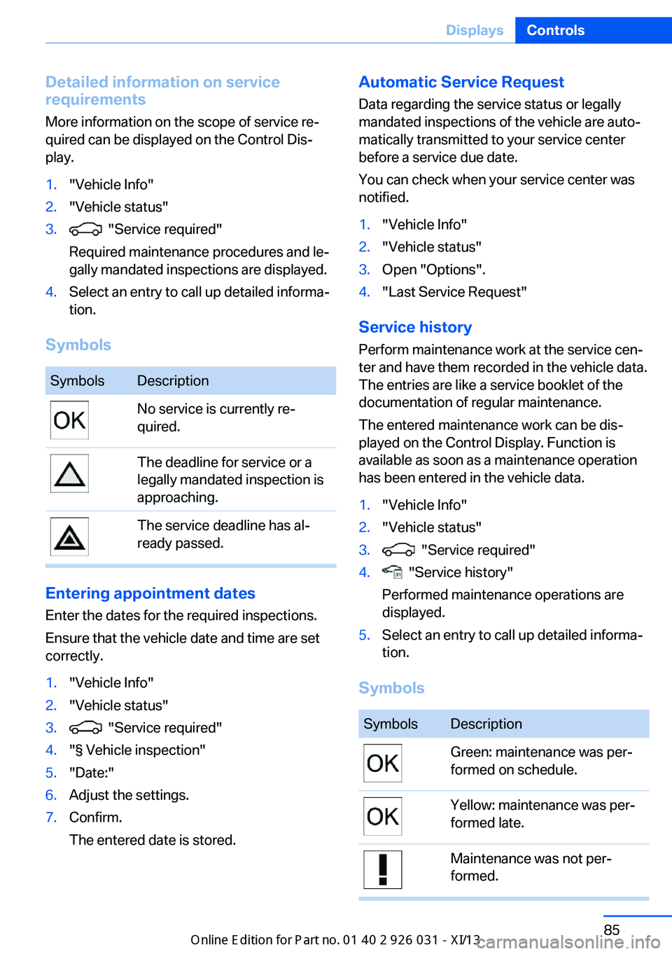
Detailed information on service
requirements
More information on the scope of service re‐
quired can be displayed on the Control Dis‐
play.1."Vehicle Info"2."Vehicle status"3. "Service required"
Required maintenance procedures and le‐
gally mandated inspections are displayed.4.Select an entry to call up detailed informa‐
tion.
Symbols
SymbolsDescriptionNo service is currently re‐
quired.The deadline for service or a
legally mandated inspection is
approaching.The service deadline has al‐
ready passed.
Entering appointment dates
Enter the dates for the required inspections.
Ensure that the vehicle date and time are set
correctly.
1."Vehicle Info"2."Vehicle status"3. "Service required"4."§ Vehicle inspection"5."Date:"6.Adjust the settings.7.Confirm.
The entered date is stored.Automatic Service Request
Data regarding the service status or legally
mandated inspections of the vehicle are auto‐
matically transmitted to your service center
before a service due date.
You can check when your service center was
notified.1."Vehicle Info"2."Vehicle status"3.Open "Options".4."Last Service Request"
Service history
Perform maintenance work at the service cen‐
ter and have them recorded in the vehicle data.
The entries are like a service booklet of the
documentation of regular maintenance.
The entered maintenance work can be dis‐
played on the Control Display. Function is
available as soon as a maintenance operation
has been entered in the vehicle data.
1."Vehicle Info"2."Vehicle status"3. "Service required"4. "Service history"
Performed maintenance operations are
displayed.5.Select an entry to call up detailed informa‐
tion.
Symbols
SymbolsDescriptionGreen: maintenance was per‐
formed on schedule.Yellow: maintenance was per‐
formed late.Maintenance was not per‐
formed.Seite 85DisplaysControls85
Online Edition for Part no. 01 40 2 909 953 - VI/13
Page 102 of 230

Protective action
Airbags are not triggered in every impact situa‐
tion, e.g., in less severe accidents or rear-end
collisions.
Information on how to ensure the optimal
protective effect of the airbags▷Keep at a distance from the airbags.▷Always grasp the steering wheel on the
steering wheel rim, holding your hands at
the 3 o'clock and 9 o'clock positions, to
keep the danger of injury to your hands or
arms as low as possible if the airbag is trig‐
gered.▷There should be no people, animals, or ob‐
jects between an airbag and a person.▷Do not use the cover of the front airbag on
the front passenger side as a storage area.▷Keep the dashboard and window on the
front passenger side clear, i.e., do not
cover with adhesive labels or coverings,
and do not attach holders such as for navi‐
gation instruments and mobile phones.▷Make sure that the front passenger is sit‐
ting correctly, i.e., keeps his or her feet and
legs in the footwell; otherwise, leg injuries
can occur if the front airbag is triggered.▷Do not place slip covers, seat cushions or
other objects on the front passenger seat
that are not approved specifically for seats
with integrated side airbags.▷Do not hang pieces of clothing, such as
jackets, over the backrests.▷Make sure that occupants keep their heads
away from the side airbag and do not rest
against the head airbag; otherwise, injuries
can occur if the airbags are triggered.▷Do not remove the airbag restraint system.▷Do not remove the steering wheel.▷Do not apply adhesive materials to the air‐
bag cover panels, cover them or modify
them in any way.▷Never modify either the individual compo‐
nents or the wiring in the airbag system.
This also applies to steering wheel covers,
the dashboard, the seats, the roof pillars
and the sides of the headliner.◀
Even when all instructions are followed closely,
injury from contact with the airbags cannot be
ruled out in certain situations.
The ignition and inflation noise may lead to
short-term and, in most cases, temporary
hearing impairment in sensitive individuals.
In the case of a malfunction, deactivation
and after triggering of the airbags
Do not touch the individual components imme‐
diately after the system has been triggered;
otherwise, there is the danger of burns.
Only have the airbags checked, repaired or dis‐
mantled and the airbag generator scrapped by
your service center or a workshop that has the
necessary authorization for handling explo‐
sives.
Non-professional attempts to service the sys‐
tem could lead to failure in an emergency or
undesired triggering of the airbag, either of
which could result in injury.◀
Warnings and information on the airbags are
also found on the sun visors.
Functional readiness of the airbag
system
When the ignition is switch on, the
warning lamp in the instrument cluster
lights up briefly and thereby indicates
the operational readiness of the entire airbag
system and the belt tensioner.
Airbag system malfunctioning
▷Warning lamp does not come on when the
ignition is turned on.▷The warning lamp lights up continuously.Seite 98ControlsSafety98
Online Edition for Part no. 01 40 2 909 953 - VI/13
Page 106 of 230

The tire pressure depends on the temperature
of the tire. If the tire temperature rises, e.g.,
due to driving or because of the heat of the
Sun, the tire inflation pressure increases also.
The tire pressure is reduced when the tire
temperature falls again. This behavior may
cause a warning to be issued if temperatures
fall very sharply.
Malfunction The yellow warning lamp flashes and
then lights up continuously. A Check
Control message is displayed. No flat
tire or loss of tire pressure can be detected.
Display in the following situations:▷A wheel without TPM electronics is fitted:
have the service center check it if neces‐
sary.▷Malfunction: have the system checked by
your service center.▷TPM was unable to complete the reset.
Reset the system again.▷Disturbance by systems or devices with
the same radio frequency: after leaving the
area of the disturbance, the system auto‐
matically becomes active again.
Declaration according to NHTSA/
FMVSS 138 Tire Pressure Monitoring
System
Each tire, including the spare (if provided)
should be checked monthly when cold and in‐
flated to the inflation pressure recommended
by the vehicle manufacturer on the vehicle
placard or tire inflation pressure label. (If your
vehicle has tires of a different size than the size
indicated on the vehicle placard or tire inflation
pressure label, you should determine the
proper tire inflation pressure for those tires.)
As an added safety feature, your vehicle has
been equipped with a tire pressure monitoring
system (TPMS) that illuminates a low tire pres‐
sure telltale when one or more of your tires is
significantly under-inflated. Accordingly, when
the low tire pressure telltale illuminates, you
should stop and check your tires as soon as
possible, and inflate them to the proper pres‐
sure. Driving on a significantly under-inflated
tire causes the tire to overheat and can lead to
tire failure. Under-inflation also reduces fuel ef‐
ficiency and tire tread life, and may affect the
vehicle's handling and stopping ability. Please
note that the TPMS is not a substitute for
proper tire maintenance, and it is the driver's
responsibility to maintain correct tire pressure,
even if under-inflation has not reached the
level to trigger illumination of the TPMS low
tire pressure telltale. Your vehicle has also
been equipped with a TPMS malfunction indi‐
cator to indicate when the system is not oper‐
ating properly. The TPMS malfunction indica‐
tor is combined with the low tire pressure
telltale. When the system detects a malfunc‐
tion, the telltale will flash for approximately one
minute and then remain continuously illumi‐
nated. This sequence will continue upon sub‐
sequent vehicle start-ups as long as the mal‐
function exists. When the malfunction indicator
is illuminated, the system may not be able to
detect or signal low tire pressure as intended.
TPMS malfunctions may occur for a variety of
reasons, including the installation of replace‐
ment or alternate tires or wheels on the vehicle
that prevent the TPMS from functioning prop‐
erly. Always check the TPMS malfunction tell‐
tale after replacing one or more tires or wheels
on your vehicle to ensure that the replacement
or alternate tires and wheels allow the TPMS
to continue to function properly.
FTM Flat Tire Monitor The conceptThe system does not measure the actual infla‐
tion pressure in the tires.
It detects a pressure loss in a tire by comparing
the rotational speeds of the individual wheels
while moving.Seite 102ControlsSafety102
Online Edition for Part no. 01 40 2 909 953 - VI/13
Page 137 of 230

Setting the rotation1."Settings"2."Head-Up Display"3."Rotation"4.Turn the controller.
The setting is stored for the remote control
currently in use.
Special windshield
The windshield is part of the system.
The shape of the windshield makes it possible
to display a precise image.
A film in the windshield prevents double im‐
ages from being displayed.
Therefore, have the special windshield re‐
placed by a service center only.
Seite 133Driving comfortControls133
Online Edition for Part no. 01 40 2 909 953 - VI/13
Page 145 of 230

Interior equipmentVehicle equipmentAll standard, country-specific and optional
equipment that is offered in the model series is
described in this chapter. Therefore, equip‐
ment is also described that is not available in a
vehicle, e. g., because of the selected optional
equipment or country variant. This also applies
for safety-related functions and systems.
Integrated universal remote
control
The conceptThe integrated universal remote control can
operate up to 3 functions of remote-controlled
systems such as garage door drives or lighting
systems. The integrated universal remote con‐
trol replaces up to 3 different hand-held trans‐
mitters. To operate the remote control, the
buttons on the interior rearview mirror must be
programmed with the desired functions. The
hand-held transmitter for the particular system
is required in order to program the remote con‐
trol.
During programming
During programming and before activat‐
ing a device using the integrated universal re‐
mote control, ensure that there are no people,
animals, or objects in the range of movement
of the remote-controlled device; otherwise,
there is a risk of injury or damage.
Also follow the safety instructions of the hand-
held transmitter.◀
Before selling the vehicle, delete the stored
functions for the sake of security.Compatibility
If this symbol is printed on the packag‐
ing or in the instructions of the system
to be controlled, the system is gener‐
ally compatible with the integrated universal
remote control.
If you have any questions, please contact:▷Your service center.▷www.homelink.com on the Internet.
HomeLink is a registered trademark of John‐
son Controls, Inc.
Controls on the interior rearview
mirror
▷LED, arrow 1.▷Buttons, arrow 2.▷The hand-held transmitter, arrow 3, is re‐
quired for programming.
Programming
General information
1.Switch on the ignition.2.Initial setup:
Press and hold the left and right button on
the interior rearview mirror simultaneously
for approximately 20 seconds until the LED
on the interior rearview mirror flashes. ThisSeite 141Interior equipmentControls141
Online Edition for Part no. 01 40 2 909 953 - VI/13
Page 153 of 230

1.Pull the handle forward and lift the ski bag
out.2.Close the cover in the cargo area.
More information on the various inserts availa‐
ble can be obtained from your service center.
Seite 149Interior equipmentControls149
Online Edition for Part no. 01 40 2 909 953 - VI/13