navigation system BMW M6 CONVERTIBLE 2007 E64 Owner's Guide
[x] Cancel search | Manufacturer: BMW, Model Year: 2007, Model line: M6 CONVERTIBLE, Model: BMW M6 CONVERTIBLE 2007 E64Pages: 256, PDF Size: 8.11 MB
Page 73 of 256
Controls
71Reference
At a glance
Driving tips
Communications
Navigation
Entertainment
Mobility
2.Turn the controller to select the distance
to your destination. If necessary, hold it
against a slight resistance to enter a greater
difference.
3.Press the controller to apply the setting.
The distance is automatically predetermined
during the destination guidance of the naviga-
tion system
*.
Trip computer
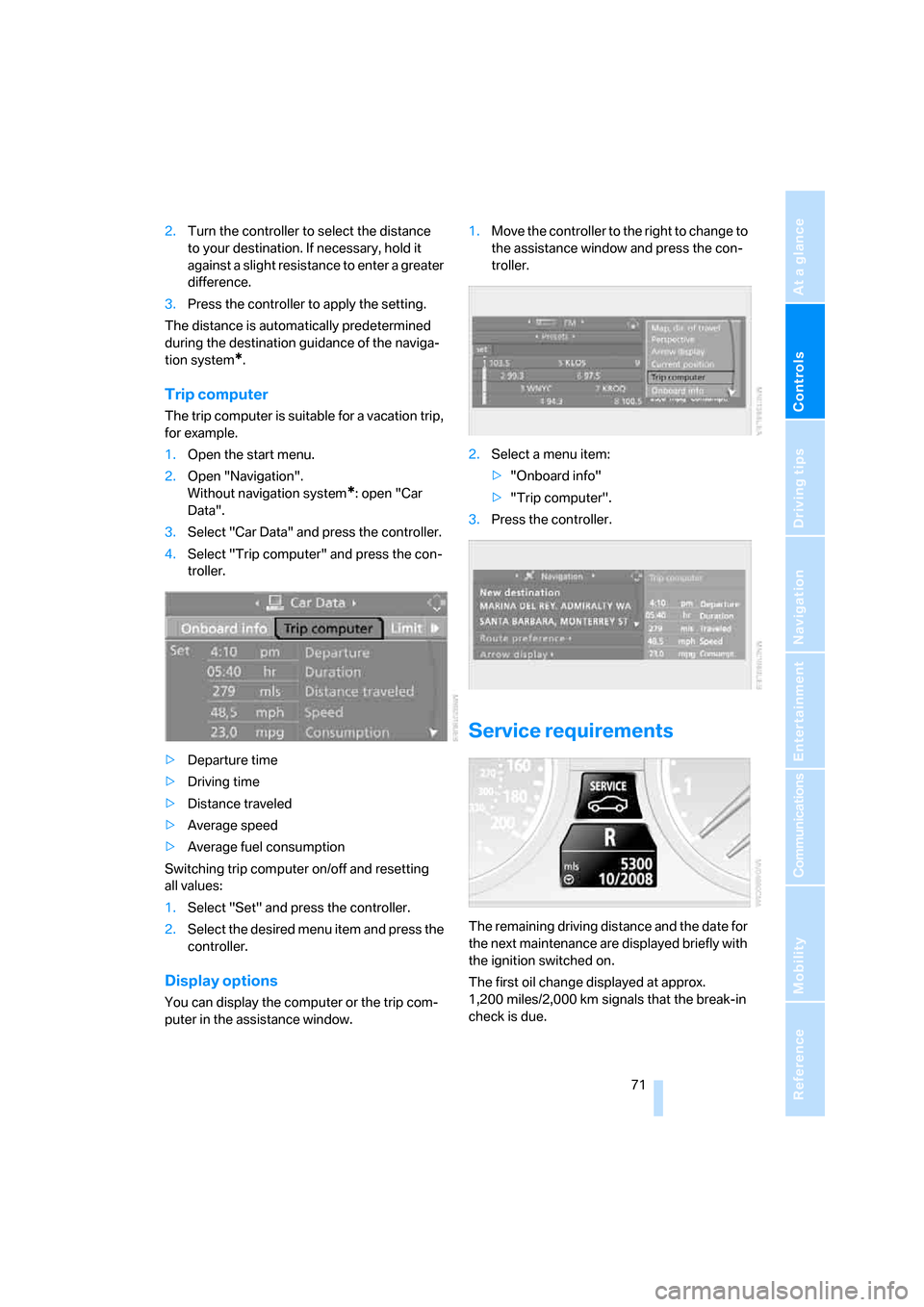
The trip computer is suitable for a vacation trip,
for example.
1.Open the start menu.
2.Open "Navigation".
Without navigation system
*: open "Car
Data".
3.Select "Car Data" and press the controller.
4.Select "Trip computer" and press the con-
troller.
>Departure time
>Driving time
>Distance traveled
>Average speed
>Average fuel consumption
Switching trip computer on/off and resetting
all values:
1.Select "Set" and press the controller.
2.Select the desired menu item and press the
controller.
Display options
You can display the computer or the trip com-
puter in the assistance window.1.Move the controller to the right to change to
the assistance window and press the con-
troller.
2.Select a menu item:
>"Onboard info"
>"Trip computer".
3.Press the controller.
Service requirements
The remaining driving distance and the date for
the next maintenance are displayed briefly with
the ignition switched on.
The first oil change displayed at approx.
1,200 miles/2,000 km signals that the break-in
check is due.
Page 75 of 256
Controls
73Reference
At a glance
Driving tips
Communications
Navigation
Entertainment
Mobility
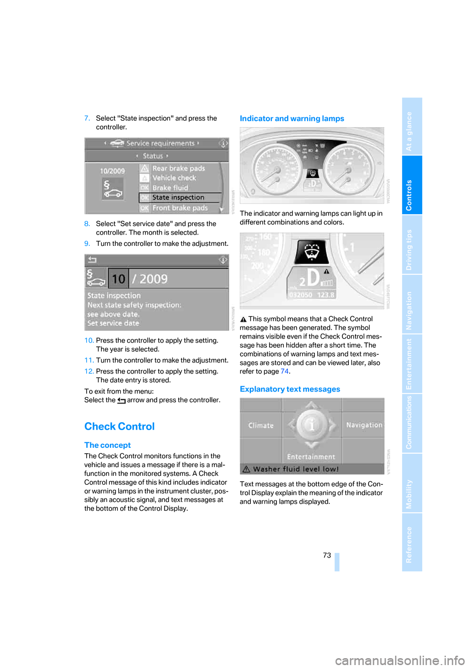
7.Select "State inspection" and press the
controller.
8.Select "Set service date" and press the
controller. The month is selected.
9.Turn the controller to make the adjustment.
10.Press the controller to apply the setting.
The year is selected.
11.Turn the controller to make the adjustment.
12.Press the controller to apply the setting.
The date entry is stored.
To exit from the menu:
Select the arrow and press the controller.
Check Control
The concept
The Check Control monitors functions in the
vehicle and issues a message if there is a mal-
function in the monitored systems. A Check
Control message of this kind includes indicator
or warning lamps in the instrument cluster, pos-
sibly an acoustic signal, and text messages at
the bottom of the Control Display.
Indicator and warning lamps
The indicator and warning lamps can light up in
different combinations and colors.
This symbol means that a Check Control
message has been generated. The symbol
remains visible even if the Check Control mes-
sage has been hidden after a short time. The
combinations of warning lamps and text mes-
sages are stored and can be viewed later, also
refer to page74.
Explanatory text messages
Text messages at the bottom edge of the Con-
trol Display explain the meaning of the indicator
and warning lamps displayed.
Page 77 of 256
Controls
75Reference
At a glance
Driving tips
Communications
Navigation
Entertainment
Mobility
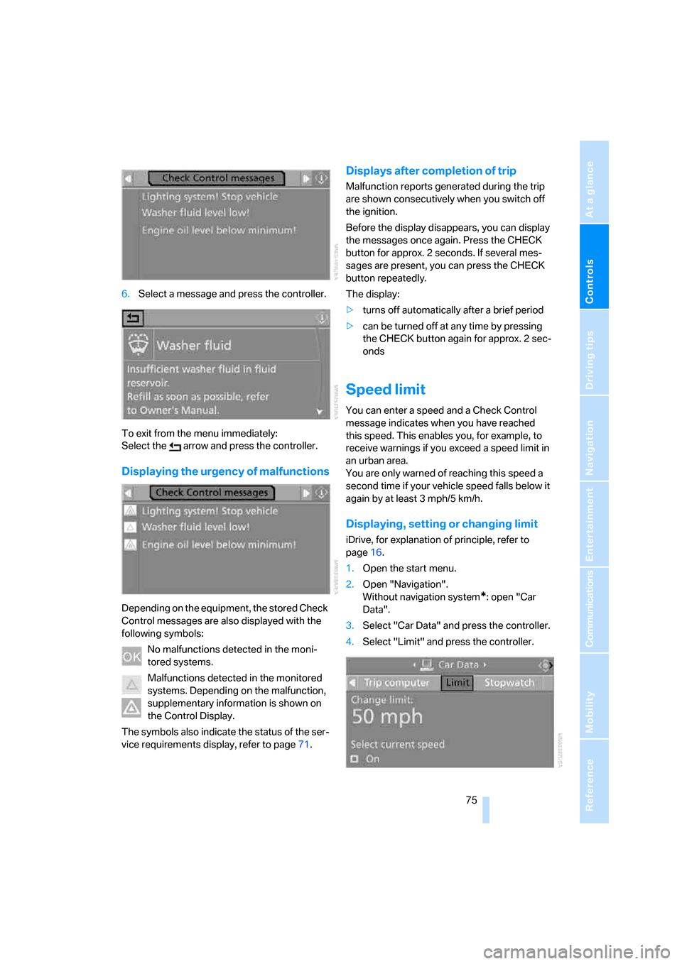
6.Select a message and press the controller.
To exit from the menu immediately:
Select the arrow and press the controller.
Displaying the urgency of malfunctions
Depending on the equipment, the stored Check
Control messages are also displayed with the
following symbols:
No malfunctions detected in the moni-
tored systems.
Malfunctions detected in the monitored
systems. Depending on the malfunction,
supplementary information is shown on
the Control Display.
The symbols also indicate the status of the ser-
vice requirements display, refer to page71.
Displays after completion of trip
Malfunction reports generated during the trip
are shown consecutively when you switch off
the ignition.
Before the display disappears, you can display
the messages once again. Press the CHECK
button for approx. 2 seconds. If several mes-
sages are present, you can press the CHECK
button repeatedly.
The display:
>turns off automatically after a brief period
>can be turned off at any time by pressing
the CHECK button again for approx. 2 sec-
onds
Speed limit
You can enter a speed and a Check Control
message indicates when you have reached
this speed. This enables you, for example, to
receive warnings if you exceed a speed limit in
an urban area.
You are only warned of reaching this speed a
second time if your vehicle speed falls below it
again by at least 3 mph/5 km/h.
Displaying, setting or changing limit
iDrive, for explanation of principle, refer to
page16.
1.Open the start menu.
2.Open "Navigation".
Without navigation system
*: open "Car
Data".
3.Select "Car Data" and press the controller.
4.Select "Limit" and press the controller.
Page 78 of 256
Everything under control
76 5.Select the speed value and press the con-
troller.
6.Turn the controller to set the limit. If neces-
sary, hold it against a slight resistance to
enter a greater difference.
7.Press the controller to apply the setting.
The limit is automatically switched on.
Applying your current speed as limit
Select "Select current speed" and press the
controller. The system applies your current
speed as the limit.
Activating limit
Select "On" and press the controller.
The limit is automatically switched on.
Stopwatch
iDrive, for explanation of principle, refer to
page16.
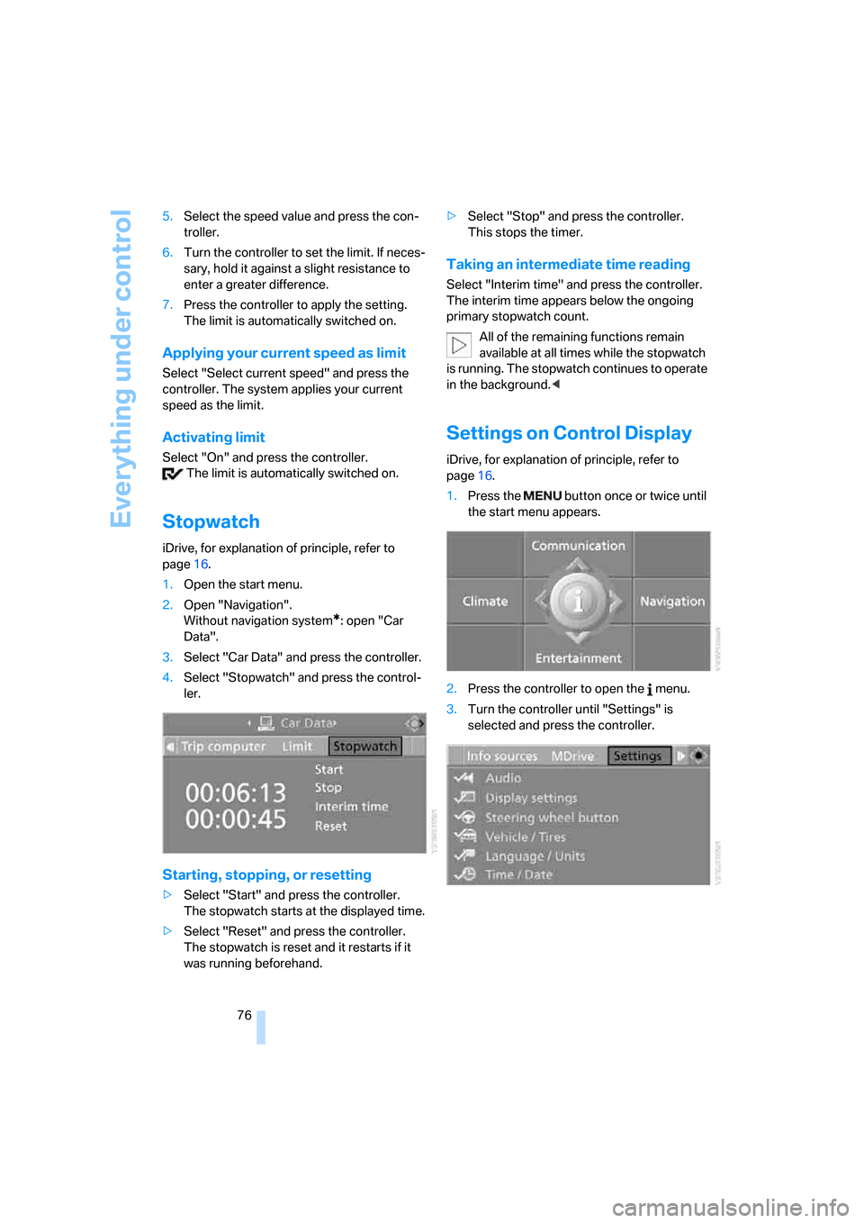
1.Open the start menu.
2.Open "Navigation".
Without navigation system
*: open "Car
Data".
3.Select "Car Data" and press the controller.
4.Select "Stopwatch" and press the control-
ler.
Starting, stopping, or resetting
>Select "Start" and press the controller.
The stopwatch starts at the displayed time.
>Select "Reset" and press the controller.
The stopwatch is reset and it restarts if it
was running beforehand.>Select "Stop" and press the controller.
This stops the timer.
Taking an intermediate time reading
Select "Interim time" and press the controller.
The interim time appears below the ongoing
primary stopwatch count.
All of the remaining functions remain
available at all times while the stopwatch
is running. The stopwatch continues to operate
in the background.<
Settings on Control Display
iDrive, for explanation of principle, refer to
page16.
1.Press the button once or twice until
the start menu appears.
2.Press the controller to open the menu.
3.Turn the controller until "Settings" is
selected and press the controller.
Page 83 of 256
Controls
81Reference
At a glance
Driving tips
Communications
Navigation
Entertainment
Mobility
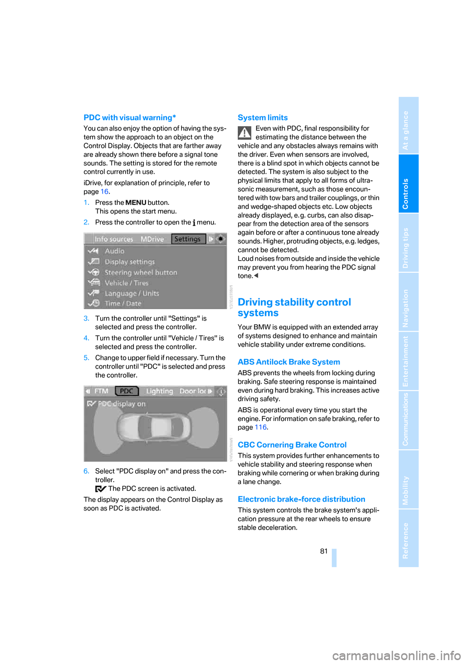
PDC with visual warning*
You can also enjoy the option of having the sys-
tem show the approach to an object on the
Control Display. Objects that are farther away
are already shown there before a signal tone
sounds. The setting is stored for the remote
control currently in use.
iDrive, for explanation of principle, refer to
page16.
1.Press the button.
This opens the start menu.
2.Press the controller to open the menu.
3.Turn the controller until "Settings" is
selected and press the controller.
4.Turn the controller until "Vehicle / Tires" is
selected and press the controller.
5.Change to upper field if necessary. Turn the
controller until "PDC" is selected and press
the controller.
6.Select "PDC display on" and press the con-
troller.
The PDC screen is activated.
The display appears on the Control Display as
soon as PDC is activated.
System limits
Even with PDC, final responsibility for
estimating the distance between the
vehicle and any obstacles always remains with
the driver. Even when sensors are involved,
there is a blind spot in which objects cannot be
detected. The system is also subject to the
physical limits that apply to all forms of ultra-
sonic measurement, such as those encoun-
tered with tow bars and trailer couplings, or thin
and wedge-shaped objects etc. Low objects
already displayed, e. g. curbs, can also disap-
pear from the detection area of the sensors
again before or after a continuous tone already
sounds. Higher, protruding objects, e.g. ledges,
cannot be detected.
Loud noises from outside and inside the vehicle
may prevent you from hearing the PDC signal
tone.<
Driving stability control
systems
Your BMW is equipped with an extended array
of systems designed to enhance and maintain
vehicle stability under extreme conditions.
ABS Antilock Brake System
ABS prevents the wheels from locking during
braking. Safe steering response is maintained
even during hard braking. This increases active
driving safety.
ABS is operational every time you start the
engine. For information on safe braking, refer to
page116.
CBC Cornering Brake Control
This system provides further enhancements to
vehicle stability and steering response when
braking while cornering or when braking during
a lane change.
Electronic brake-force distribution
This system controls the brake system's appli-
cation pressure at the rear wheels to ensure
stable deceleration.
Page 85 of 256
Controls
83Reference
At a glance
Driving tips
Communications
Navigation
Entertainment
Mobility
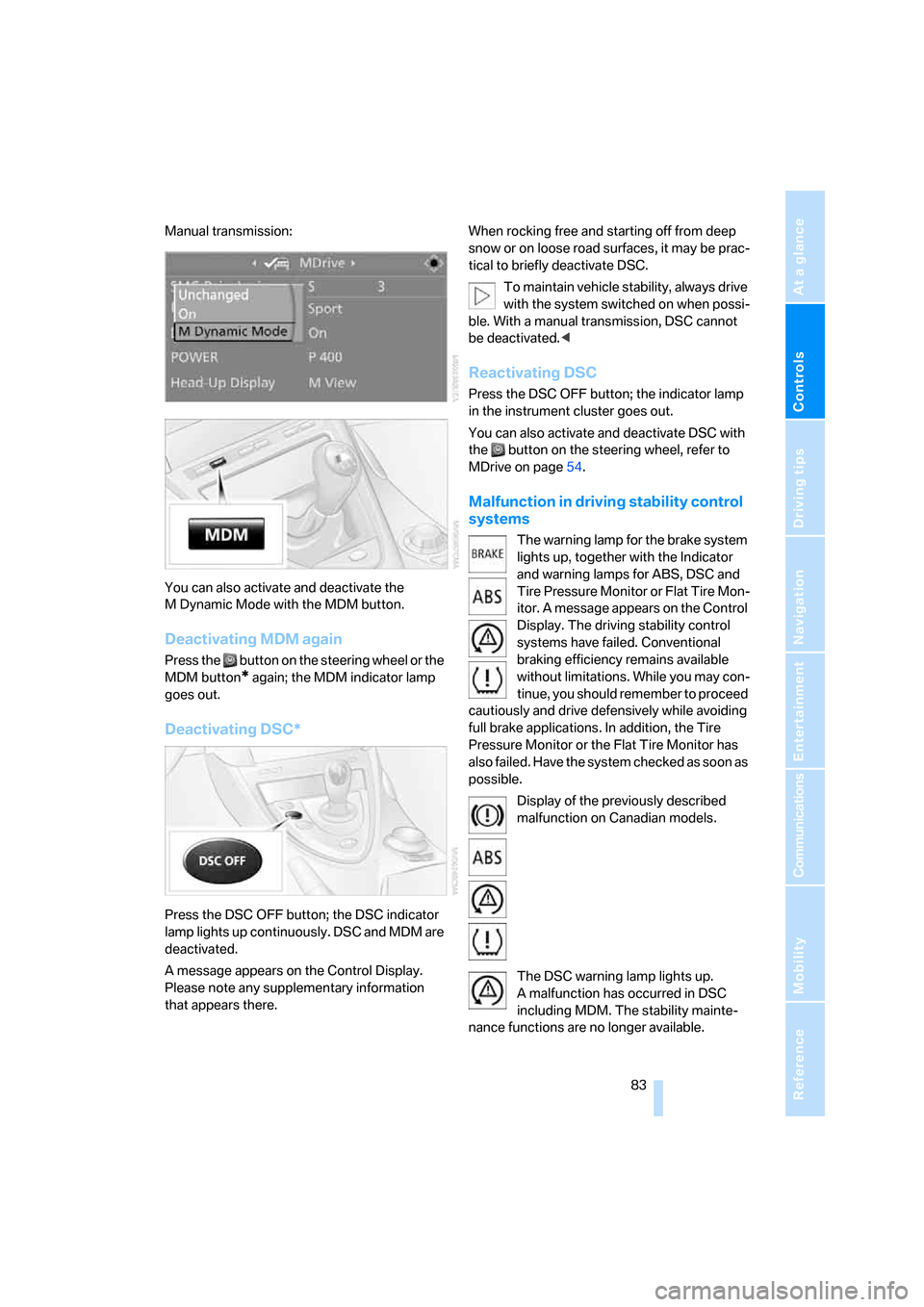
Manual transmission:
You can also activate and deactivate the
M Dynamic Mode with the MDM button.
Deactivating MDM again
Press the button on the steering wheel or the
MDM button
* again; the MDM indicator lamp
goes out.
Deactivating DSC*
Press the DSC OFF button; the DSC indicator
lamp lights up continuously. DSC and MDM are
deactivated.
A message appears on the Control Display.
Please note any supplementary information
that appears there.When rocking free and starting off from deep
snow or on loose road surfaces, it may be prac-
tical to briefly deactivate DSC.
To maintain vehicle stability, always drive
with the system switched on when possi-
ble. With a manual transmission, DSC cannot
be deactivated.<
Reactivating DSC
Press the DSC OFF button; the indicator lamp
in the instrument cluster goes out.
You can also activate and deactivate DSC with
the button on the steering wheel, refer to
MDrive on page54.
Malfunction in driving stability control
systems
The warning lamp for the brake system
lights up, together with the Indicator
and warning lamps for ABS, DSC and
Tire Pressure Monitor or Flat Tire Mon-
itor. A message appears on the Control
Display. The driving stability control
systems have failed. Conventional
braking efficiency remains available
without limitations. While you may con-
tinue, you should remember to proceed
cautiously and drive defensively while avoiding
full brake applications. In addition, the Tire
Pressure Monitor or the Flat Tire Monitor has
also failed. Have the system checked as soon as
possible.
Display of the previously described
malfunction on Canadian models.
The DSC warning lamp lights up.
A malfunction has occurred in DSC
including MDM. The stability mainte-
nance functions are no longer available.
Page 87 of 256
Controls
85Reference
At a glance
Driving tips
Communications
Navigation
Entertainment
Mobility
change. This change is detected and signaled
as a flat tire.
Functional requirement
To ensure the reliable signaling of a flat tire, the
system must be initialized at the correct tire
inflation pressure.
The initialization must be repeated after
every correction of the tire inflation pres-
sure and after every tire or wheel change.<
System limits
The Flat Tire Monitor cannot indicate
sudden severe tire damage caused by
outside factors and does not detect a natural,
even pressure drop in all four tires.<
In the following situations, the system could be
delayed or malfunction:
>System has not been initialized
>Driving on snow-covered or slippery roads
>Sporty driving style: slip in the drive wheels,
high lateral acceleration
>Driving with snow chains
*
Initializing system
The initialization finishes during driving,
which can be interrupted at any time.
When driving resumes, the initialization is auto-
matically continued.
Do not initialize the system when driving with
snow chains
*.<
With Sequential Manual Transmission via the
button in the center console:
1.Start the engine, but do not start driving.
2.Press the button at least 4 seconds, how-
ever not longer than 2 minutes. After
releasing the button, the warning lamp in
the instrument cluster lights up yellow for a
few seconds. Warning lamp, refer to Indica-
tion of a flat tire. The message "Initializing
FTM..." appears on the Control Display for a
few seconds.3.Start to drive. The initialization finishes dur-
ing driving without feedback.
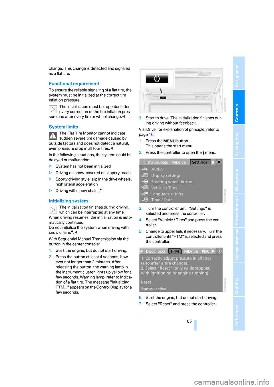
Via iDrive, for explanation of principle, refer to
page16:
1.Press the button.
This opens the start menu.
2.Press the controller to open the menu.
3.Turn the controller until "Settings" is
selected and press the controller.
4.Select "Vehicle / Tires" and press the con-
troller.
5.Change to upper field if necessary. Turn the
controller until "FTM" is selected and press
the controller.
6.Start the engine, but do not start driving.
7.Select "Reset" and press the controller.
Page 89 of 256
Controls
87Reference
At a glance
Driving tips
Communications
Navigation
Entertainment
Mobility
All wheels are yellow
Flat tire or a major drop in inflation pressure in
several tires. A message appears on the Control
Display.
Gray
The system cannot detect a flat tire.
Reasons for this can be:
>TPM is being reset
>Temporary interference due to systems or
devices which use the same radio fre-
quency
>Malfunction
Resetting system
Reset the system again after each correc-
tion of the tire inflation pressure and after
every tire or wheel change.<
Resetting finishes during driving, which can be
interrupted at any time. When driving resumes,
resetting is continued automatically.
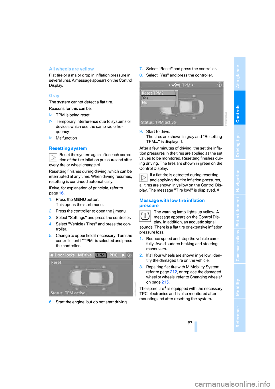
iDrive, for explanation of principle, refer to
page16.
1.Press the button.
This opens the start menu.
2.Press the controller to open the menu.
3.Select "Settings" and press the controller.
4.Select "Vehicle / Tires" and press the con-
troller.
5.Change to upper field if necessary. Turn the
controller until "TPM" is selected and press
the controller.
6.Start the engine, but do not start driving.7.Select "Reset" and press the controller.
8.Select "Yes" and press the controller.
9.Start to drive.
The tires are shown in gray and "Resetting
TPM..." is displayed.
After a few minutes of driving, the set tire infla-
tion pressures in the tires are applied as the set
values to be monitored. Resetting finishes dur-
ing driving. The tires are shown in green on the
Control Display.
If a flat tire is detected during resetting
and applying the tire inflation pressures,
all tires are shown in yellow on the Control Dis-
play. The message "Tire low!" is displayed.<
Message with low tire inflation
pressure
The warning lamp lights up yellow. A
message appears on the Control Dis-
play. In addition, an acoustic signal
sounds. There is a flat tire or extensive inflation
pressure loss.
1.Reduce speed and stop the vehicle care-
fully. Avoid sudden braking and steering
maneuvers.
2.If all four wheels are shown in yellow, iden-
tify the damaged tire on the vehicle.
3.Repairing flat tire with M Mobility System,
refer to page212, or replace the damaged
wheel or wheels, refer to Changing wheels*
on page215.
The spare tire
* is equipped with the necessary
TPC electronics and is also monitored after
mounting and after resetting the system.
Page 91 of 256
Controls
89Reference
At a glance
Driving tips
Communications
Navigation
Entertainment
Mobility
Airbags
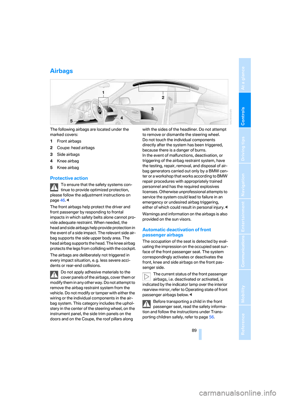
The following airbags are located under the
marked covers:
1Front airbags
2Coupe: head airbags
3Side airbags
4Knee airbag
5Knee airbag
Protective action
To ensure that the safety systems con-
tinue to provide optimized protection,
please follow the adjustment instructions on
page46.<
The front airbags help protect the driver and
front passenger by responding to frontal
impacts in which safety belts alone cannot pro-
vide adequate restraint. When needed, the
head and side airbags help provide protection in
the event of a side impact. The relevant side air-
bag supports the side upper body area. The
head airbag supports the head. The knee airbag
protects the legs from colliding with the cockpit.
The airbags are deliberately not triggered in
every impact situation, e. g. less severe acci-
dents or rear-end collisions.
Do not apply adhesive materials to the
cover panels of the airbags, cover them or
modify them in any other way. Do not attempt to
remove the airbag restraint system from the
vehicle. Do not modify or tamper with either the
wiring or the individual components in the air-
bag system. This category includes the uphol-
stery in the center of the steering wheel, on the
instrument panel, the side trim panels on the
doors and on the Coupe, the roof pillars along with the sides of the headliner. Do not attempt
to remove or dismantle the steering wheel.
Do not touch the individual components
directly after the system has been triggered,
because there is a danger of burns.
In the event of malfunctions, deactivation, or
triggering of the airbag restraint system, have
the testing, repair, removal, and disposal of air-
bag generators carried out only by a BMW cen-
ter or a workshop that works according to BMW
repair procedures with appropriately trained
personnel and has the required explosives
licenses. Otherwise unprofessional attempts to
service the system could lead to failure in an
emergency or undesired airbag triggering,
either of which could result in personal injury.<
Warnings and information on the airbags is also
provided on the sun visors.
Automatic deactivation of front
passenger airbags
The occupation of the seat is detected by eval-
uating the impression on the occupied seat sur-
face of the front passenger seat. The system
correspondingly activates or deactivates the
front, knee and side airbags on the front pas-
senger side.
The current status of the front passenger
airbags, i.e. deactivated or activated, is
indicated by the indicator lamp over the interior
rearview mirror, refer to Operating state of front
passenger airbags below.<
Before transporting a child in the front
passenger seat, read the safety informa-
tion and follow the instructions under Trans-
porting children safely, refer to page56.
Page 93 of 256
Controls
91Reference
At a glance
Driving tips
Communications
Navigation
Entertainment
Mobility
Convertible: rollover
protection system
The rollover protection system is automatically
activated in the event of an accident or a critical
driving situation, extreme inclination on the lon-
gitudinal axis, or loss of ground contact. The
rollover bars located behind the rear head
restraints are deployed within fractions of a sec-
ond.
As a supplement to the rollover bar integrated
into the windshield frame, the rollover protec-
tion system ensures that all vehicle occupants
have the necessary headroom.
Always keep the path of movement of the
rollover protection system clear.
In less severe accidents, you are protected by
the fastened safety belt and, depending on the
severity of the accident, the belt tensioner and
the multistage airbag restraint system.<
Lowering
If the rollover protection system experienced no
impact after automatic activation, then it can be
lowered again. No tools are necessary for this
purpose.
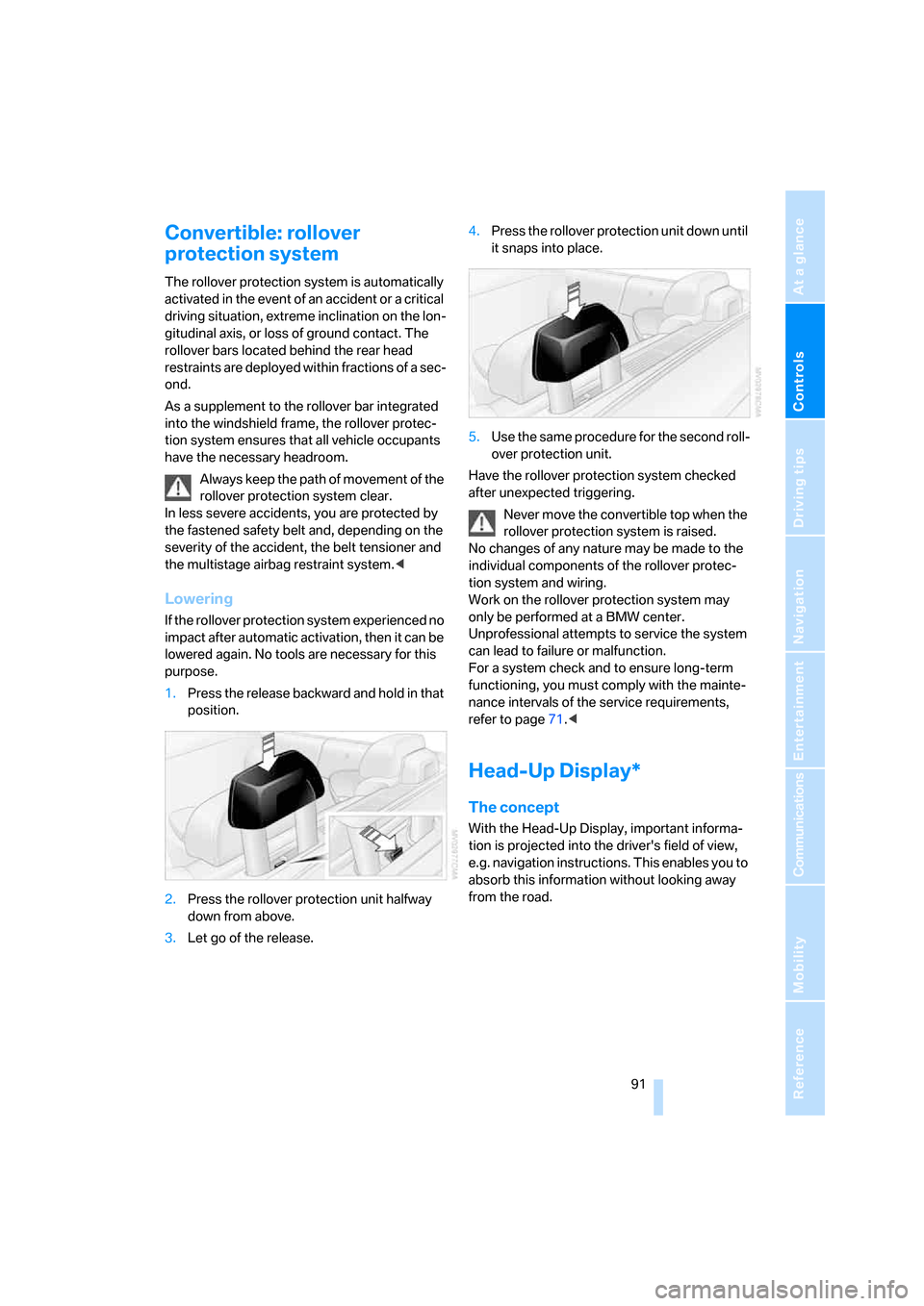
1.Press the release backward and hold in that
position.
2.Press the rollover protection unit halfway
down from above.
3.Let go of the release.4.Press the rollover protection unit down until
it snaps into place.
5.Use the same procedure for the second roll-
over protection unit.
Have the rollover protection system checked
after unexpected triggering.
Never move the convertible top when the
rollover protection system is raised.
No changes of any nature may be made to the
individual components of the rollover protec-
tion system and wiring.
Work on the rollover protection system may
only be performed at a BMW center.
Unprofessional attempts to service the system
can lead to failure or malfunction.
For a system check and to ensure long-term
functioning, you must comply with the mainte-
nance intervals of the service requirements,
refer to page71.<
Head-Up Display*
The concept
With the Head-Up Display, important informa-
tion is projected into the driver's field of view,
e.g. navigation instructions. This enables you to
absorb this information without looking away
from the road.