BMW M6 CONVERTIBLE 2012 Owners Manual
Manufacturer: BMW, Model Year: 2012, Model line: M6 CONVERTIBLE, Model: BMW M6 CONVERTIBLE 2012Pages: 297, PDF Size: 12.09 MB
Page 101 of 297
▷A wheel without TPM electronics is fitted:
have the service center check it if necessary.▷Malfunction: have the system checked by
your service center.▷TPM could not be fully reset. Reset the sys‐
tem again.▷Disturbance by systems or devices with the
same radio frequency: after leaving the area
of the disturbance, the system automatically
becomes active again.
Declaration according to NHTSA/
FMVSS 138 Tire Pressure Monitoring
System
Each tire, including the spare (if provided)
should be checked monthly when cold and in‐
flated to the inflation pressure recommended by
the vehicle manufacturer on the vehicle placard
or tire inflation pressure label. (If your vehicle has
tires of a different size than the size indicated on
the vehicle placard or tire inflation pressure la‐
bel, you should determine the proper tire infla‐
tion pressure for those tires.) As an added safety
feature, your vehicle has been equipped with a
tire pressure monitoring system (TPMS) that il‐
luminates a low tire pressure telltale when one
or more of your tires is significantly under-in‐
flated. Accordingly, when the low tire pressure
telltale illuminates, you should stop and check
your tires as soon as possible, and inflate them
to the proper pressure. Driving on a significantly
under-inflated tire causes the tire to overheat
and can lead to tire failure. Under-inflation also
reduces fuel efficiency and tire tread life, and
may affect the vehicle's handling and stopping
ability. Please note that the TPMS is not a sub‐
stitute for proper tire maintenance, and it is the
driver's responsibility to maintain correct tire
pressure, even if under-inflation has not reached
the level to trigger illumination of the TPMS low
tire pressure telltale. Your vehicle has also been
equipped with a TPMS malfunction indicator to
indicate when the system is not operating prop‐
erly. The TPMS malfunction indicator is com‐
bined with the low tire pressure telltale. When
the system detects a malfunction, the telltale will
flash for approximately one minute and then re‐
main continuously illuminated. This sequence
will continue upon subsequent vehicle start-ups
as long as the malfunction exists. When the mal‐
function indicator is illuminated, the system may
not be able to detect or signal low tire pressure
as intended. TPMS malfunctions may occur for
a variety of reasons, including the installation of
replacement or alternate tires or wheels on the
vehicle that prevent the TPMS from functioning
properly. Always check the TPMS malfunction
telltale after replacing one or more tires or
wheels on your vehicle to ensure that the re‐
placement or alternate tires and wheels allow
the TPMS to continue to function properly.
FTM Flat Tire Monitor
The concept
The system does not measure the actual infla‐
tion pressure in the tires.
It detects a pressure loss in a tire by comparing
the rotational speeds of the individual wheels
while moving.
In the event of a pressure loss, the diameter and
therefore the rotational speed of the corre‐
sponding wheel change. This is detected and
reported as a flat tire.
Functional requirements
The system must have been initialized when the
tire inflation pressure was correct; otherwise,
reliable signaling of a flat tire is not ensured. In‐
itialize the system after each correction of the
tire inflation pressure and after every tire or
wheel change.
System limits Sudden tire damage
Sudden serious tire damage caused by
external influences cannot be indicated in ad‐
vance.◀Seite 101SafetyControls101
Online Edition for Part no. 01 40 2 900 735 - 03 12 490
Page 102 of 297
A natural, even pressure loss in all four tires can‐
not be detected. Therefore, check the tire infla‐
tion pressure regularly.
The system could be delayed or malfunction in
the following situations:▷When the system has not been initialized.▷When driving on a snowy or slippery road
surface.▷Sporty driving style: slip in the drive wheels,
high lateral acceleration.▷When driving with snow chains.
Status display
The current status of the Flat Tire Monitor can
be displayed on the Control Display, e.g.,
whether or not the FTM is active.
1."Vehicle Info"2."Vehicle status"3. "Flat Tire Monitor"
The status is displayed.
Initialization
The initialization process adopts the set inflation
tire pressures as reference values for the detec‐
tion of a flat tire. Initialization is started by con‐
firming the inflation pressures.
Do not initialize the system when driving with
snow chains.
1."Vehicle Info"2."Vehicle status"3. "Reset"4.Start the engine - do not drive away.5.Start the initialization with "Reset".6.Drive away.
The initialization is completed while driving,
which can be interrupted at any time.
The initialization automatically continues when
driving resumes.
Indication of a flat tire
The yellow warning lamp lights up. A
Check Control message is displayed.
There is a flat tire or a major loss in tire
inflation pressure.1.Reduce your speed and stop cautiously.
Avoid sudden braking and steering maneu‐
vers.2.Identify the damaged wheel. Do so by
checking the tire inflation pressure using the
Mobility System. If the tire inflation pressure
in all tires is correct, the Flat Tire Monitor
may not have been initialized. In this case,
initialize the system.3.Repair flat tire with the Mobility System, re‐
fer to page 246, or replace the damaged
wheel.
Lane departure warning
The concept
Starting at a specific speed, this system alerts
you when the vehicle on streets with lane mark‐
ings is about to leave the lane. Depending on the
country-specific version of the vehicle, the
speed is between 35 mph/55 km/h and
45 mph/70 km/h. When switching on the system
below this speed, a message appears in the in‐
strument cluster.
The steering wheel begins vibrating gently in the
event of warnings. The time of the warning may
vary depending on the current driving situation.
The system does not provide a warning if the
turn signal is set before leaving the lane.
Seite 102ControlsSafety102
Online Edition for Part no. 01 40 2 900 735 - 03 12 490
Page 103 of 297
Switching on/off
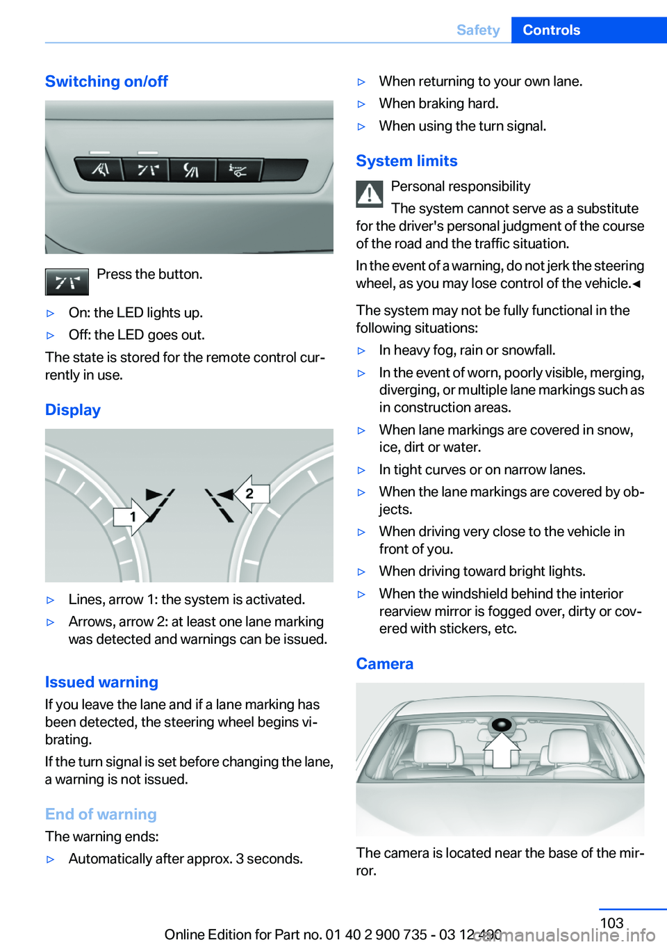
Press the button.
▷On: the LED lights up.▷Off: the LED goes out.
The state is stored for the remote control cur‐
rently in use.
Display
▷Lines, arrow 1: the system is activated.▷Arrows, arrow 2: at least one lane marking
was detected and warnings can be issued.
Issued warning
If you leave the lane and if a lane marking has
been detected, the steering wheel begins vi‐
brating.
If the turn signal is set before changing the lane,
a warning is not issued.
End of warning
The warning ends:
▷Automatically after approx. 3 seconds.▷When returning to your own lane.▷When braking hard.▷When using the turn signal.
System limits
Personal responsibility
The system cannot serve as a substitute
for the driver's personal judgment of the course
of the road and the traffic situation.
In the event of a warning, do not jerk the steering
wheel, as you may lose control of the vehicle.◀
The system may not be fully functional in the
following situations:
▷In heavy fog, rain or snowfall.▷In the event of worn, poorly visible, merging,
diverging, or multiple lane markings such as
in construction areas.▷When lane markings are covered in snow,
ice, dirt or water.▷In tight curves or on narrow lanes.▷When the lane markings are covered by ob‐
jects.▷When driving very close to the vehicle in
front of you.▷When driving toward bright lights.▷When the windshield behind the interior
rearview mirror is fogged over, dirty or cov‐
ered with stickers, etc.
Camera
The camera is located near the base of the mir‐
ror.
Seite 103SafetyControls103
Online Edition for Part no. 01 40 2 900 735 - 03 12 490
Page 104 of 297
Keep windshield clean and clear in the area in
front of the interior rear view mirror.
Active Blind Spot Detection
The concept
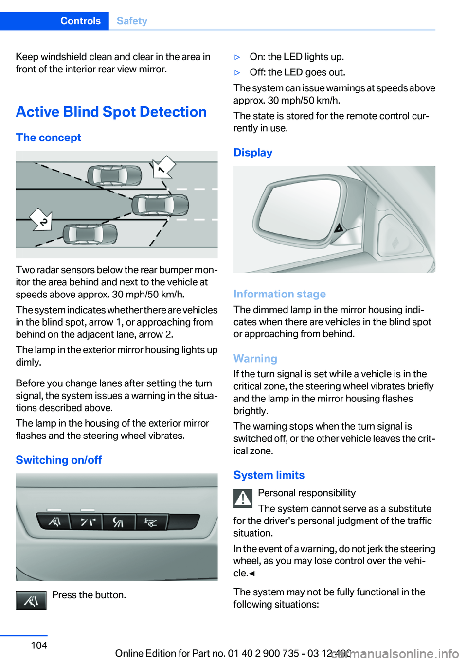
Two radar sensors below the rear bumper mon‐
itor the area behind and next to the vehicle at
speeds above approx. 30 mph/50 km/h.
The system indicates whether there are vehicles
in the blind spot, arrow 1, or approaching from
behind on the adjacent lane, arrow 2.
The lamp in the exterior mirror housing lights up
dimly.
Before you change lanes after setting the turn
signal, the system issues a warning in the situa‐
tions described above.
The lamp in the housing of the exterior mirror
flashes and the steering wheel vibrates.
Switching on/off
Press the button.
▷On: the LED lights up.▷Off: the LED goes out.
The system can issue warnings at speeds above
approx. 30 mph/50 km/h.
The state is stored for the remote control cur‐
rently in use.
Display
Information stage
The dimmed lamp in the mirror housing indi‐
cates when there are vehicles in the blind spot
or approaching from behind.
Warning
If the turn signal is set while a vehicle is in the
critical zone, the steering wheel vibrates briefly
and the lamp in the mirror housing flashes
brightly.
The warning stops when the turn signal is
switched off, or the other vehicle leaves the crit‐
ical zone.
System limits Personal responsibility
The system cannot serve as a substitute
for the driver's personal judgment of the traffic
situation.
In the event of a warning, do not jerk the steering
wheel, as you may lose control over the vehi‐
cle.◀
The system may not be fully functional in the
following situations:
Seite 104ControlsSafety104
Online Edition for Part no. 01 40 2 900 735 - 03 12 490
Page 105 of 297
▷When a vehicle is approaching at a speed
much faster than your own.▷In heavy fog, rain or snowfall.▷In tight curves or on narrow lanes.
Radar sensors
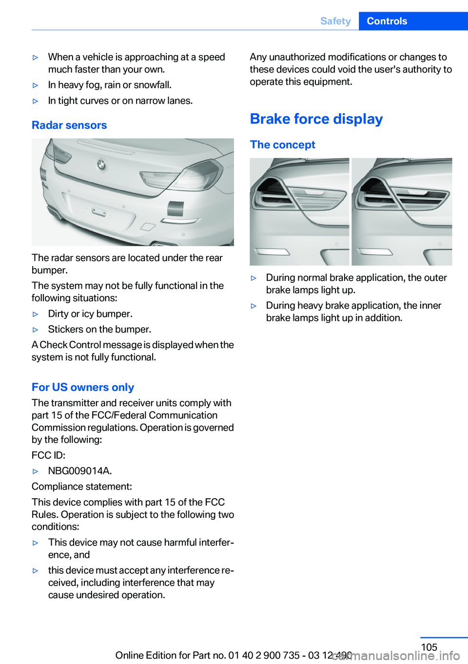
The radar sensors are located under the rear
bumper.
The system may not be fully functional in the
following situations:
▷Dirty or icy bumper.▷Stickers on the bumper.
A Check Control message is displayed when the
system is not fully functional.
For US owners only
The transmitter and receiver units comply with
part 15 of the FCC/Federal Communication
Commission regulations. Operation is governed
by the following:
FCC ID:
▷NBG009014A.
Compliance statement:
This device complies with part 15 of the FCC
Rules. Operation is subject to the following two
conditions:
▷This device may not cause harmful interfer‐
ence, and▷this device must accept any interference re‐
ceived, including interference that may
cause undesired operation.Any unauthorized modifications or changes to
these devices could void the user's authority to
operate this equipment.
Brake force display
The concept▷During normal brake application, the outer
brake lamps light up.▷During heavy brake application, the inner
brake lamps light up in addition.Seite 105SafetyControls105
Online Edition for Part no. 01 40 2 900 735 - 03 12 490
Page 106 of 297
Driving stability control systemsVehicle equipment
All standard, country-specific and optional
equipment that is offered in the model series is
described in this chapter. Therefore, equipment
is also described that is not available in a vehicle,
e. g., because of the selected optional equip‐
ment or country variant. This also applies for
safety-related functions and systems.
Antilock Brake System ABS
ABS prevents locking of the wheels during brak‐
ing.
The vehicle remains steerable even during full
brake applications, thus increasing active
safety.
ABS is operational every time you start the en‐
gine.
Brake assistant
When you apply the brakes rapidly, this system
automatically produces the maximum braking
force boost. It thus helps to achieve the shortest
possible braking distance during full braking.
This system utilizes all of the benefits provided
by ABS.
Do not reduce the pressure on the brake pedal
for the duration of the full braking.
Drive-off assistant
This system supports driving away on gradients.
The parking brake is not required.1.Hold the vehicle in place with the foot brake.2.Release the foot brake and drive away with‐
out delay.After the foot brake is released, the vehicle is
held in place for approx. 2 seconds.
Depending on the vehicle load, the vehicle may
roll back slightly.
Driving off without delay
After releasing the foot brake, start driving
without delay, since the drive-off assistant will
not hold the vehicle in place for more than ap‐
prox. 2 seconds and the vehicle will begin rolling
back.◀
DSC Dynamic Stability
Control
The concept
DSC prevents traction loss in the driving wheels
when driving away and accelerating.
DSC also recognizes unstable vehicle condi‐
tions, such as fishtailing or nose-diving. Subject
to physical limits, DSC helps to keep the vehicle
on a steady course by reducing engine speed
and by applying brakes at individual wheels.
Adjust your driving style to the situation
An appropriate driving style is always the
responsibility of the driver.
The laws of physics cannot be repealed, even
with DSC.
Therefore, do not reduce the additional safety
margin by driving in a risky manner.◀
Indicator/warning lamps The indicator lamp flashes: DSC con‐
trols the drive forces and brake forces.
The indicator lamp lights up: DSC has
failed.Seite 106ControlsDriving stability control systems106
Online Edition for Part no. 01 40 2 900 735 - 03 12 490
Page 107 of 297
M Dynamic Mode MDM
M Dynamic Mode makes it possible to drive on
a dry roadway with high longitudinal and trans‐
verse acceleration but with limited driving sta‐
bility.
Only in the absolute limit area does the system
intervene for stabilization by reducing the en‐
gine power and by braking interventions on the
wheels. In this driving condition, additional
steering corrections may be necessary.
Limited stabilizing interventions
When M Dynamic Mode is activated, sta‐
bilizing interventions are carried out only to a re‐
duced extent. You must react yourself; other‐
wise, there is the danger of an accident
occurring.◀
To increase vehicle stability, activate DSC again
as soon as possible.
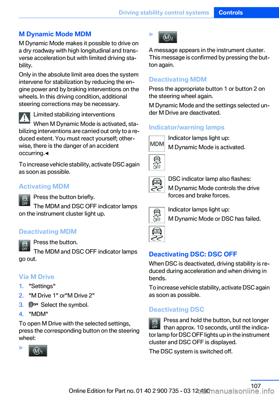
Activating MDM Press the button briefly.
The MDM and DSC OFF indicator lamps
on the instrument cluster light up.
Deactivating MDM Press the button.
The MDM and DSC OFF indicator lamps
go out.
Via M Drive1."Settings"2."M Drive 1" or"M Drive 2"3. Select the symbol.4."MDM"
To open M Drive with the selected settings,
press the corresponding button on the steering
wheel:
▷▷
A message appears in the instrument cluster.
This message is confirmed by pressing the but‐
ton again.
Deactivating MDM
Press the appropriate button 1 or button 2 on
the steering wheel again.
M Dynamic Mode and the settings selected un‐
der M Drive are deactivated.
Indicator/warning lamps Indicator lamps light up:
M Dynamic Mode is activated.
DSC indicator lamp also flashes:
M Dynamic Mode controls the drive
forces and brake forces.
Indicator lamps light up:
M Dynamic Mode or DSC has failed.
Deactivating DSC: DSC OFF
When DSC is deactivated, driving stability is re‐
duced during acceleration and when driving in
bends.
To increase vehicle stability, activate DSC again
as soon as possible.
Deactivating DSC Press and hold the button, but not longer
than approx. 10 seconds, until the indica‐
tor lamp for DSC OFF lights up in the instrument
cluster and DSC OFF is displayed.
The DSC system is switched off.
Seite 107Driving stability control systemsControls107
Online Edition for Part no. 01 40 2 900 735 - 03 12 490
Page 108 of 297
Activating DSCPress the button.
DSC OFF and the DSC OFF indicator lamp
go out.
Via M Drive1."Settings"2."M Drive 1" or"M Drive 2"3. Select the symbol.4."DSC OFF"
To open M Drive with the selected settings,
press the corresponding button on the steering
wheel:
▷▷
A message appears in the instrument cluster.
This message is confirmed by pressing the but‐
ton again.
Indicator/warning lamps
When DSC is deactivated, DSC OFF is dis‐
played in the instrument cluster.
The indicator lamp lights up: DSC is de‐
activated.
Hill Start Assistant
The Hill Start Assistant provides assistance with
starting off on a hill, Drive-off assistant, refer to
page 106.
Active M differential
The concept
The active M differential assures continuously
variable locking of the rear axle differential de‐
pending on the driving situation. This prevents
individual rear wheels from spinning even when
DSC is switched off and in M Dynamic Mode, so
that optimum traction is always assured in all
driving situations.
The driver is responsible adapting his or her
driving behavior to the situation.
Electronic Damper Control
EDC
The concept
This system reduces undesirable vehicle mo‐
tion when using a dynamic driving style or trav‐
eling on uneven road surfaces.
The system enhances driving dynamics and
comfort as required for the road surface and
driving style.
Programs
Setting options for calibrating the shock absorb‐
ers:▷"Comfort": comfort-oriented.▷"Sport": balanced out.▷"Sport Plus": consistently sporty.
Selecting a channel
Via M Drive
1."Settings"2."M Drive 1" or"M Drive 2"3. Select the symbol.4.Select the desired channel.
When M Drive is active, setting is immedi‐
ately applied.
To activate M Drive with the selected settings,
press the corresponding button on the steering
wheel:
▷▷Seite 108ControlsDriving stability control systems108
Online Edition for Part no. 01 40 2 900 735 - 03 12 490
Page 109 of 297
Using the button
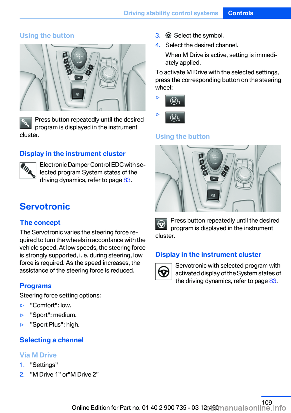
Press button repeatedly until the desired
program is displayed in the instrument
cluster.
Display in the instrument cluster Electronic Damper Control EDC with se‐
lected program System states of the
driving dynamics, refer to page 83.
Servotronic
The concept
The Servotronic varies the steering force re‐
quired to turn the wheels in accordance with the
vehicle speed. At low speeds, the steering force
is strongly supported, i. e. during steering, low
force is required. As the speed increases, the
assistance of the steering force is reduced.
Programs
Steering force setting options:
▷"Comfort": low.▷"Sport": medium.▷"Sport Plus": high.
Selecting a channel
Via M Drive
1."Settings"2."M Drive 1" or"M Drive 2"3. Select the symbol.4.Select the desired channel.
When M Drive is active, setting is immedi‐
ately applied.
To activate M Drive with the selected settings,
press the corresponding button on the steering
wheel:
▷▷
Using the button
Press button repeatedly until the desired
program is displayed in the instrument
cluster.
Display in the instrument cluster Servotronic with selected program with
activated display of the System states of
the driving dynamics, refer to page 83.
Seite 109Driving stability control systemsControls109
Online Edition for Part no. 01 40 2 900 735 - 03 12 490
Page 110 of 297
Driving comfortVehicle equipment
All standard, country-specific and optional
equipment that is offered in the model series is
described in this chapter. Therefore, equipment
is also described that is not available in a vehicle,
e. g., because of the selected optional equip‐
ment or country variant. This also applies for
safety-related functions and systems.
Cruise control
The concept
The system is functional at speeds beginning at
approx. 20 mph/30 km/h.
It maintains the speed that was set using the
control elements on the steering wheel.
The system brakes on downhill gradients if en‐
gine braking action is insufficient.
Unfavorable conditions
Do not use the system if unfavorable con‐
ditions make it impossible to drive at a constant
speed, for instance:▷On curvy roads.▷In heavy traffic.▷On slippery roads, in fog, snow or rain, or on
a loose road surface.
Otherwise, you could lose control of the vehicle
and cause an accident.◀
Controls
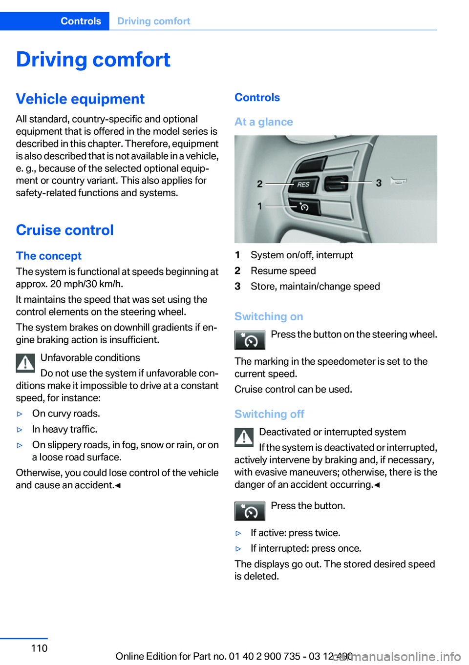
At a glance1System on/off, interrupt2Resume speed3Store, maintain/change speed
Switching on Press the button on the steering wheel.
The marking in the speedometer is set to the
current speed.
Cruise control can be used.
Switching off Deactivated or interrupted system
If the system is deactivated or interrupted,
actively intervene by braking and, if necessary,
with evasive maneuvers; otherwise, there is the
danger of an accident occurring.◀
Press the button.
▷If active: press twice.▷If interrupted: press once.
The displays go out. The stored desired speed
is deleted.
Seite 110ControlsDriving comfort110
Online Edition for Part no. 01 40 2 900 735 - 03 12 490