BMW M6 CONVERTIBLE 2012 Manual Online
Manufacturer: BMW, Model Year: 2012, Model line: M6 CONVERTIBLE, Model: BMW M6 CONVERTIBLE 2012Pages: 297, PDF Size: 12.09 MB
Page 81 of 297
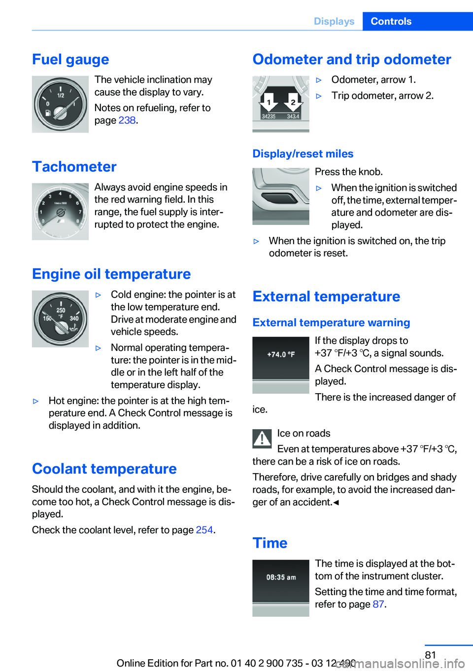
Fuel gaugeThe vehicle inclination may
cause the display to vary.
Notes on refueling, refer to
page 238.
Tachometer Always avoid engine speeds in
the red warning field. In this
range, the fuel supply is inter‐
rupted to protect the engine.
Engine oil temperature▷Cold engine: the pointer is at
the low temperature end.
Drive at moderate engine and
vehicle speeds.▷Normal operating tempera‐
ture: the pointer is in the mid‐
dle or in the left half of the
temperature display.▷Hot engine: the pointer is at the high tem‐
perature end. A Check Control message is
displayed in addition.
Coolant temperature
Should the coolant, and with it the engine, be‐
come too hot, a Check Control message is dis‐
played.
Check the coolant level, refer to page 254.
Odometer and trip odometer▷Odometer, arrow 1.▷Trip odometer, arrow 2.
Display/reset miles
Press the knob.
▷When the ignition is switched
off, the time, external temper‐
ature and odometer are dis‐
played.▷When the ignition is switched on, the trip
odometer is reset.
External temperature
External temperature warning If the display drops to
+37 ℉/+3 ℃, a signal sounds.
A Check Control message is dis‐
played.
There is the increased danger of
ice.
Ice on roads
Even at temperatures above +37 ℉/+3 ℃,
there can be a risk of ice on roads.
Therefore, drive carefully on bridges and shady
roads, for example, to avoid the increased dan‐
ger of an accident.◀
Time The time is displayed at the bot‐
tom of the instrument cluster.
Setting the time and time format,
refer to page 87.
Seite 81DisplaysControls81
Online Edition for Part no. 01 40 2 900 735 - 03 12 490
Page 82 of 297
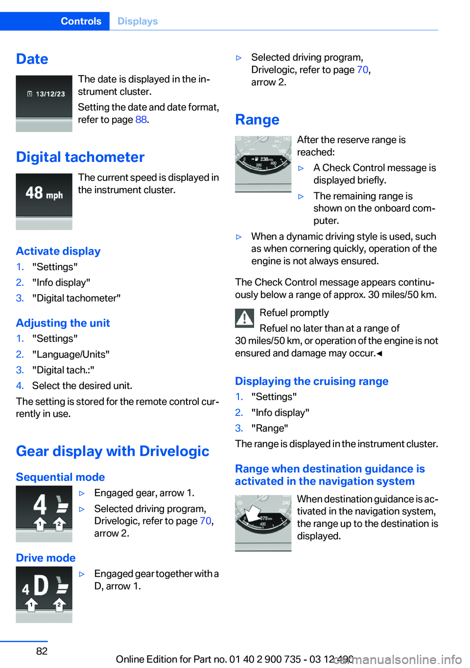
DateThe date is displayed in the in‐
strument cluster.
Setting the date and date format,
refer to page 88.
Digital tachometer The current speed is displayed in
the instrument cluster.
Activate display1."Settings"2."Info display"3."Digital tachometer"
Adjusting the unit
1."Settings"2."Language/Units"3."Digital tach.:"4.Select the desired unit.
The setting is stored for the remote control cur‐
rently in use.
Gear display with Drivelogic
Sequential mode
▷Engaged gear, arrow 1.▷Selected driving program,
Drivelogic, refer to page 70,
arrow 2.
Drive mode
▷Engaged gear together with a
D, arrow 1.▷Selected driving program,
Drivelogic, refer to page 70,
arrow 2.
Range
After the reserve range is
reached:
▷A Check Control message is
displayed briefly.▷The remaining range is
shown on the onboard com‐
puter.▷When a dynamic driving style is used, such
as when cornering quickly, operation of the
engine is not always ensured.
The Check Control message appears continu‐
ously below a range of approx. 30 miles/50 km.
Refuel promptly
Refuel no later than at a range of
30 miles/50 km, or operation of the engine is not
ensured and damage may occur.◀
Displaying the cruising range
1."Settings"2."Info display"3."Range"
The range is displayed in the instrument cluster.
Range when destination guidance is
activated in the navigation system
When destination guidance is ac‐
tivated in the navigation system,
the range up to the destination is
displayed.
Seite 82ControlsDisplays82
Online Edition for Part no. 01 40 2 900 735 - 03 12 490
Page 83 of 297
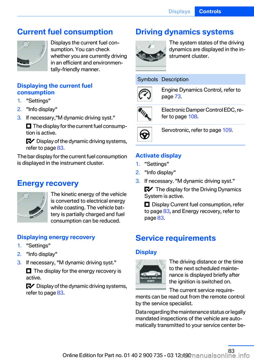
Current fuel consumptionDisplays the current fuel con‐
sumption. You can check
whether you are currently driving
in an efficient and environmen‐
tally-friendly manner.
Displaying the current fuel
consumption1."Settings"2."Info display"3.If necessary,"M dynamic driving syst."
The display for the current fuel consump‐
tion is active.
Display of the dynamic driving systems,
refer to page 83.
The bar display for the current fuel consumption
is displayed in the instrument cluster.
Energy recovery The kinetic energy of the vehicle
is converted to electrical energy
while coasting. The vehicle bat‐
tery is partially charged and fuel
consumption can be reduced.
Displaying energy recovery
1."Settings"2."Info display"3.If necessary, "M dynamic driving syst."
The display for the energy recovery is
active.
Display of the dynamic driving systems,
refer to page 83.
Driving dynamics systems
The system states of the driving
dynamics are displayed in the in‐
strument cluster.SymbolsDescriptionEngine Dynamics Control, refer to
page 73.Electronic Damper Control EDC, re‐
fer to page 108.Servotronic, refer to page 109.
Activate display
1."Settings"2."Info display"3.If necessary. "M dynamic driving syst."
The display for the Driving Dynamics
System is active.
Display Current fuel consumption, refer
to page 83, and Energy recovery, refer to
page 83.
Service requirements
Display The driving distance or the time
to the next scheduled mainte‐
nance is displayed briefly after
the ignition is switched on.
The current service require‐
ments can be read out from the remote control
by the service specialist.
Data regarding the maintenance status or legally
mandated inspections of the vehicle are auto‐
matically transmitted to your service center be‐
Seite 83DisplaysControls83
Online Edition for Part no. 01 40 2 900 735 - 03 12 490
Page 84 of 297
fore a service due date, Automatic Service Re‐
quest, refer to page 230.
Detailed information on service
requirements
More information on the scope of service re‐
quired can be displayed on the Control Display.1."Vehicle Info"2."Vehicle status"3. "Service required"
Required maintenance procedures and le‐
gally mandated inspections are displayed.4.Select an entry to call up detailed informa‐
tion.
Symbols
SymbolsDescriptionNo service is currently required.The deadline for service or a le‐
gally mandated inspection is
approaching.The service deadline has al‐
ready passed.
Entering appointment dates
Enter the dates for the required inspections.
Ensure that the vehicle date and time are set
correctly.
1."Vehicle Info"2."Vehicle status"3. "Service required"4."§ Vehicle inspection"5."Date:"6.Create the settings.7.Confirm.
The entered date is stored.Automatic Service Request
Data regarding the maintenance status or legally
mandated inspections of the vehicle are auto‐
matically transmitted to your service center be‐
fore a service due date.
You can check when your service center was
notified.1."Vehicle Info"2."Vehicle status"3.Open "Options".4."Last Service Request"
Selection lists in the
instrument cluster
The concept
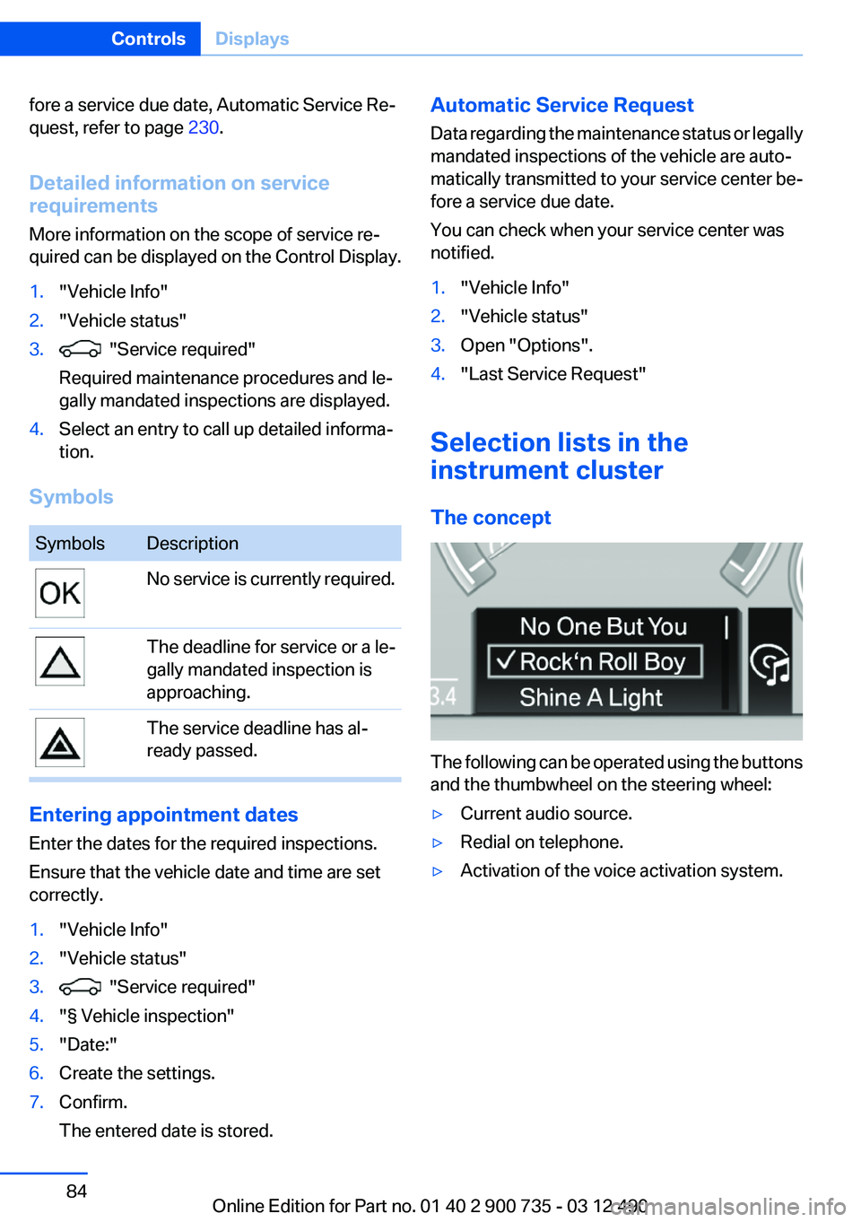
The following can be operated using the buttons
and the thumbwheel on the steering wheel:
▷Current audio source.▷Redial on telephone.▷Activation of the voice activation system.Seite 84ControlsDisplays84
Online Edition for Part no. 01 40 2 900 735 - 03 12 490
Page 85 of 297
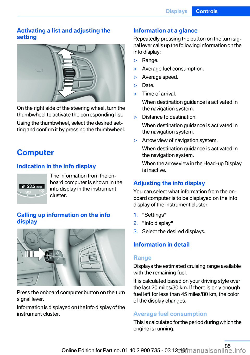
Activating a list and adjusting the
setting
On the right side of the steering wheel, turn the
thumbwheel to activate the corresponding list.
Using the thumbwheel, select the desired set‐
ting and confirm it by pressing the thumbwheel.
Computer
Indication in the info display The information from the on‐
board computer is shown in the
info display in the instrument
cluster.
Calling up information on the info
display
Press the onboard computer button on the turn
signal lever.
Information is displayed on the info display of the
instrument cluster.
Information at a glance
Repeatedly pressing the button on the turn sig‐
nal lever calls up the following information on the
info display:▷Range.▷Average fuel consumption.▷Average speed.▷Date.▷Time of arrival.
When destination guidance is activated in
the navigation system.▷Distance to destination.
When destination guidance is activated in
the navigation system.▷Arrow view of navigation system.
When destination guidance is activated in
the navigation system.
When the arrow view in the Head-up Display
is inactive.
Adjusting the info display
You can select what information from the on‐
board computer is to be displayed on the info
display of the instrument cluster.
1."Settings"2."Info display"3.Select the desired displays.
Information in detail
Range
Displays the estimated cruising range available
with the remaining fuel.
It is calculated based on your driving style over
the last 20 miles/30 km. If there is only enough
fuel left for less than 45 miles/80 km, the color
of the display changes.
Average fuel consumption
This is calculated for the period during which the
engine is running.
Seite 85DisplaysControls85
Online Edition for Part no. 01 40 2 900 735 - 03 12 490
Page 86 of 297
The average fuel consumption is calculated on
the basis of various distances.
Average speed
Periods in which the vehicle is parked with the
engine manually stopped do not enter into the
calculation of the average speed.
Resetting average values
Press and hold the computer button on the turn
signal lever.
Distance to destination
The distance remaining to the destination is dis‐
played if a destination is entered in the naviga‐
tion system before the trip is started.
The distance to the destination is adopted au‐
tomatically.
Time of arrival The estimated time of arrival is
displayed if a destination is en‐
tered in the navigation system
before the trip is started.
The time must be correctly set.
Speed limit
Display of a speed limit which, when reached,
should cause a warning to be issued.
The warning is repeated if the vehicle speed
drops below the set speed limit once by at least
3 mph/5 km/h.
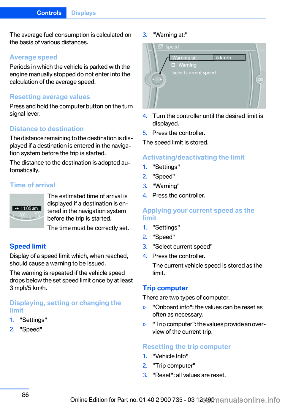
Displaying, setting or changing the
limit1."Settings"2."Speed"3."Warning at:"4.Turn the controller until the desired limit is
displayed.5.Press the controller.
The speed limit is stored.
Activating/deactivating the limit
1."Settings"2."Speed"3."Warning"4.Press the controller.
Applying your current speed as the
limit
1."Settings"2."Speed"3."Select current speed"4.Press the controller.
The current vehicle speed is stored as the
limit.
Trip computer
There are two types of computer.
▷"Onboard info": the values can be reset as
often as necessary.▷" Trip computer": the values provide an over‐
view of the current trip.
Resetting the trip computer
1."Vehicle Info"2."Trip computer"3."Reset": all values are reset.Seite 86ControlsDisplays86
Online Edition for Part no. 01 40 2 900 735 - 03 12 490
Page 87 of 297
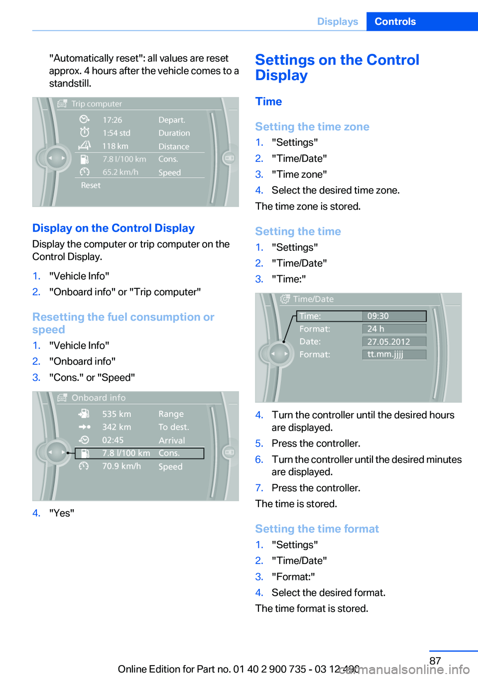
"Automatically reset": all values are reset
approx. 4 hours after the vehicle comes to a
standstill.
Display on the Control Display
Display the computer or trip computer on the
Control Display.
1."Vehicle Info"2."Onboard info" or "Trip computer"
Resetting the fuel consumption or
speed
1."Vehicle Info"2."Onboard info"3."Cons." or "Speed"4."Yes"Settings on the Control
Display
Time
Setting the time zone1."Settings"2."Time/Date"3."Time zone"4.Select the desired time zone.
The time zone is stored.
Setting the time
1."Settings"2."Time/Date"3."Time:"4.Turn the controller until the desired hours
are displayed.5.Press the controller.6.Turn the controller until the desired minutes
are displayed.7.Press the controller.
The time is stored.
Setting the time format
1."Settings"2."Time/Date"3."Format:"4.Select the desired format.
The time format is stored.
Seite 87DisplaysControls87
Online Edition for Part no. 01 40 2 900 735 - 03 12 490
Page 88 of 297
Date
Setting the date1."Settings"2."Time/Date"3."Date:"4.Turn the controller until the desired day is
displayed.5.Press the controller.6.Make the necessary settings for the month
and year.
The date is stored.
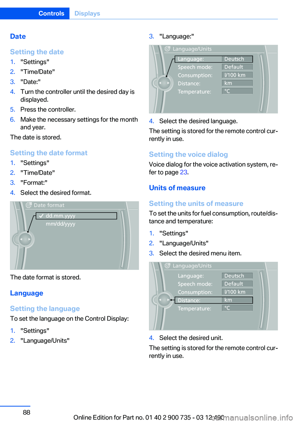
Setting the date format
1."Settings"2."Time/Date"3."Format:"4.Select the desired format.
The date format is stored.
Language
Setting the language
To set the language on the Control Display:
1."Settings"2."Language/Units"3."Language:"4.Select the desired language.
The setting is stored for the remote control cur‐
rently in use.
Setting the voice dialog
Voice dialog for the voice activation system, re‐
fer to page 23.
Units of measure
Setting the units of measure
To set the units for fuel consumption, route/dis‐
tance and temperature:
1."Settings"2."Language/Units"3.Select the desired menu item.4.Select the desired unit.
The setting is stored for the remote control cur‐
rently in use.
Seite 88ControlsDisplays88
Online Edition for Part no. 01 40 2 900 735 - 03 12 490
Page 89 of 297
Brightness
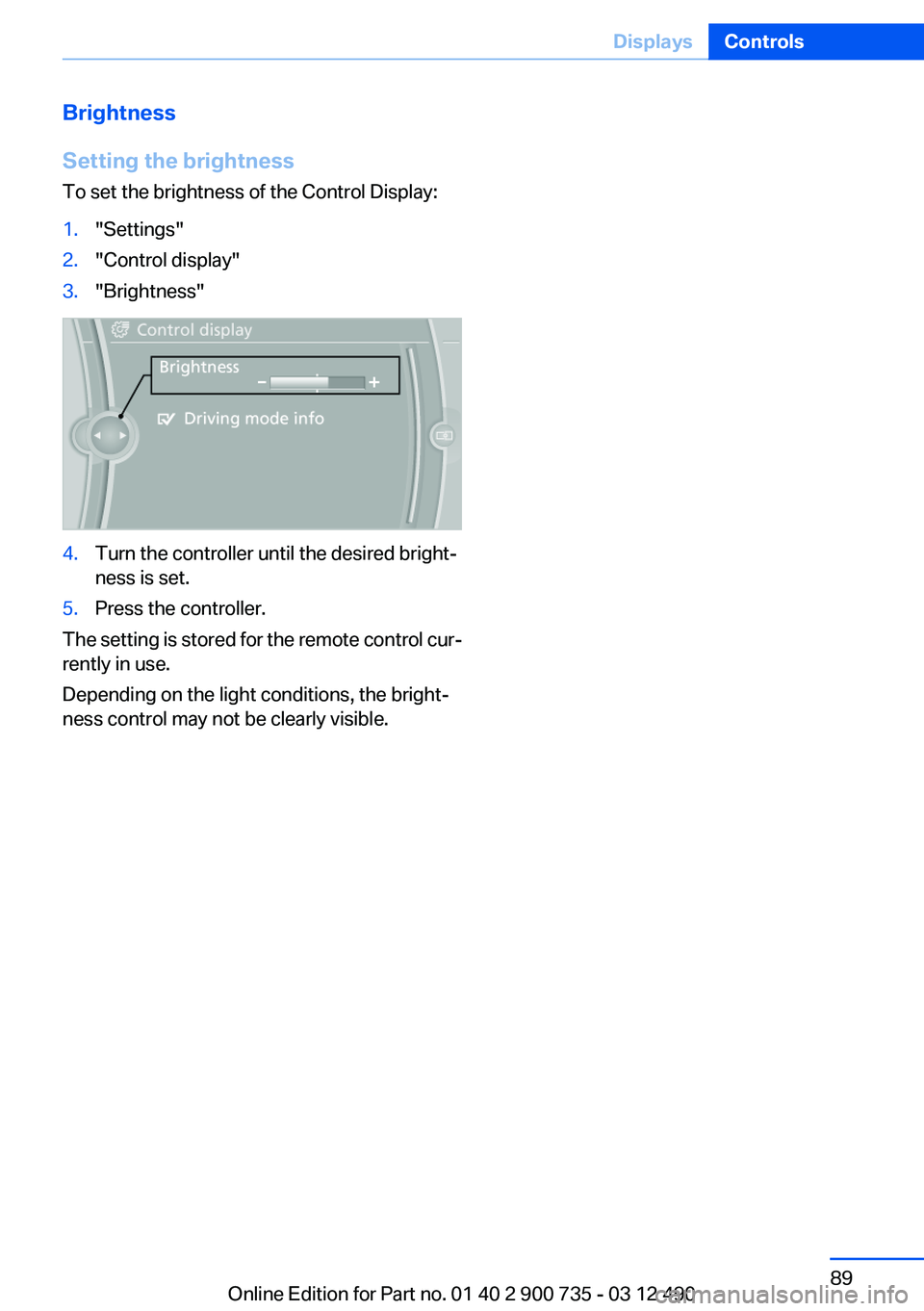
Setting the brightness
To set the brightness of the Control Display:1."Settings"2."Control display"3."Brightness"4.Turn the controller until the desired bright‐
ness is set.5.Press the controller.
The setting is stored for the remote control cur‐
rently in use.
Depending on the light conditions, the bright‐
ness control may not be clearly visible.
Seite 89DisplaysControls89
Online Edition for Part no. 01 40 2 900 735 - 03 12 490
Page 90 of 297
LampsVehicle equipment
All standard, country-specific and optional
equipment that is offered in the model series is
described in this chapter. Therefore, equipment
is also described that is not available in a vehicle,
e. g., because of the selected optional equip‐
ment or country variant. This also applies for
safety-related functions and systems.
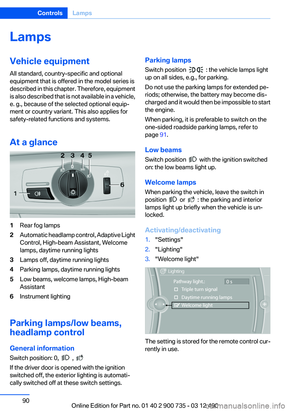
At a glance1Rear fog lamps2Automatic headlamp control, Adaptive Light
Control, High-beam Assistant, Welcome
lamps, daytime running lights3Lamps off, daytime running lights4Parking lamps, daytime running lights5Low beams, welcome lamps, High-beam
Assistant6Instrument lighting
Parking lamps/low beams,
headlamp control
General information
Switch position: 0,
,
If the driver door is opened with the ignition
switched off, the exterior lighting is automati‐
cally switched off at these switch settings.
Parking lamps
Switch position
: the vehicle lamps light
up on all sides, e.g., for parking.
Do not use the parking lamps for extended pe‐
riods; otherwise, the battery may become dis‐
charged and it would then be impossible to start
the engine.
When parking, it is preferable to switch on the
one-sided roadside parking lamps, refer to
page 91.
Low beams
Switch position
with the ignition switched
on: the low beams light up.
Welcome lamps
When parking the vehicle, leave the switch in
position
or : the parking and interior
lamps light up briefly when the vehicle is un‐
locked.
Activating/deactivating
1."Settings"2."Lighting"3."Welcome light"
The setting is stored for the remote control cur‐
rently in use.
Seite 90ControlsLamps90
Online Edition for Part no. 01 40 2 900 735 - 03 12 490