service BMW M6 CONVERTIBLE 2013 F12 User Guide
[x] Cancel search | Manufacturer: BMW, Model Year: 2013, Model line: M6 CONVERTIBLE, Model: BMW M6 CONVERTIBLE 2013 F12Pages: 222, PDF Size: 7.3 MB
Page 53 of 222
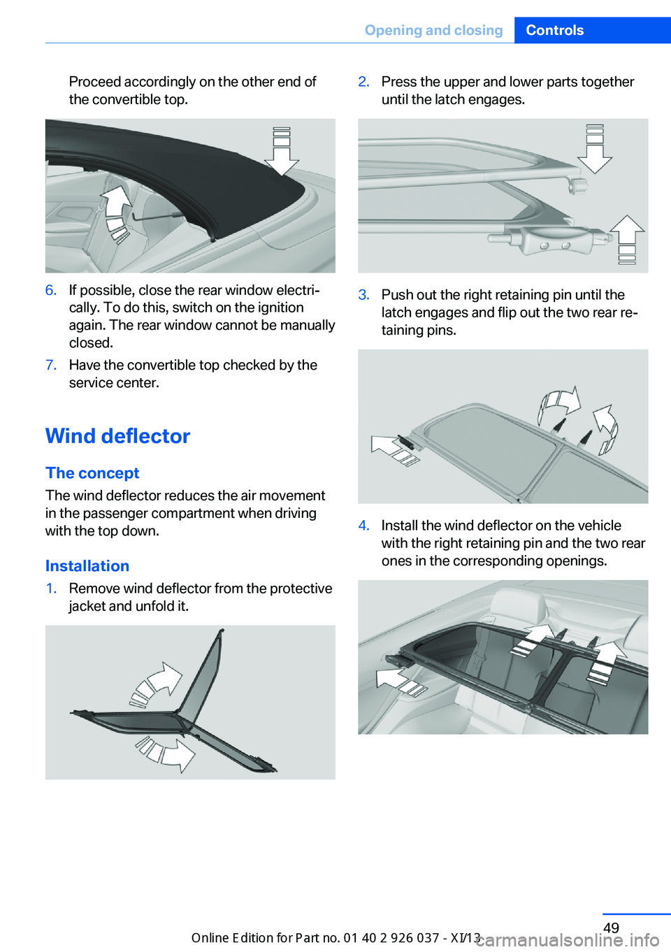
Proceed accordingly on the other end of
the convertible top.6.If possible, close the rear window electri‐
cally. To do this, switch on the ignition
again. The rear window cannot be manually
closed.7.Have the convertible top checked by the
service center.
Wind deflector
The concept The wind deflector reduces the air movement
in the passenger compartment when driving
with the top down.
Installation
1.Remove wind deflector from the protective
jacket and unfold it.2.Press the upper and lower parts together
until the latch engages.3.Push out the right retaining pin until the
latch engages and flip out the two rear re‐
taining pins.4.Install the wind deflector on the vehicle
with the right retaining pin and the two rear
ones in the corresponding openings.Seite 49Opening and closingControls49
Online Edition for Part no. 01 40 2 910 746 - VI/13
Page 59 of 222
Checking and replacing safety belts
Have the work performed only by your
service center; otherwise, it cannot be ensured
that this safety feature will function properly.◀
Front Head restraints
Correctly adjusted head restraint
A correctly adjusted head restraint reduces the
risk of injury to cervical vertebrae in the event
of an accident.
Adjusting the head restraint
Correctly adjust the head restraints of all
occupied seats; otherwise, there is an in‐
creased risk of injury in an accident.◀
Height Adjust the head restraint so that its center is
approximately at ear level.
Distance
Adjust the distance so that the head restraint
is as close as possible to the back of the head.
Active head restraint In the event of a rear-end collision with a cer‐
tain severity, the active head restraint automat‐
ically reduces the distance from the head.
Reduced protective function▷Do not use seat or head restraint
covers.▷Do not hang objects, e.g., clothes hangers,
on the head restraints.▷Only attach accessories approved by BMW
to the seat or head restraint.
Otherwise, the protective function of the active
head restraint will be impaired and the per‐
sonal safety of the occupants will be endan‐
gered.◀
In the case of strain caused by accidents or
damage:
Have the active headrest checked and if nec‐
essary replaced.
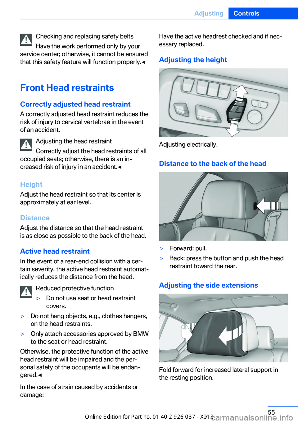
Adjusting the height
Adjusting electrically.
Distance to the back of the head
▷Forward: pull.▷Back: press the button and push the head
restraint toward the rear.
Adjusting the side extensions
Fold forward for increased lateral support in
the resting position.
Seite 55AdjustingControls55
Online Edition for Part no. 01 40 2 910 746 - VI/13
Page 84 of 222
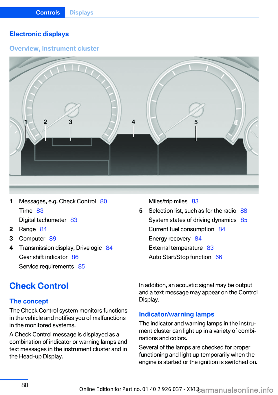
Electronic displays
Overview, instrument cluster1Messages, e.g. Check Control 80
Time 83
Digital tachometer 832Range 843Computer 894Transmission display, Drivelogic 84
Gear shift indicator 86
Service requirements 85Miles/trip miles 835Selection list, such as for the radio 88
System states of driving dynamics 85
Current fuel consumption 84
Energy recovery 84
External temperature 83
Auto Start/Stop function 66Check Control
The concept The Check Control system monitors functions
in the vehicle and notifies you of malfunctions
in the monitored systems.
A Check Control message is displayed as a
combination of indicator or warning lamps and
text messages in the instrument cluster and in
the Head-up Display.In addition, an acoustic signal may be output
and a text message may appear on the Control Display.
Indicator/warning lamps The indicator and warning lamps in the instru‐
ment cluster can light up in a variety of combi‐
nations and colors.
Several of the lamps are checked for proper
functioning and light up temporarily when the
engine is started or the ignition is switched on.Seite 80ControlsDisplays80
Online Edition for Part no. 01 40 2 910 746 - VI/13
Page 86 of 222
The supplementary text of urgent messages is
automatically displayed on the Control Display.
Symbols
Depending on the Check Control message, the
following functions can be selected.▷ "Owner's Manual"
Display additional information about the
Check Control message in the Integrated
Owner's Manual.▷ "Service request"
Contact the service partner.▷ "Roadside Assistance"
Contact Roadside Assistance.
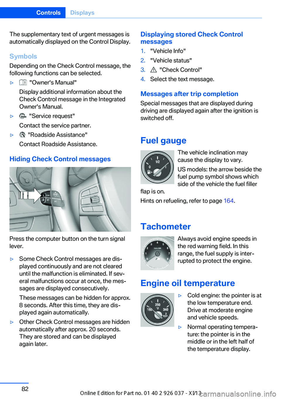
Hiding Check Control messages
Press the computer button on the turn signal
lever.
▷Some Check Control messages are dis‐
played continuously and are not cleared
until the malfunction is eliminated. If sev‐
eral malfunctions occur at once, the mes‐
sages are displayed consecutively.
These messages can be hidden for approx.
8 seconds. After this time, they are dis‐
played again automatically.▷Other Check Control messages are hidden
automatically after approx. 20 seconds.
They are stored and can be displayed
again later.Displaying stored Check Control
messages1."Vehicle Info"2."Vehicle status"3. "Check Control"4.Select the text message.
Messages after trip completion
Special messages that are displayed during
driving are displayed again after the ignition is
switched off.
Fuel gauge The vehicle inclination may
cause the display to vary.
US models: the arrow beside the
fuel pump symbol shows which
side of the vehicle the fuel filler
flap is on.
Hints on refueling, refer to page 164.
Tachometer Always avoid engine speeds inthe red warning field. In this
range, the fuel supply is inter‐
rupted to protect the engine.
Engine oil temperature
▷Cold engine: the pointer is at
the low temperature end.
Drive at moderate engine
and vehicle speeds.▷Normal operating tempera‐
ture: the pointer is in the
middle or in the left half of
the temperature display.Seite 82ControlsDisplays82
Online Edition for Part no. 01 40 2 910 746 - VI/13
Page 89 of 222
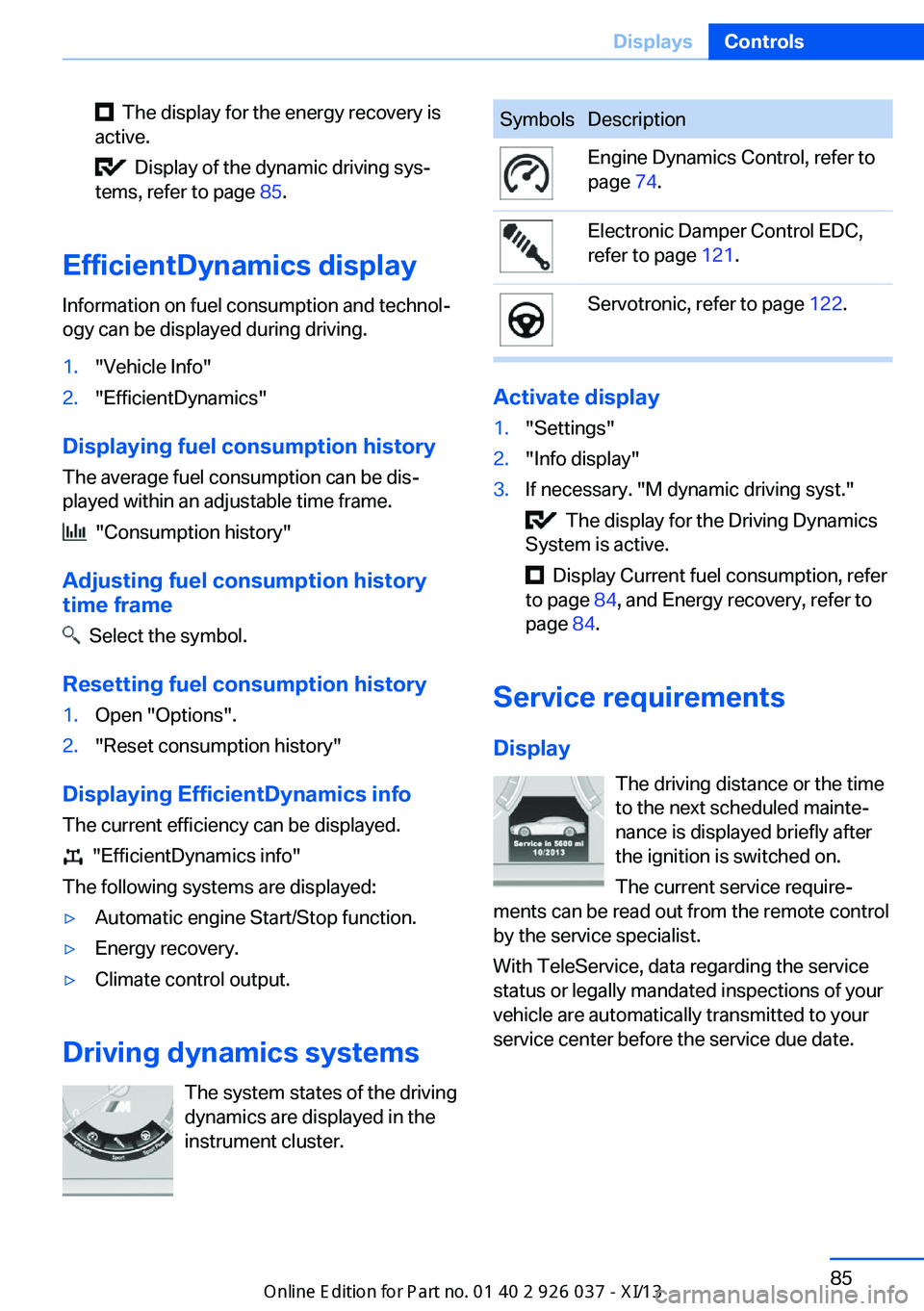
The display for the energy recovery is
active.
Display of the dynamic driving sys‐
tems, refer to page 85.
EfficientDynamics display
Information on fuel consumption and technol‐
ogy can be displayed during driving.
1."Vehicle Info"2."EfficientDynamics"
Displaying fuel consumption history
The average fuel consumption can be dis‐
played within an adjustable time frame.
"Consumption history"
Adjusting fuel consumption history time frame
Select the symbol.
Resetting fuel consumption history
1.Open "Options".2."Reset consumption history"
Displaying EfficientDynamics info
The current efficiency can be displayed.
"EfficientDynamics info"
The following systems are displayed:
▷Automatic engine Start/Stop function.▷Energy recovery.▷Climate control output.
Driving dynamics systems
The system states of the driving
dynamics are displayed in the
instrument cluster.
SymbolsDescriptionEngine Dynamics Control, refer to
page 74.Electronic Damper Control EDC,
refer to page 121.Servotronic, refer to page 122.
Activate display
1."Settings"2."Info display"3.If necessary. "M dynamic driving syst."
The display for the Driving Dynamics
System is active.
Display Current fuel consumption, refer
to page 84, and Energy recovery, refer to
page 84.
Service requirements
Display The driving distance or the time
to the next scheduled mainte‐
nance is displayed briefly after
the ignition is switched on.
The current service require‐
ments can be read out from the remote control
by the service specialist.
With TeleService, data regarding the service
status or legally mandated inspections of your
vehicle are automatically transmitted to your
service center before the service due date.
Seite 85DisplaysControls85
Online Edition for Part no. 01 40 2 910 746 - VI/13
Page 90 of 222
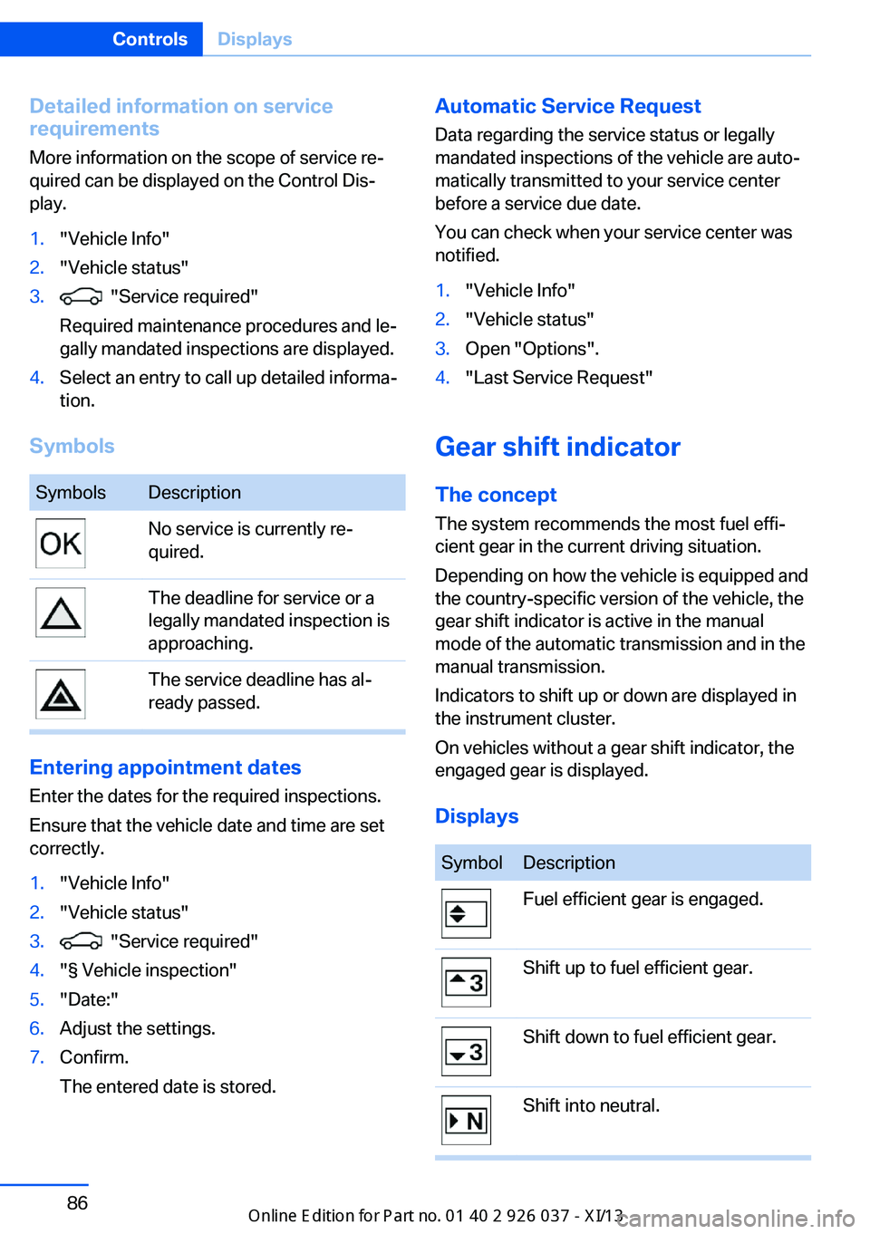
Detailed information on service
requirements
More information on the scope of service re‐
quired can be displayed on the Control Dis‐
play.1."Vehicle Info"2."Vehicle status"3. "Service required"
Required maintenance procedures and le‐
gally mandated inspections are displayed.4.Select an entry to call up detailed informa‐
tion.
Symbols
SymbolsDescriptionNo service is currently re‐
quired.The deadline for service or a
legally mandated inspection is
approaching.The service deadline has al‐
ready passed.
Entering appointment dates
Enter the dates for the required inspections.
Ensure that the vehicle date and time are set
correctly.
1."Vehicle Info"2."Vehicle status"3. "Service required"4."§ Vehicle inspection"5."Date:"6.Adjust the settings.7.Confirm.
The entered date is stored.Automatic Service Request
Data regarding the service status or legally
mandated inspections of the vehicle are auto‐
matically transmitted to your service center
before a service due date.
You can check when your service center was
notified.1."Vehicle Info"2."Vehicle status"3.Open "Options".4."Last Service Request"
Gear shift indicator
The conceptThe system recommends the most fuel effi‐
cient gear in the current driving situation.
Depending on how the vehicle is equipped and
the country-specific version of the vehicle, the
gear shift indicator is active in the manual
mode of the automatic transmission and in the
manual transmission.
Indicators to shift up or down are displayed in
the instrument cluster.
On vehicles without a gear shift indicator, the
engaged gear is displayed.
Displays
SymbolDescriptionFuel efficient gear is engaged.Shift up to fuel efficient gear.Shift down to fuel efficient gear.Shift into neutral.Seite 86ControlsDisplays86
Online Edition for Part no. 01 40 2 910 746 - VI/13
Page 103 of 222
▷Keep at a distance from the airbags.▷Always grasp the steering wheel on the
steering wheel rim, holding your hands at
the 3 o'clock and 9 o'clock positions, to
keep the danger of injury to your hands or
arms as low as possible if the airbag is trig‐
gered.▷There should be no people, animals, or ob‐
jects between an airbag and a person.▷Do not use the cover of the front airbag on
the front passenger side as a storage area.▷Keep the dashboard and window on the
front passenger side clear, i.e., do not
cover with adhesive labels or coverings,
and do not attach holders such as for navi‐
gation instruments and mobile phones.▷Make sure that the front passenger is sit‐
ting correctly, i.e., keeps his or her feet and
legs in the footwell; otherwise, leg injuries
can occur if the front airbag is triggered.▷Do not place slip covers, seat cushions or
other objects on the front passenger seat
that are not approved specifically for seats
with integrated side airbags.▷Do not hang pieces of clothing, such as
jackets, over the backrests.▷Make sure that occupants keep their heads
away from the side airbag; otherwise, inju‐
ries can occur if the airbags are deployed.▷Do not remove the airbag restraint system.▷Do not remove the steering wheel.▷Do not apply adhesive materials to the air‐
bag cover panels, cover them or modify
them in any way.▷Never modify either the individual compo‐
nents or the wiring in the airbag system.
This also applies to steering wheel covers,
the dashboard, and the seats.◀
Even when all instructions are followed closely,
injury from contact with the airbags cannot be
ruled out in certain situations.
The ignition and inflation noise may lead to
short-term and, in most cases, temporary
hearing impairment in sensitive individuals.
In the case of a malfunction, deactivation
and after triggering of the airbags
Do not touch the individual components imme‐
diately after the system has been triggered;
otherwise, there is the danger of burns.
Only have the airbags checked, repaired or dis‐
mantled and the airbag generator scrapped by
your service center or a workshop that has the
necessary authorization for handling explo‐
sives.
Non-professional attempts to service the sys‐
tem could lead to failure in an emergency or
undesired triggering of the airbag, either of
which could result in injury.◀
Warnings and information on the airbags are
also found on the sun visors.
Functional readiness of the airbag
system
When the ignition is switch on, the
warning lamp in the instrument cluster
lights up briefly and thereby indicates
the operational readiness of the entire airbag
system and the belt tensioner.
Airbag system malfunctioning▷Warning lamp does not come on when the
ignition is turned on.▷The warning lamp lights up continuously.
When there is a malfunction, have the
airbag system checked immediately
When there is a malfunction, have the airbag
system checked immediately; otherwise, there
is a risk that the system does not function as
expected in the event of an accident despite
corresponding severity of the accident.◀
Seite 99SafetyControls99
Online Edition for Part no. 01 40 2 910 746 - VI/13
Page 105 of 222
Strength of the driver's and front
passenger airbag
The strength with which the driver's and front
passenger airbags are triggered depends on
the position of the driver's and front passenger
seats.
To maintain the accuracy of this function over
the long-term, calibrate the front seats when a
corresponding message appears on the Con‐
trol Display.
Calibrating the front seats A corresponding message appears on the
Control Display.1.Move the respective seat forward all the
way.2.Move the respective seat forward again. It
moves forward briefly.3.Readjust the seat to the desired position.
The calibration procedure is completed when
the message on the Control Display disap‐
pears.
If the message continues to be displayed, re‐
peat the calibration.
If the message does not disappear after a re‐
peat calibration, have the system checked as
soon as possible.
Unobstructed area of movement
Ensure that the area of movement of the
seats is unobstructed to avoid personal injury
or damage to objects.◀
Rollover protection system The concept
The rollover protection system is automatically
activated in the event of a sufficiently serious
accident or if the longitudinal axis is tilted ex‐
cessively. The safety frames located behind
the rear headrests extend within fractions of a
second.
Supplementing the reinforced front windshield
frame, the rollover protection system further
increases passenger safety.
Maintaining movement space
Always keep the movement space of the
rollover protection system clear. Otherwise,
there may be damage or injuries when the roll‐
over protection system is triggered.◀
Triggered rollover protection system After deployment or damage
After deployment of the rollover protec‐
tion system or in the event of damage, have
the system checked and replaced.
Have this work performed only by your service
center; otherwise, it cannot be ensured that
this safety feature will function properly.◀
Do not move convertible top
When the rollover protection system is
extended, do not move the convertible top.
Otherwise, damages or injuries may result.◀
If the rollover protection system was not
placed under any stress after an automatic
triggering, it can be pushed back by hand, e.g.
to close the convertible top. Three people are
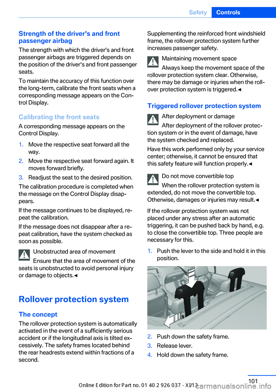
necessary for this.1.Push the lever to the side and hold it in this
position.2.Push down the safety frame.3.Release lever.4.Hold down the safety frame.Seite 101SafetyControls101
Online Edition for Part no. 01 40 2 910 746 - VI/13
Page 106 of 222
5.Proceed likewise with the second safety
frame.6.Close the convertible top
In the event of malfunctions, deactivation
or after deployment
Only have the airbags checked, repaired or dis‐
mantled and the system scrapped by your
service center. Non-professional attempts to
service the system could lead to failure in an
emergency or undesired triggering of the air‐
bag, either of which could result in injury.◀
Malfunction A Check Control message is displayed
when there is a malfunction.
Tire Pressure Monitor TPM
The concept The system monitors tire pressure in the four
mounted tires. The system warns you if there
is a significant loss of pressure in one or more
tires. For this purpose, sensors in the tire
valves measure the tire pressure and tire tem‐
perature.
Hints Tire damage due to external factors
Sudden tire damage caused by external
influences cannot be indicated in advance.◀
Pay attention to the other information and indi‐
cations under Tire inflation pressure, refer to
page 167, as well when using the system.
Functional requirements
The system must have been reset with the
correct tire inflation pressure; otherwise, relia‐
ble signaling of tire pressure loss is not en‐
sured.
Reset the system again after each correction
of the tire inflation pressure and after every tire
or wheel change.
Always use wheels with TPM electronics to
ensure that the system will operate properly.
Status display
The current status of the Tire Pressure Moni‐
tor TPM can be displayed on the Control Dis‐
play, e.g., whether or not the TPM is active.1."Vehicle Info"2."Vehicle status"3. "Tire Pressure Monitor"
The status is displayed.
Status display The tire and system status is indicated by the
color of the wheels and a text message on the
Control Display.
All wheels green System is active and will issue a warning rela‐
tive to the tire inflation pressures stored during
the last reset.
One wheel is yellow A flat tire or major drop in inflation pressure in
the indicated tire.
All wheels are yellow
A flat tire or major drop in inflation pressure in
several tires.
Wheels, grayThe system cannot detect a flat tire. Reasons
for this may be:
▷The system is being reset.▷Malfunction.
Additional information
The status display additionally shows the cur‐
rent tire inflation pressures and tire tempera‐
tures. The values shown are current measure‐
ment values and may vary depending on
driving style or weather conditions.
Seite 102ControlsSafety102
Online Edition for Part no. 01 40 2 910 746 - VI/13
Page 107 of 222
Carry out resetReset the system after each correction of the
tire inflation pressure and after every tire or
wheel change.1."Vehicle Info"2."Vehicle status"3. "Perform reset"4.Start the engine - do not drive away.5.Carry out the reset with "Perform reset".6.Drive away.
The tires are shown in gray and the status is
displayed.
After driving faster than 19 mph/30 km/h for a
short period, the tire inflation pressures set are
accepted as reference values. The reset is
completed automatically during driving.
After a successfully completed Reset, the
wheels on the Control Display are shown in
green and "Tire Pressure Monitor (TPM)
active" is displayed.
The trip can be interrupted at any time. If you
drive away again, the reset resumes automati‐
cally.
Low tire pressure message The yellow warning lamp lights up. A
Check Control message is displayed.
▷There is a flat tire or a major loss in
tire inflation pressure.▷No reset was performed for the system.
The system therefore issues a warning
based on the tire pressures before the last
reset.1.Reduce your speed and stop cautiously.
Avoid sudden braking and steering maneu‐
vers.2.Identify the damaged wheel. Do so by
checking the tire inflation pressure using
the Mobility System. Correcting the tire in‐
flation pressure, refer to page 175.3.Repair flat tire with the Mobility System, re‐
fer to page 172, or replace the damaged
wheel.
Required inflation pressure check
message
A Check Control message is displayed.
Check the tire inflation pressure and carry out
a reset of the system.
In some cases, a wheel was changed without
having carried out a reset.
System limits
The system does not function properly if a re‐
set has not been carried out, e.g., a flat tire is
reported even though the tire inflation pres‐
sures are correct.
The tire pressure depends on the temperature
of the tire. If the tire temperature rises, e.g.,
due to driving or because of the heat of the
Sun, the tire inflation pressure increases also.
The tire pressure is reduced when the tire
temperature falls again. This behavior may
cause a warning to be issued if temperatures
fall very sharply.
Malfunction The yellow warning lamp flashes and
then lights up continuously. A Check
Control message is displayed. No flat
tire or loss of tire pressure can be detected.
Display in the following situations:
▷A wheel without TPM electronics is fitted:
have the service center check it if neces‐
sary.▷Malfunction: have the system checked by
your service center.▷TPM was unable to complete the reset.
Reset the system again.▷Disturbance by systems or devices with
the same radio frequency: after leaving the
area of the disturbance, the system auto‐
matically becomes active again.Seite 103SafetyControls103
Online Edition for Part no. 01 40 2 910 746 - VI/13