reset BMW M6 CONVERTIBLE 2014 F12M Owner's Manual
[x] Cancel search | Manufacturer: BMW, Model Year: 2014, Model line: M6 CONVERTIBLE, Model: BMW M6 CONVERTIBLE 2014 F12MPages: 228, PDF Size: 5.02 MB
Page 40 of 228
Adjusting
The settings for the following systems and
functions are saved in the active profile. The
scope of storable settings is country- and
equipment-dependable.▷Unlocking and locking.▷Lights.▷Climate control.▷Radio.▷Instrument cluster.▷Programmable memory buttons.▷Volumes, tone.▷Control Display.▷Navigation.▷TV.▷Park Distance Control PDC.▷Rearview camera▷Side View.▷Head-up Display.▷M Drive: configurations.▷Driver's seat position, exterior mirror posi‐
tion, steering wheel position.▷Intelligent Safety.▷Active Blind Spot Detection.▷Night vision.
Profile management
Opening profiles Regardless of the remote control in use a dif‐
ferent profile may be activated.
1."Settings"2."Profiles"3.Select a profile.
The activated profile is assigned to the cur‐
rently used remote control.
Renaming profiles1."Settings"2."Profiles"3."Options"4."Rename current profile"
Resetting profiles
The settings of the active profile are reset to
their default values.
1."Settings"2."Profiles"3."Options"4."Reset current profile"
Exporting profiles
Most settings of the active profile and the
saved contacts can be exported.
This can be helpful for securing and retrieving
personal settings, before delivering the vehicle
to a workshop, e.g. Profiles can be taken to an‐
other vehicle equipped with the Personal Pro‐
file function.
The following export options are available:
▷Via BMW Online.▷Via the USB port to a USB device.
Popular file systems for USB devices are
supported. FAT32 and exFAT are the rec‐
ommended formats for profile export.
Other formats may not support the export.1."Settings"2."Profiles"3."Export profile"4.BMW Online: "BMW Online"
USB port: "USB device"
Importing profiles
Profiles exported via BMW Online can also be
imported via BMW Online.
Profiles stored on a USB device can be im‐
ported via the USB interface.
Seite 36ControlsOpening and closing36
Online Edition for Part no. 0140 2 956 361 - X/14
Page 69 of 228
On the Control Display:1."Settings"2."M Drive 1" or "M Drive 2"3.Select the desired setting option.4.Select the desired channel.
Individual settings are stored for the profile
currently in use.
If M Drive is activated, a change in the setting
on the Control Display is immediately adopted.
Activating/deactivating M Drive
Activating Press the corresponding button on the steer‐
ing wheel:
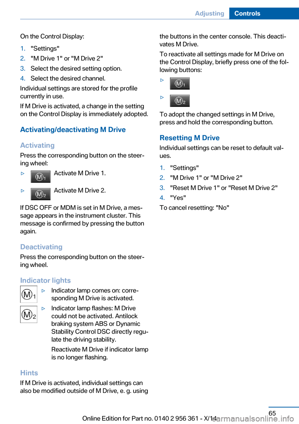
▷Activate M Drive 1.▷Activate M Drive 2.
If DSC OFF or MDM is set in M Drive, a mes‐
sage appears in the instrument cluster. This
message is confirmed by pressing the button
again.
Deactivating Press the corresponding button on the steer‐
ing wheel.
Indicator lights
▷Indicator lamp comes on: corre‐
sponding M Drive is activated.▷Indicator lamp flashes: M Drive
could not be activated. Antilock
braking system ABS or Dynamic
Stability Control DSC directly regu‐
late the driving stability.
Reactivate M Drive if indicator lamp
is no longer flashing.
Hints
If M Drive is activated, individual settings can
also be modified outside of M Drive, e. g. using
the buttons in the center console. This deacti‐
vates M Drive.
To reactivate all settings made for M Drive on
the Control Display, briefly press one of the fol‐
lowing buttons:▷▷
To adopt the changed settings in M Drive,
press and hold the corresponding button.
Resetting M Drive
Individual settings can be reset to default val‐
ues.
1."Settings"2."M Drive 1" or "M Drive 2"3."Reset M Drive 1" or "Reset M Drive 2"4."Yes"
To cancel resetting: "No"
Seite 65AdjustingControls65
Online Edition for Part no. 0140 2 956 361 - X/14
Page 88 of 228
DisplaysVehicle features and optionsThis chapter describes all standard, country-
specific and optional features offered with the
series. It also describes features that are notnecessarily available in your car, e. g., due to
the selected options or country versions. This
also applies to safety-related functions and
systems.
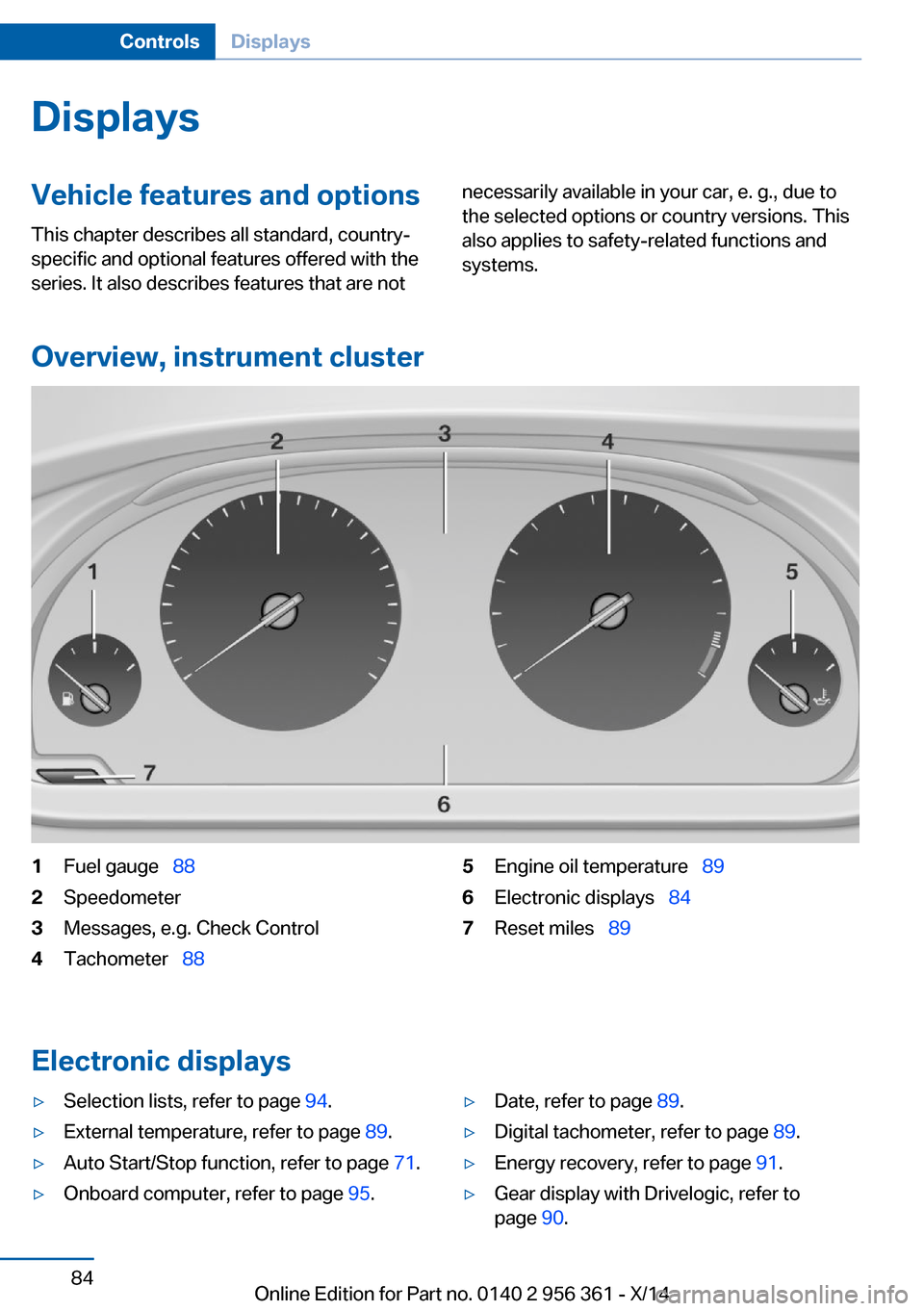
Overview, instrument cluster
1Fuel gauge 882Speedometer3Messages, e.g. Check Control4Tachometer 885Engine oil temperature 896Electronic displays 847Reset miles 89
Electronic displays
▷Selection lists, refer to page 94.▷External temperature, refer to page 89.▷Auto Start/Stop function, refer to page 71.▷Onboard computer, refer to page 95.▷Date, refer to page 89.▷Digital tachometer, refer to page 89.▷Energy recovery, refer to page 91.▷Gear display with Drivelogic, refer to
page 90.Seite 84ControlsDisplays84
Online Edition for Part no. 0140 2 956 361 - X/14
Page 90 of 228
Intervention by braking or make an evasive ma‐
neuver.
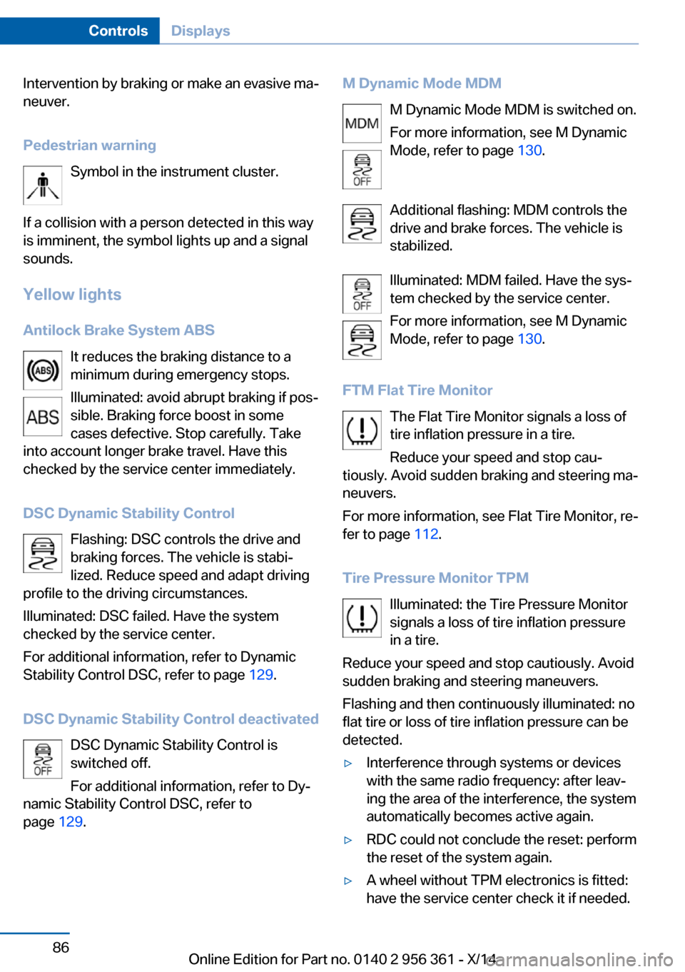
Pedestrian warning Symbol in the instrument cluster.
If a collision with a person detected in this way
is imminent, the symbol lights up and a signal
sounds.
Yellow lights
Antilock Brake System ABS It reduces the braking distance to a
minimum during emergency stops.
Illuminated: avoid abrupt braking if pos‐
sible. Braking force boost in some
cases defective. Stop carefully. Take
into account longer brake travel. Have this
checked by the service center immediately.
DSC Dynamic Stability Control Flashing: DSC controls the drive and
braking forces. The vehicle is stabi‐
lized. Reduce speed and adapt driving
profile to the driving circumstances.
Illuminated: DSC failed. Have the system
checked by the service center.
For additional information, refer to Dynamic
Stability Control DSC, refer to page 129.
DSC Dynamic Stability Control deactivated DSC Dynamic Stability Control is
switched off.
For additional information, refer to Dy‐
namic Stability Control DSC, refer to
page 129.M Dynamic Mode MDM
M Dynamic Mode MDM is switched on.
For more information, see M Dynamic
Mode, refer to page 130.
Additional flashing: MDM controls the
drive and brake forces. The vehicle is
stabilized.
Illuminated: MDM failed. Have the sys‐
tem checked by the service center.
For more information, see M Dynamic
Mode, refer to page 130.
FTM Flat Tire Monitor The Flat Tire Monitor signals a loss of
tire inflation pressure in a tire.
Reduce your speed and stop cau‐
tiously. Avoid sudden braking and steering ma‐
neuvers.
For more information, see Flat Tire Monitor, re‐
fer to page 112.
Tire Pressure Monitor TPM Illuminated: the Tire Pressure Monitor
signals a loss of tire inflation pressure
in a tire.
Reduce your speed and stop cautiously. Avoid
sudden braking and steering maneuvers.
Flashing and then continuously illuminated: no
flat tire or loss of tire inflation pressure can be
detected.▷Interference through systems or devices
with the same radio frequency: after leav‐
ing the area of the interference, the system
automatically becomes active again.▷RDC could not conclude the reset: perform
the reset of the system again.▷A wheel without TPM electronics is fitted:
have the service center check it if needed.Seite 86ControlsDisplays86
Online Edition for Part no. 0140 2 956 361 - X/14
Page 93 of 228
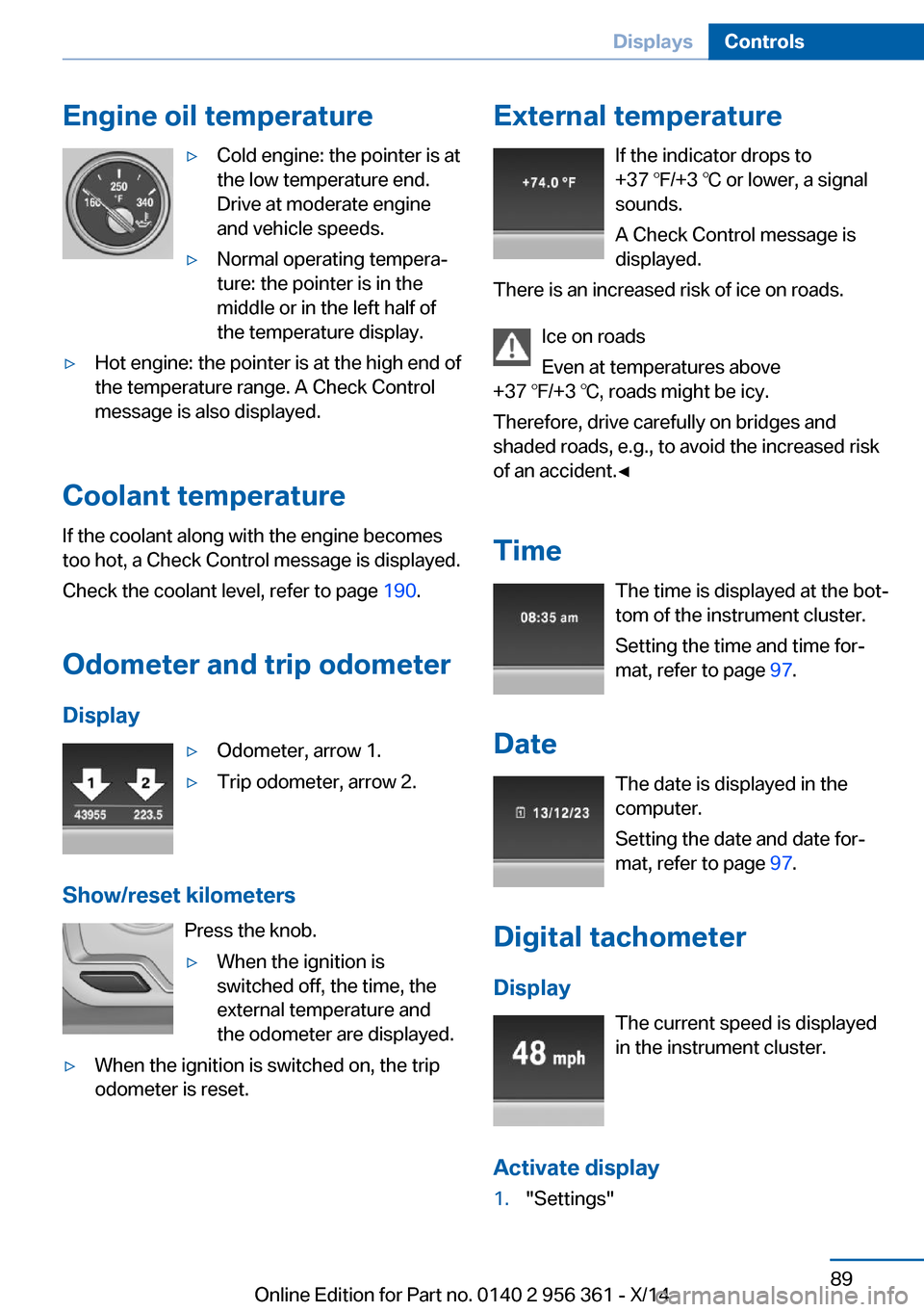
Engine oil temperature▷Cold engine: the pointer is at
the low temperature end.
Drive at moderate engine
and vehicle speeds.▷Normal operating tempera‐
ture: the pointer is in the
middle or in the left half of
the temperature display.▷Hot engine: the pointer is at the high end of
the temperature range. A Check Control
message is also displayed.
Coolant temperature
If the coolant along with the engine becomes
too hot, a Check Control message is displayed.
Check the coolant level, refer to page 190.
Odometer and trip odometer Display
▷Odometer, arrow 1.▷Trip odometer, arrow 2.
Show/reset kilometers Press the knob.
▷When the ignition is
switched off, the time, the
external temperature and
the odometer are displayed.▷When the ignition is switched on, the trip
odometer is reset.External temperature
If the indicator drops to
+37 ℉/+3 ℃ or lower, a signal
sounds.
A Check Control message is displayed.
There is an increased risk of ice on roads.
Ice on roads
Even at temperatures above
+37 ℉/+3 ℃, roads might be icy.
Therefore, drive carefully on bridges and
shaded roads, e.g., to avoid the increased risk
of an accident.◀
Time The time is displayed at the bot‐
tom of the instrument cluster.
Setting the time and time for‐
mat, refer to page 97.
Date The date is displayed in the
computer.
Setting the date and date for‐
mat, refer to page 97.
Digital tachometer
Display The current speed is displayed
in the instrument cluster.
Activate display1."Settings"Seite 89DisplaysControls89
Online Edition for Part no. 0140 2 956 361 - X/14
Page 95 of 228
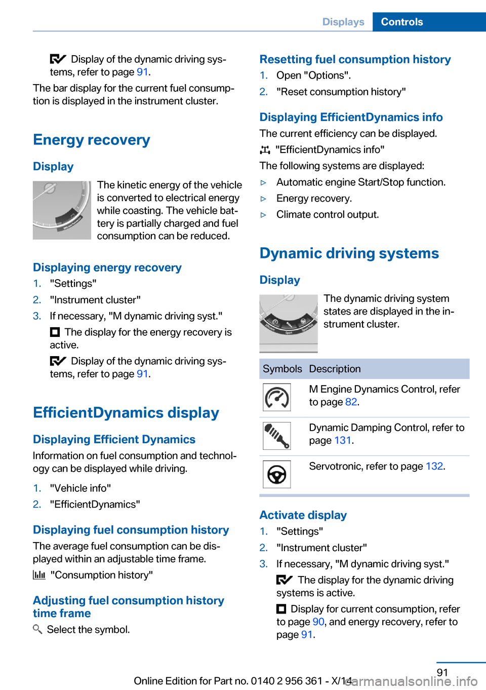
Display of the dynamic driving sys‐
tems, refer to page 91.
The bar display for the current fuel consump‐
tion is displayed in the instrument cluster.
Energy recovery
Display The kinetic energy of the vehicle
is converted to electrical energy
while coasting. The vehicle bat‐
tery is partially charged and fuel
consumption can be reduced.
Displaying energy recovery
1."Settings"2."Instrument cluster"3.If necessary, "M dynamic driving syst."
The display for the energy recovery is
active.
Display of the dynamic driving sys‐
tems, refer to page 91.
EfficientDynamics display
Displaying Efficient Dynamics
Information on fuel consumption and technol‐ ogy can be displayed while driving.
1."Vehicle info"2."EfficientDynamics"
Displaying fuel consumption history
The average fuel consumption can be dis‐
played within an adjustable time frame.
"Consumption history"
Adjusting fuel consumption history time frame
Select the symbol.
Resetting fuel consumption history1.Open "Options".2."Reset consumption history"
Displaying EfficientDynamics info
The current efficiency can be displayed.
"EfficientDynamics info"
The following systems are displayed:
▷Automatic engine Start/Stop function.▷Energy recovery.▷Climate control output.
Dynamic driving systems
Display The dynamic driving system
states are displayed in the in‐
strument cluster.
SymbolsDescriptionM Engine Dynamics Control, refer
to page 82.Dynamic Damping Control, refer to
page 131.Servotronic, refer to page 132.
Activate display
1."Settings"2."Instrument cluster"3.If necessary, "M dynamic driving syst."
The display for the dynamic driving
systems is active.
Display for current consumption, refer
to page 90, and energy recovery, refer to
page 91.
Seite 91DisplaysControls91
Online Edition for Part no. 0140 2 956 361 - X/14
Page 99 of 228
Using the thumbwheel, select the desired set‐
ting and confirm it by pushing the thumbwheel.
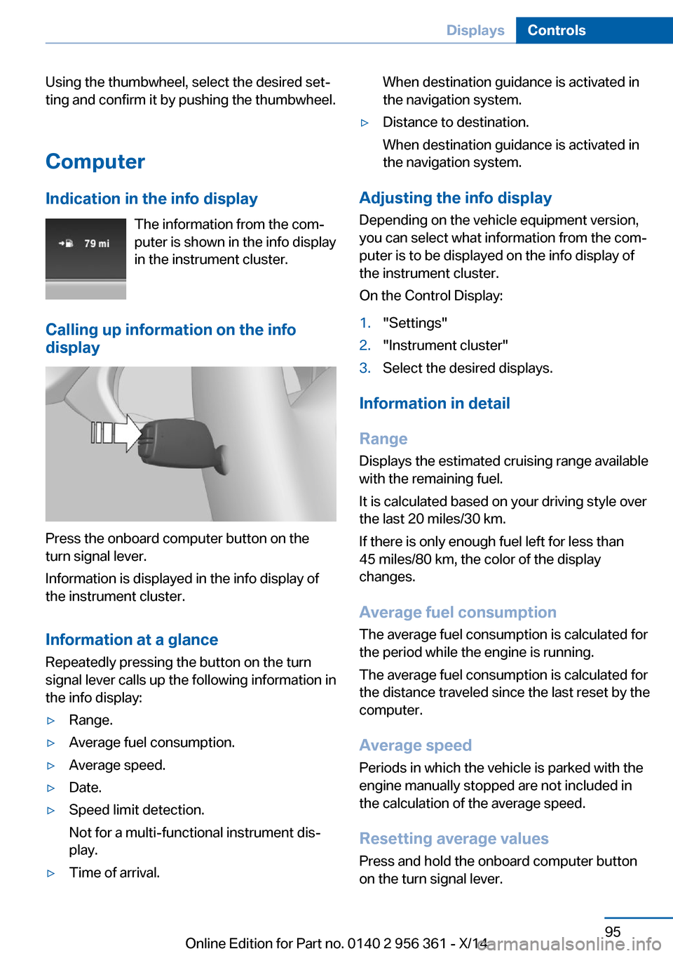
Computer
Indication in the info display The information from the com‐
puter is shown in the info display
in the instrument cluster.
Calling up information on the info display
Press the onboard computer button on the
turn signal lever.
Information is displayed in the info display of
the instrument cluster.
Information at a glance
Repeatedly pressing the button on the turn
signal lever calls up the following information in
the info display:
▷Range.▷Average fuel consumption.▷Average speed.▷Date.▷Speed limit detection.
Not for a multi-functional instrument dis‐
play.▷Time of arrival.When destination guidance is activated in
the navigation system.▷Distance to destination.
When destination guidance is activated in
the navigation system.
Adjusting the info display
Depending on the vehicle equipment version,
you can select what information from the com‐
puter is to be displayed on the info display of
the instrument cluster.
On the Control Display:
1."Settings"2."Instrument cluster"3.Select the desired displays.
Information in detail
Range
Displays the estimated cruising range available
with the remaining fuel.
It is calculated based on your driving style over
the last 20 miles/30 km.
If there is only enough fuel left for less than
45 miles/80 km, the color of the display
changes.
Average fuel consumption
The average fuel consumption is calculated for
the period while the engine is running.
The average fuel consumption is calculated for
the distance traveled since the last reset by the
computer.
Average speed
Periods in which the vehicle is parked with the
engine manually stopped are not included in
the calculation of the average speed.
Resetting average values
Press and hold the onboard computer button
on the turn signal lever.
Seite 95DisplaysControls95
Online Edition for Part no. 0140 2 956 361 - X/14
Page 100 of 228
Distance to destination
The distance remaining to the destination is
displayed if a destination is entered in the navi‐
gation system before the trip is started.
The distance to the destination is adopted au‐
tomatically.
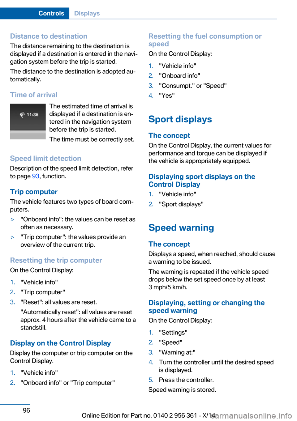
Time of arrival The estimated time of arrival is
displayed if a destination is en‐
tered in the navigation system
before the trip is started.
The time must be correctly set.
Speed limit detection
Description of the speed limit detection, refer
to page 93, function.
Trip computer
The vehicle features two types of board com‐
puters.▷"Onboard info": the values can be reset as
often as necessary.▷"Trip computer": the values provide an
overview of the current trip.
Resetting the trip computer
On the Control Display:
1."Vehicle info"2."Trip computer"3."Reset": all values are reset.
"Automatically reset": all values are reset
approx. 4 hours after the vehicle came to a
standstill.
Display on the Control Display
Display the computer or trip computer on the
Control Display.
1."Vehicle info"2."Onboard info" or "Trip computer"Resetting the fuel consumption or
speed
On the Control Display:1."Vehicle info"2."Onboard info"3."Consumpt." or "Speed"4."Yes"
Sport displays
The concept
On the Control Display, the current values for
performance and torque can be displayed if
the vehicle is appropriately equipped.
Displaying sport displays on the
Control Display
1."Vehicle info"2."Sport displays"
Speed warning
The concept Displays a speed, when reached, should cause
a warning to be issued.
The warning is repeated if the vehicle speed
drops below the set speed once by at least
3 mph/5 km/h.
Displaying, setting or changing the
speed warning
On the Control Display:
1."Settings"2."Speed"3."Warning at:"4.Turn the controller until the desired speed
is displayed.5.Press the controller.
Speed warning is stored.
Seite 96ControlsDisplays96
Online Edition for Part no. 0140 2 956 361 - X/14
Page 114 of 228
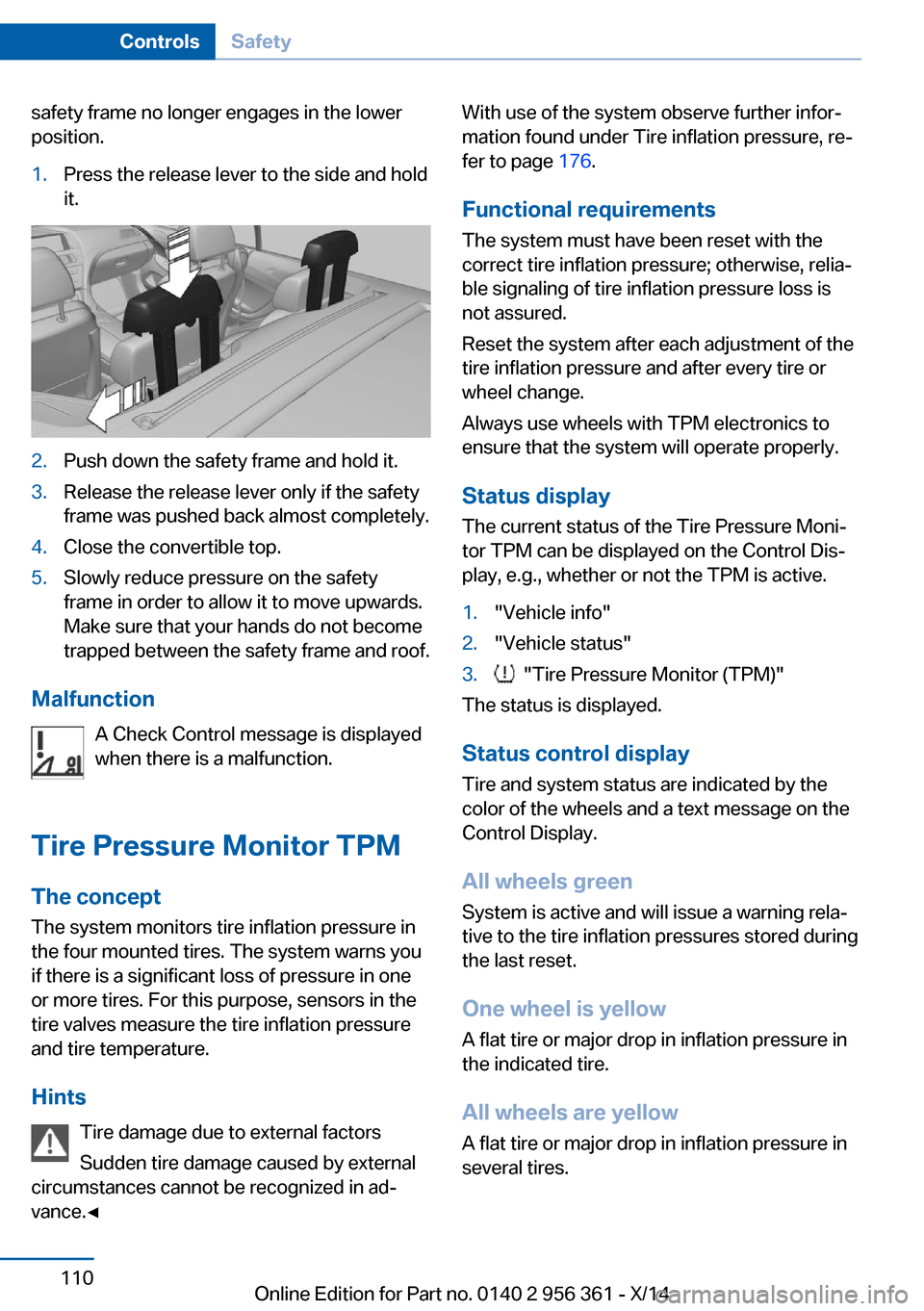
safety frame no longer engages in the lower
position.1.Press the release lever to the side and hold
it.2.Push down the safety frame and hold it.3.Release the release lever only if the safety
frame was pushed back almost completely.4.Close the convertible top.5.Slowly reduce pressure on the safety
frame in order to allow it to move upwards.
Make sure that your hands do not become
trapped between the safety frame and roof.
Malfunction
A Check Control message is displayed
when there is a malfunction.
Tire Pressure Monitor TPM The concept
The system monitors tire inflation pressure in
the four mounted tires. The system warns you
if there is a significant loss of pressure in one
or more tires. For this purpose, sensors in the
tire valves measure the tire inflation pressure
and tire temperature.
Hints Tire damage due to external factors
Sudden tire damage caused by external
circumstances cannot be recognized in ad‐
vance.◀
With use of the system observe further infor‐
mation found under Tire inflation pressure, re‐
fer to page 176.
Functional requirements The system must have been reset with the
correct tire inflation pressure; otherwise, relia‐
ble signaling of tire inflation pressure loss is
not assured.
Reset the system after each adjustment of the
tire inflation pressure and after every tire or
wheel change.
Always use wheels with TPM electronics to
ensure that the system will operate properly.
Status display The current status of the Tire Pressure Moni‐
tor TPM can be displayed on the Control Dis‐
play, e.g., whether or not the TPM is active.1."Vehicle info"2."Vehicle status"3. "Tire Pressure Monitor (TPM)"
The status is displayed.
Status control display Tire and system status are indicated by the
color of the wheels and a text message on the
Control Display.
All wheels green System is active and will issue a warning rela‐
tive to the tire inflation pressures stored during
the last reset.
One wheel is yellow A flat tire or major drop in inflation pressure in
the indicated tire.
All wheels are yellow A flat tire or major drop in inflation pressure in
several tires.
Seite 110ControlsSafety110
Online Edition for Part no. 0140 2 956 361 - X/14
Page 115 of 228
Wheels, grayThe system cannot detect a flat tire. Reasons
for this may be:▷The system is being reset.▷Malfunction.
Status information
The status control display additionally shows
the current tire inflation pressures and possibly
tire temperatures. It shows the actual values
read; they may vary depending on driving style or weather conditions.
Carry out reset
Reset the system after each adjustment of the
tire inflation pressure and after every tire or
wheel change.
On the Control Display and on the vehicle:
1."Vehicle info"2."Vehicle status"3. "Perform reset"4.Start the engine - do not drive off.5.Reset tire inflation pressure:"Perform
reset".6.Drive away.
The tires are shown in gray and the status is
displayed.
After driving faster than 19 mph/30 km/h for a
short period, the set tire inflation pressures are
accepted as reference values. The reset is
completed automatically while driving.
After a successfully completed Reset, the
wheels on the Control Display are shown in
green and "Tire Pressure Monitor (TPM)
active" is displayed.
You may interrupt this trip at any time. When
you continue the reset resumes automatically.
Low tire pressure message The yellow warning lamp lights up. A
Check Control message is displayed.
▷There is a flat tire or a major loss in tire in‐
flation pressure.▷No reset was performed for the system.
The system therefore issues a warning
based on the tire inflation pressures before
the last reset.1.Reduce your speed and stop cautiously.
Avoid sudden braking and steering maneu‐
vers.2.Identify the damaged wheel. Do so by
checking the tire inflation pressure using
the Mobility System. To correct the tire in‐
flation pressure3.Repair flat tire with the Mobility System or
replace the damaged wheel.
Required tire inflation pressure check
message
A Check Control message is displayed in the
following situations
▷The system has detected a wheel change,
but no reset was done.▷Inflation was not carried out according to
specifications.▷The tire inflation pressure has fallen below
the level of the last confirmation.
In this case:
▷Check the tire pressure and correct as
needed.▷Carry out a reset of the system after a tire
change.
System limits
The system does not function properly if a re‐
set has not been carried out, e.g., a flat tire is
reported though tire inflation pressures are
correct.
The tire inflation pressure depends on the
tire's temperature. Driving or exposure to the
sun will increase the tire's temperature, thus
increasing the tire inflation pressure. The tire
inflation pressure is reduced when the tire
Seite 111SafetyControls111
Online Edition for Part no. 0140 2 956 361 - X/14