clock BMW MOTORRAD G 650 XCOUNTRY 2007 Rider's Manual (in English)
[x] Cancel search | Manufacturer: BMW MOTORRAD, Model Year: 2007, Model line: G 650 XCOUNTRY, Model: BMW MOTORRAD G 650 XCOUNTRY 2007Pages: 126, PDF Size: 2.64 MB
Page 19 of 126
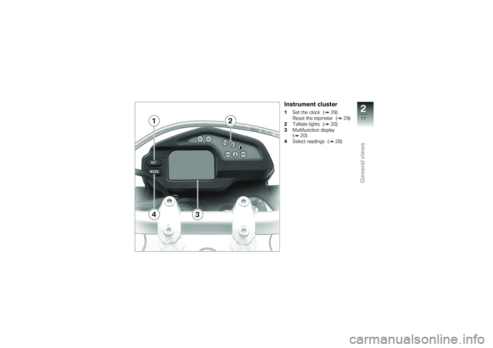
Instrument cluster1Set the clock ( 29)
Reset the tripmeter ( 29)
2 Telltale lights ( 20)
3 Multifunction display
( 20)
4 Select readings ( 28)
217zGeneral views
Page 22 of 126
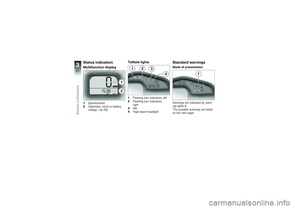
Status indicatorsMultifunction display1Speedometer
2 Odometer, clock or battery
voltage ( 28)
Telltale lights1Flashing turn indicators, left
2 Flashing turn indicators,
right
3 Idle
4 High-beam headlight
Standard warningsMode of presentation
Warnings are indicated by warn-
ing lights 1.
The possible warnings are listed
on the next page.
320zStatus indicators
Page 31 of 126
If the motorcycle is to re-
main abroad for a lengthy
period, you can have the display
readouts changed from miles to
kilometers or vice versa, if neces-
sary. Under these circumstances
consult a specialist workshop,
preferably an authorised BMW
Motorrad dealer.
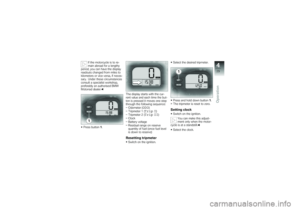
Press button 1. The display starts with the cur-
rent value and each time the but-
ton is pressed it moves one step
through the following sequence:
Odometer (
ODO
)
Tripmeter 1 (
Trip I
)
Tripmeter 2 (
Trip II
)
Clock
Battery voltage
Residual range on reserve
quantity of fuel (once fuel level
is down to reserve)
Resetting tripmeterSwitch on the ignition. Select the desired tripmeter.
Press and hold down button
1.
The tripmeter is reset to zero.
Setting clockSwitch on the ignition.
You can make this adjust-
ment only when the motor-
cycle is at a standstill.
Select the clock.
429zOperation
Page 32 of 126
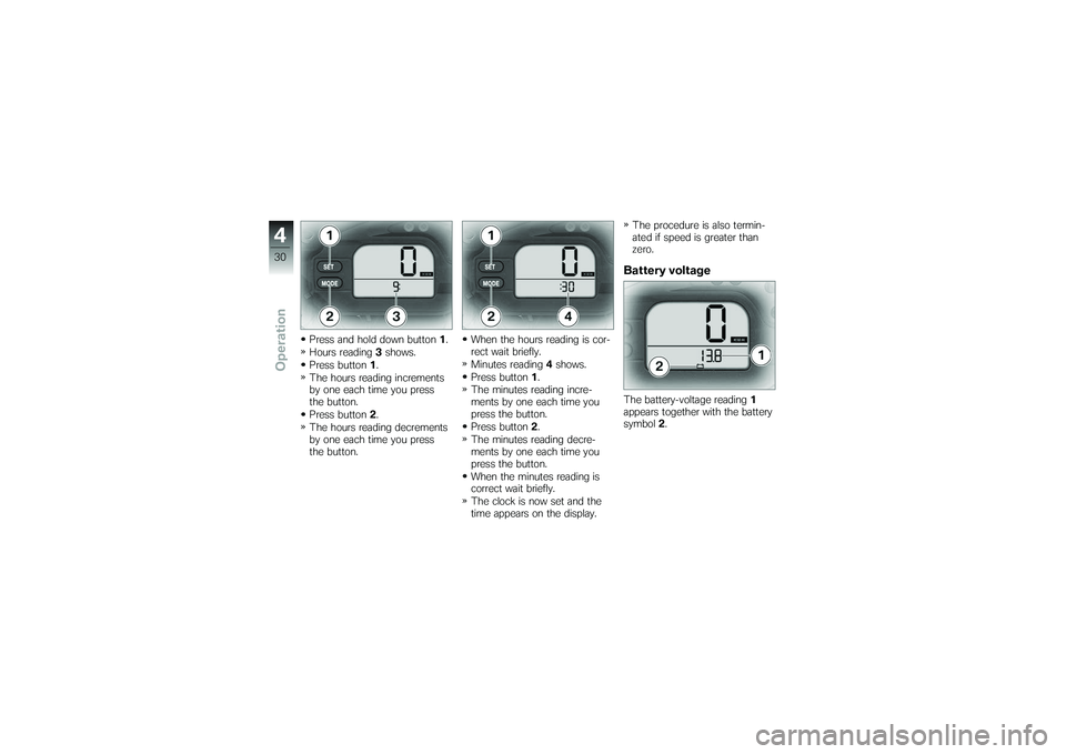
Press and hold down button1.
Hours reading 3shows.
Press button 1.
The hours reading increments
by one each time you press
the button.
Press button 2.
The hours reading decrements
by one each time you press
the button. When the hours reading is cor-
rect wait briefly.
Minutes reading
4shows.
Press button 1.
The minutes reading incre-
ments by one each time you
press the button.
Press button 2.
The minutes reading decre-
ments by one each time you
press the button.
When the minutes reading is
correct wait briefly.
The clock is now set and the
time appears on the display. The procedure is also termin-
ated if speed is greater than
zero.
Battery voltageThe battery-voltage reading
1
appears together with the battery
symbol 2.
430zOperation
Page 39 of 126
Headlight beam throw and
spring preloadHeadlight beam throw is gener-
ally kept constant when spring
preload is adjusted to suit load.
Spring preload adjustment might
not suffice only if the motorcycle
is very heavily loaded. Under
these circumstances, headlight
beam throw has to be adjusted
to suit the weight carried by the
motorcycle.Consult a specialist work-
shop, preferably an au-
thorised BMW Motorrad deal-
er, if you are unsure whether
the headlight basic setting is
correct. Screws
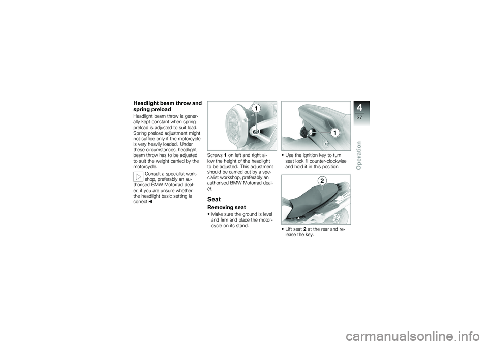
1on left and right al-
low the height of the headlight
to be adjusted. This adjustment
should be carried out by a spe-
cialist workshop, preferably an
authorised BMW Motorrad deal-
er.
SeatRemoving seatMake sure the ground is level
and firm and place the motor-
cycle on its stand. Use the ignition key to turn
seat lock
1counter-clockwise
and hold it in this position.
Lift seat 2at the rear and re-
lease the key.
437zOperation
Page 50 of 126
Refuelling
Fuel is highly flammable. A
naked flame close to the
fuel tank can cause a fire or ex-
plosion.
Do not smoke. Never bring a
naked flame near the fuel tank.
Fuel expands when hot.
Fuel escaping from an
overfilled tank could make its way
onto the rear tyre. This could
cause a fall.
Do not fill the tank past the bot-
tom edge of the filler neck.
Fuel attacks plastics, which
become dull or unsightly.
Wipe off plastic parts immediately
if they come into contact with
fuel.
Leaded fuel will destroy the
catalytic converter.
Use only unleaded fuel. Make sure the ground is level
and firm and place the motor-
cycle on its stand.
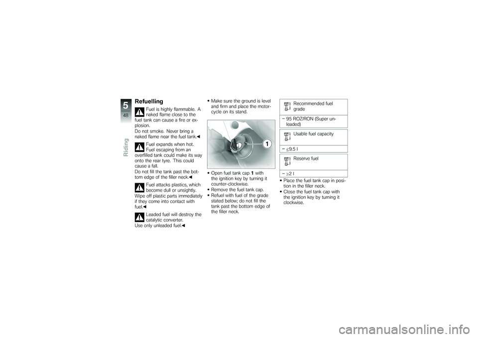
Open fuel tank cap
1with
the ignition key by turning it
counter-clockwise.
Remove the fuel tank cap.
Refuel with fuel of the grade
stated below; do not fill the
tank past the bottom edge of
the filler neck. Recommended fuel
grade
95 ROZ/RON (Super un-
leaded) Usable fuel capacity
9.5 l Reserve fuel
2l
Place the fuel tank cap in posi-
tion in the filler neck.
Close the fuel tank cap with
the ignition key by turning it
clockwise.
548zRiding
Page 62 of 126
Checking the oil level with the
engine cold or after no more than
a short ride will lead to misinter-
pretation; this in turn, means that
the engine will be operated with
the incorrect quantity of oil.
In order to ensure that the en-
gine oil level is read correctly,
check the oil level only after a
lengthy trip.Allow the engine to idle until
the fan starts up, then allow it
to idle one minute longer.
Make sure the ground is level
and firm and hold the motor-
cycle upright.
Switch off the engine.
Wipe the area around the oil
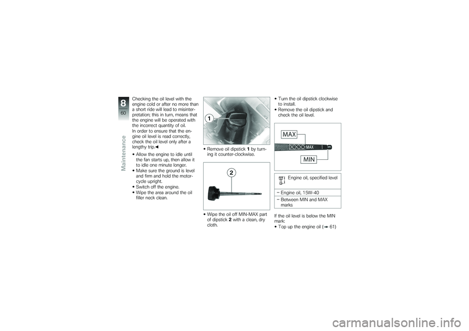
filler neck clean. Remove oil dipstick
1by turn-
ing it counter-clockwise.
Wipe the oil off MIN-MAX part
of dipstick 2with a clean, dry
cloth. Turn the oil dipstick clockwise
to install.
Remove the oil dipstick and
check the oil level.
Engine oil, specified level
Engine oil, 15W-40
Between MIN and MAX
marks
If the oil level is below the MIN
mark: Top up the engine oil ( 61)
860zMaintenance
Page 69 of 126
Install screw1.
Install the seat ( 38)
ClutchChecking clutch-lever
playPull the clutch lever until resist-
ance is perceptible.
Measure clutch-lever play A.
Clutch-lever play
2...3 mm (Engine cold)
Clutch-lever play is out of toler-
ance: Adjust clutch-lever play ( 67)
Adjusting clutch-lever
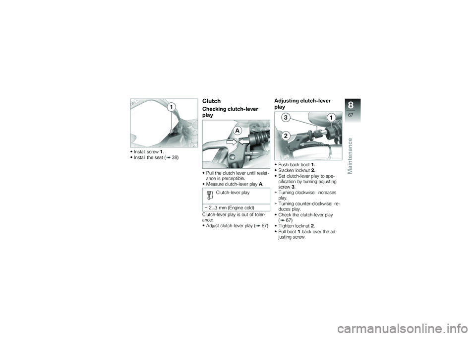
playPush back boot 1.
Slacken locknut 2.
Set clutch-lever play to spe-
cification by turning adjusting
screw 3.
Turning clockwise: increases
play.
Turning counter-clockwise: re-
duces play.
Check the clutch-lever play
( 67)
Tighten locknut 2.
Pull boot 1back over the ad-
justing screw.
867zMaintenance
Page 71 of 126
Chain deflection
25...30 mm (Motorcycle sup-
ported on its side stand)
30...35 mm (Rear suspen-
sion extended)
If measured value is outside per-
mitted tolerance: Adjust the chain tension
( 69)
Adjusting chain tensionMake sure the ground is level
and firm and place the motor-
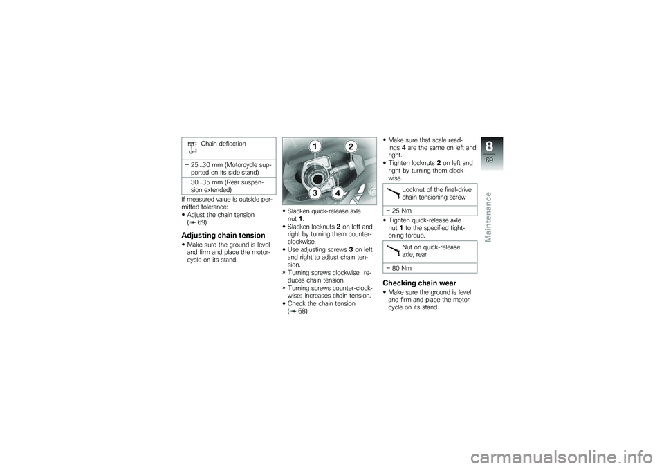
cycle on its stand. Slacken quick-release axle
nut
1.
Slacken locknuts 2on left and
right by turning them counter-
clockwise.
Use adjusting screws 3on left
and right to adjust chain ten-
sion.
Turning screws clockwise: re-
duces chain tension.
Turning screws counter-clock-
wise: increases chain tension.
Check the chain tension
( 68) Make sure that scale read-
ings
4are the same on left and
right.
Tighten locknuts 2on left and
right by turning them clock-
wise.
Locknut of the final-drive
chain tensioning screw
25 Nm
Tighten quick-release axle
nut 1to the specified tight-
ening torque.
Nut on quick-release
axle, rear
80 Nm
Checking chain wearMake sure the ground is level
and firm and place the motor-
cycle on its stand.
869zMaintenance
Page 76 of 126
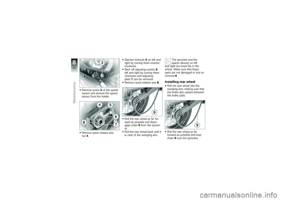
Remove screw3of the speed
sensor and remove the speed
sensor from the holder.
Remove quick-release axle
nut 4. Slacken locknuts
5on left and
right by turning them counter-
clockwise.
Back off adjusting screws 6
left and right by turning them
clockwise until adjusting
plate 7can be removed.
Remove quick-release axle 8.
Roll the rear wheel as far for-
ward as possible and disen-
gage chain 9from the sprock-
et.
Roll the rear wheel back until it
is clear of the swinging arm. The sprocket and the
spacer sleeves on left
and right are loose fits in the
wheel. Make sure that these
parts are not damaged or lost on
removal.
Installing rear wheelRoll the rear wheel into the
swinging arm, making sure that
the brake disc passes between
the brake pads.
Roll the rear wheel as far
forward as possible and loop
chain 9over the sprocket.
874zMaintenance