ECU BMW MOTORRAD K 1200 GT 2006 Rider's Manual (in English)
[x] Cancel search | Manufacturer: BMW MOTORRAD, Model Year: 2006, Model line: K 1200 GT, Model: BMW MOTORRAD K 1200 GT 2006Pages: 172, PDF Size: 1.98 MB
Page 46 of 172
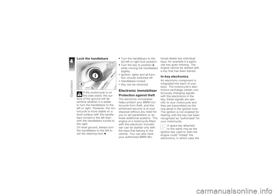
Lock the handlebars
If the motorcycle is on
the side stand, the sur-
face of the ground will de-
termine whether it is better
to turn the handlebars to the
left or right. However, the mo-
torcycle is more stable on a
level surface with the handle-
bars turned to the left than
with the handlebars turned to
the right.
On level ground, always turn
the handlebars to the left to
set the steering lock. Turn the handlebars to the
full left or right lock position.
Turn the key to position
3,
while moving the handlebars
slightly.
Ignition, lights and all func-
tion circuits switched off.
Handlebars locked.
Key can be removed.
Electronic immobiliserProtection against theftThe electronic immobiliser
helps protect your BMW mo-
torcycle from theft, and this
enhanced security is at your
disposal without any need for
you to set parameters or ac-
tivate additional systems. The
engine of a motorcycle fitted
with this electronic immobil-
iser can be started only with
the keys that belong to the
vehicle. You can also have
your authorised BMW Mo- torrad dealer bar individual
keys, for example if a partic-
ular key goes missing. The
engine cannot be started with
a key that has been barred.
In-key electronicsAn electronic component is
integrated into each of your
keys. The motorcycle's elec-
tronics exchange certain con-
tinuously changing signals
with the electronics in the
key; these signals are spe-
cific to your motorcycle and
they are transmitted via the
ring aerial in the ignition lock.
The ignition is not enabled for
starting until the key has been
recognised as "authorised" for
your motorcycle.
A spare key attached
to the same ring as the
ignition key used to start the
engine could "irritate" the
electronics, in which case the
444zOperation
Page 47 of 172
enabling signal for starting is
not issued. The
EWS
warning
appears in the multifunction
display.
Always keep the spare key
separately from the ignition
key.
Replacement and extra
keysYou can obtain replace-
ment/extra keys only through
an authorised BMW Motorrad
dealer. The keys are part
of an integrated security
system, so the dealer is under
an obligation to check the
legitimacy of all applications
for replacement/extra keys. If
you want to have a lost key
barred, you have to bring with
you all the other keys that
belong to the motorcycle. A
key that has been barred can
subsequently be cleared and
reactivated for use.
Hazard warning
flashersSwitch on the hazard
warning flashersSwitch on the ignition.
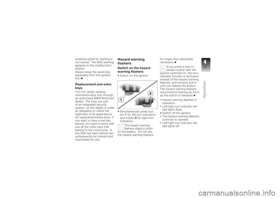
Simultaneously press but-
ton 1for left turn indicators
and button 2for right turn
indicators.
The hazard warning
flashers place a strain
on the battery. Do not use
the hazard warning flashers for longer than absolutely
necessary.
If you press a turn-in-
dicator button with the
ignition switched on, the turn-
indicator function is activated
instead of the hazard warning
flashers, and remains active
until you release the button.
The hazard warning flashers
recommence flashing as soon
as the button is released.
Hazard warning flashers in
operation.
Left/right turn indicator tell-
tale lights flash.
Switch off the ignition.
The hazard warning flashers
continue to operate.
Left/right turn indicator tell-
tale lights off.
445zOperation
Page 70 of 172
The seat engages with an
audible click.Helmet holderHelmet holder
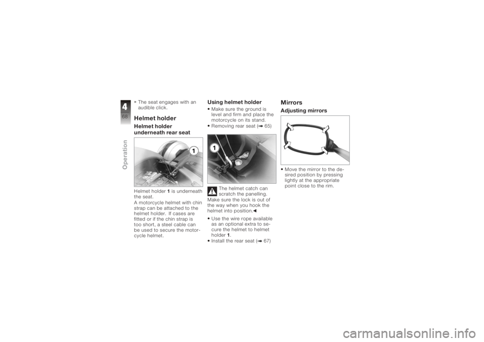
underneath rear seatHelmet holder1is underneath
the seat.
A motorcycle helmet with chin
strap can be attached to the
helmet holder. If cases are
fitted or if the chin strap is
too short, a steel cable can
be used to secure the motor-
cycle helmet.
Using helmet holderMake sure the ground is
level and firm and place the
motorcycle on its stand.
Removing rear seat ( 65)
The helmet catch can
scratch the panelling.
Make sure the lock is out of
the way when you hook the
helmet into position.
Use the wire rope available
as an optional extra to se-
cure the helmet to helmet
holder 1.
Install the rear seat ( 67)
MirrorsAdjusting mirrorsMove the mirror to the de-
sired position by pressing
lightly at the appropriate
point close to the rim.
468zOperation
Page 80 of 172
ponents are not designed to
withstand. Damage caused in
this way is not covered by the
warranty.
Do not tamper with the
control unit of the electronic
engine-management
system.ChecklistUse the following checklist
to check important functions,
settings and wear limits be-
fore you ride off.Brakes
Brake-fluid levels, front and
rear
Clutch
Clutch fluid level
Shock absorber setting and
spring preload
Tyre-tread depth and tyre
pressures Cases correctly installed
and luggage secured
At regular intervals: Engine oil level (every refuel-
ling stop)
StartingSide standYou cannot start the motor-
cycle with the side stand ex-
tended and a gear engaged.
The engine will switch itself off
if you start it with the gearbox
in neutral and then engage a
gear before retracting the side
stand.GearboxYou can start the engine
when the gearbox is in neutral
or if you pull the clutch with
a gear engaged. Do not pull
the clutch until after you have
switched on the ignition, as
otherwise the engine will refuse to start. When the
gearbox is in neutral, the
green neutral telltale light is
on and the gear indicator
in the multifunction display
shows N.
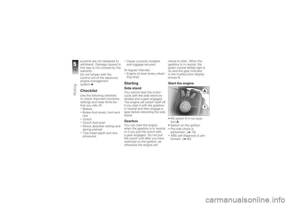
Start the engineKill switch
1in run posi-
tion A.
Switch on the ignition.
Pre-ride check is
performed. ( 79)
ABS self-diagnosis is per-
formed. ( 80)
578zRiding
Page 101 of 172
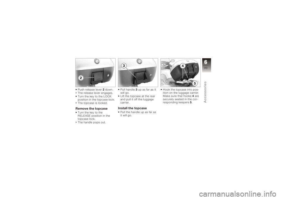
Push release lever2down.
The release lever engages.
Turn the key to the LOCK
position in the topcase lock.
The topcase is locked.Remove the topcaseTurn the key to the
RELEASE position in the
topcase lock.
The handle pops out. Pull handle
3up as far as it
will go.
Lift the topcase at the rear
and pull it off the luggage
carrier.
Install the topcasePull the handle up as far as
it will go. Hook the topcase into pos-
ition on the luggage carrier.
Make sure that hooks
4are
securely seated in the cor-
responding keepers 5.
699zAccessories
Page 102 of 172
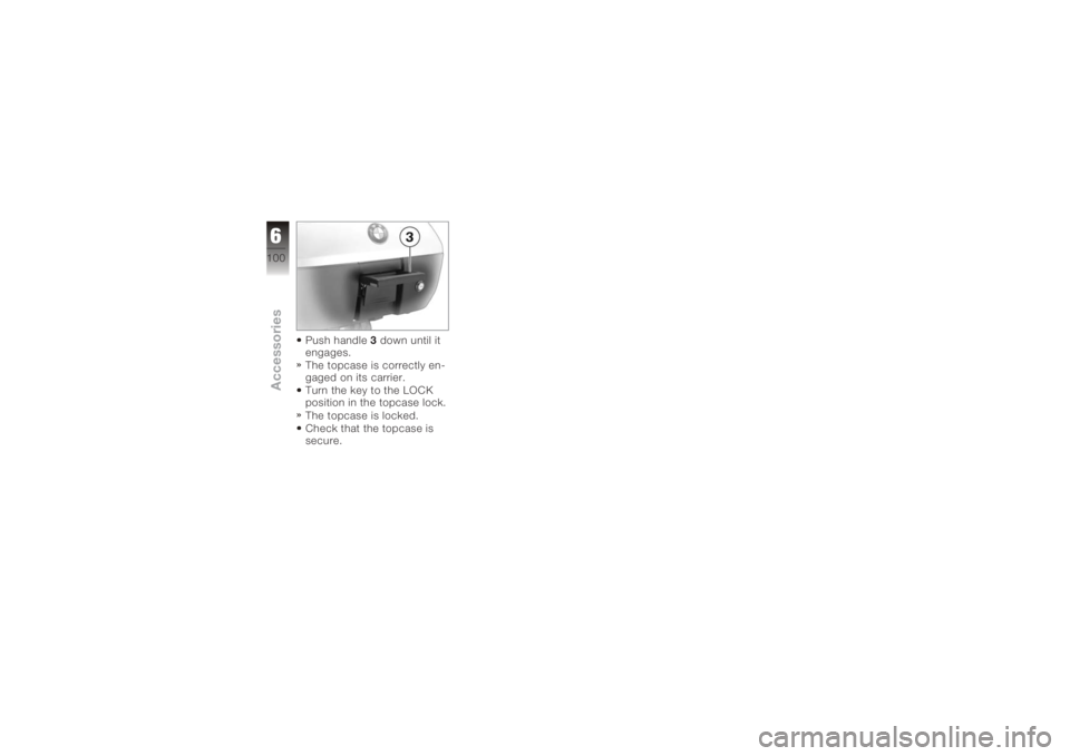
Push handle3down until it
engages.
The topcase is correctly en-
gaged on its carrier.
Turn the key to the LOCK
position in the topcase lock.
The topcase is locked.
Check that the topcase is
secure.
6100zAccessories
Page 113 of 172
draw the attention of the au-
thorised BMW Motorrad deal-
er or specialist workshop to
the fact that the wheel is fitted
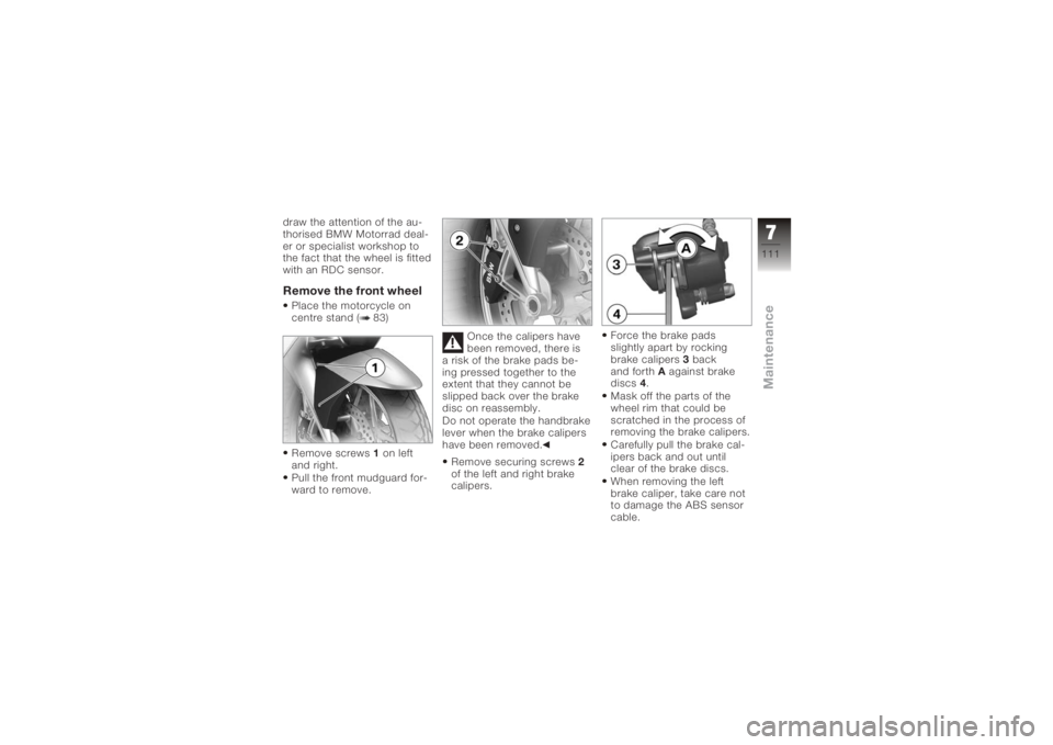
with an RDC sensor.Remove the front wheelPlace the motorcycle on
centre stand ( 83)
Remove screws1on left
and right.
Pull the front mudguard for-
ward to remove. Once the calipers have
been removed, there is
a risk of the brake pads be-
ing pressed together to the
extent that they cannot be
slipped back over the brake
disc on reassembly.
Do not operate the handbrake
lever when the brake calipers
have been removed.
Remove securing screws 2
of the left and right brake
calipers. Force the brake pads
slightly apart by rocking
brake calipers
3back
and forth Aagainst brake
discs 4.
Mask off the parts of the
wheel rim that could be
scratched in the process of
removing the brake calipers.
Carefully pull the brake cal-
ipers back and out until
clear of the brake discs.
When removing the left
brake caliper, take care not
to damage the ABS sensor
cable.
7111zMaintenance
Page 114 of 172
When removing the right
brake caliper, take care not
to alter the routing of the
sensor cable of the brake-
pad wear detector.
Raise the front of the mo-
torcycle until the front wheel
can rotate freely. BMW Mo-
torrad recommends the
BMW Motorrad front wheel
stand for lifting the motor-
cycle.
Fit the front-wheel stand
( 118)
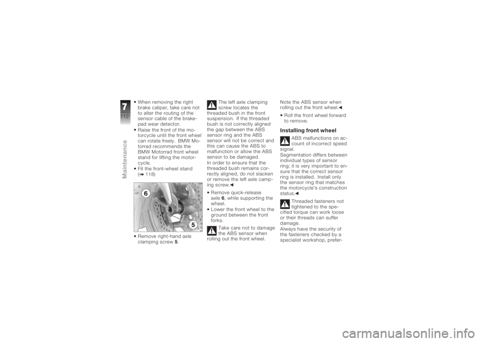
Remove right-hand axle
clamping screw5. The left axle clamping
screw locates the
threaded bush in the front
suspension. If the threaded
bush is not correctly aligned
the gap between the ABS
sensor ring and the ABS
sensor will not be correct and
this can cause the ABS to
malfunction or allow the ABS
sensor to be damaged.
In order to ensure that the
threaded bush remains cor-
rectly aligned, do not slacken
or remove the left axle camp-
ing screw.
Remove quick-release
axle 6, while supporting the
wheel.
Lower the front wheel to the
ground between the front
forks.
Take care not to damage
the ABS sensor when
rolling out the front wheel. Note the ABS sensor when
rolling out the front wheel.
Roll the front wheel forward
to remove.
Installing front wheel
ABS malfunctions on ac-
count of incorrect speed
signal.
Segmentation differs between
individual types of sensor
ring; it is very important to en-
sure that the correct sensor
ring is installed. Install only
the sensor ring that matches
the motorcycle's construction
status.
Threaded fasteners not
tightened to the spe-
cified torque can work loose
or their threads can suffer
damage.
Always have the security of
the fasteners checked by a
specialist workshop, prefer-
7112zMaintenance
Page 115 of 172
ably an authorised BMW Mo-
torrad dealer.The front wheel must be
installed right way round
to rotate in the correct direc-
tion.
Note the direction-of-rotation
arrows on the tyre or the
wheel rim.
There is a risk of dam-
aging parts of the front
brake, particularly the BMW
Motorrad Integral ABS, in the
course of the procedure de-
scribed below.
Take care not to damage the
brake system, in particular the
ABS sensor with cable and
the ABS sensor ring.
Take care not to damage
the ABS sensor when
rolling in the front wheel.
Note the ABS sensor when
rolling in the front wheel. Roll the front wheel into
position between the front
forks.
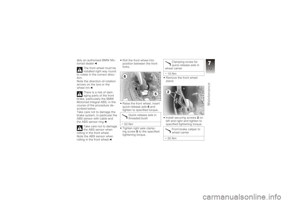
Raise the front wheel, insert
quick-release axle
6and
tighten to specified torque.
Quick-release axle in
threaded bush
50 Nm
Tighten right axle clamp-
ing screw 5to the specified
tightening torque. Clamping screw for
quick-release axle in
wheel carrier
19 Nm
Remove the front wheel
stand.
Install securing screws 2on
left and right and tighten to
specified tightening torque.
Front brake caliper to
wheel carrier
30 Nm
7113zMaintenance
Page 117 of 172
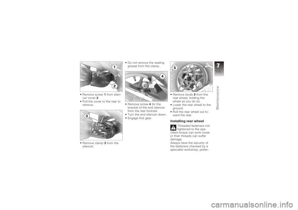
Remove screw1from silen-
cer cover 2.
Pull the cover to the rear to
remove.
Remove clamp 3from the
silencer. Do not remove the sealing
grease from the clamp.
Remove screw
4for the
bracket of the end silencer
from the rear footrest.
Turn the end silencer down.
Engage first gear. Remove studs
5from the
rear wheel, holding the
wheel as you do so.
Lower the rear wheel to the
ground.
Roll the rear wheel out to-
ward the rear.
Installing rear wheel
Threaded fasteners not
tightened to the spe-
cified torque can work loose
or their threads can suffer
damage.
Always have the security of
the fasteners checked by a
specialist workshop, prefer-
7115zMaintenance