battery BMW MOTORRAD K 1200 GT 2007 Rider's Manual (in English)
[x] Cancel search | Manufacturer: BMW MOTORRAD, Model Year: 2007, Model line: K 1200 GT, Model: BMW MOTORRAD K 1200 GT 2007Pages: 173, PDF Size: 2.82 MB
Page 45 of 173
Anti-theft alarm battery weakBattery symbol appears on
the display.DWA
appears on the display.
This error message appears
only briefly after the pre-
ride check completes.
The integral battery in the anti-
theft alarm has lost a significant
proportion of its original capa-
city. There is no assurance of
how long the anti-theft alarm can
remain operational if the motor-
cycle's battery is disconnected.
Seek the advice of a specialist
workshop, preferably an author-
ised BMW Motorrad dealer.
Anti-theft alarm battery flat General warning light shows
yellow.
Battery symbol appears on
the display.
DWA
appears on the display. This error message appears
only briefly after the pre-
ride check completes.
The integral battery in the anti-
theft alarm has lost its entire ori-
ginal capacity. There is no assur-
ance that the anti-theft alarm will
be operational if the motorcycle's
battery is disconnected.
Seek the advice of a specialist
workshop, preferably an author-
ised BMW Motorrad dealer.
343zStatus indicators
Page 49 of 173
Ignition switch and
steering lockKeysYou receive one master key and
one spare key. Please consult
the information on the electronic
immobiliser (EWS) if a key is lost
or mislaid ( 48).
Ignition switch and steering lock,
tank filler cap lock and the seat
and case locks are all operated
with the same key.
with OA Topcase:
If you wish you can arrange to
have the topcase fitted with a
lock that can be opened with this
key as well. Consult a specialist
workshop, preferably an author-
ised BMW Motorrad dealer.
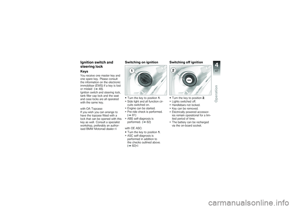
Switching on ignitionTurn the key to position1.
Side light and all function cir-
cuits switched on.
Engine can be started.
Pre-ride check is performed.
( 81)
ABS self-diagnosis is
performed. ( 82)
with OE ASC: Turn the key to position 1.
ASC self-diagnosis is
performed in addition to
the checks outlined above.
( 82)
Switching off ignitionTurn the key to position 2.
Lights switched off.
Handlebars not locked.
Key can be removed.
Electrically powered accessor-
ies remain operational for a lim-
ited period of time.
The battery can be recharged
via the on-board socket.
447zOperation
Page 57 of 173
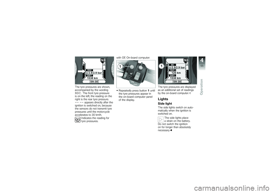
The tyre pressures are shown,
accompanied by the wordingRDC
. The front tyre pressure
is on the left; the reading on the
right is the rear tyre pressure.
-- --
appears directly after the
ignition is switched on, because
the sensors do not transmit tyre
pressures until the motorcycle
accelerates to 30 km/h.
Indicates the reading for
tyre pressures. with OE On-board computer:
Repeatedly press button 1until
the tyre pressures appear in
the on-board computer panel
of the display. The tyre pressures are displayed
as an additional set of readings
by the on-board computer.
LightsSide lightThe side lights switch on auto-
matically when the ignition is
switched on.
The side lights place
a strain on the battery.
Do not switch the ignition
on for longer than absolutely
necessary.
455zOperation
Page 59 of 173
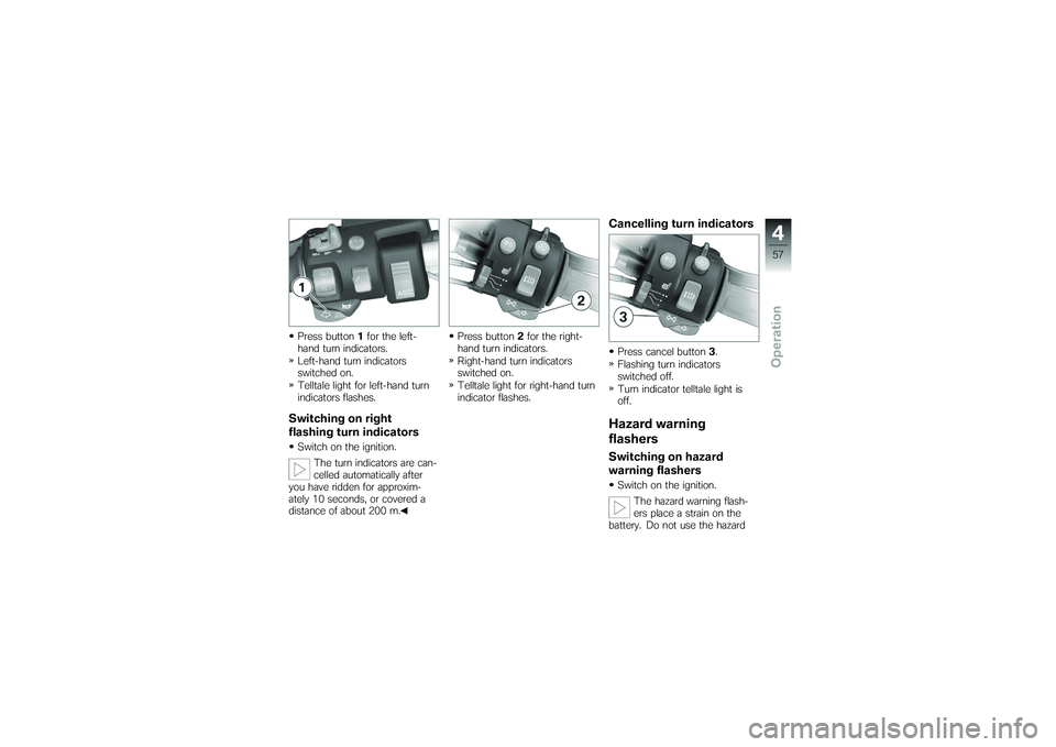
Press button1for the left-
hand turn indicators.
Left-hand turn indicators
switched on.
Telltale light for left-hand turn
indicators flashes.Switching on right
flashing turn indicatorsSwitch on the ignition.
The turn indicators are can-
celled automatically after
you have ridden for approxim-
ately 10 seconds, or covered a
distance of about 200 m. Press button
2for the right-
hand turn indicators.
Right-hand turn indicators
switched on.
Telltale light for right-hand turn
indicator flashes.
Cancelling turn indicatorsPress cancel button 3.
Flashing turn indicators
switched off.
Turn indicator telltale light is
off.Hazard warning
flashersSwitching on hazard
warning flashersSwitch on the ignition.
The hazard warning flash-
ers place a strain on the
battery. Do not use the hazard
457zOperation
Page 61 of 173

ANormal operating position
(run)
B Engine switched off.
You cannot start the engine
unless the kill switch is in
the run position.
Grip heating
OE
1 Grip heating switch
The handlebar grips have two-
stage heating. Grip heating can
be activated only when the en-
gine is running. The increase in power con-
sumption caused by the
grip heating can drain the bat-
tery if you are riding at low en-
gine speeds. If the charge level
is low, grip heating is switched
off to ensure the battery's start-
ing capability. 2
Heating off.
3 50 % heat output (one dot
visible)
4 100 % heat output (three
dots visible)
459zOperation
Page 62 of 173

Seat heating
OE
Seat heating, front seat1Switch for seat heating,
front seat
The front seat has two-stage
heating. Seat heating can be ac-
tivated only when the engine is
running. The increase in power con-
sumption caused by the
seat heating can drain the bat-
tery if you are riding at low en-
gine speeds. If the charge level
is low, seat heating is switched off to ensure the battery's start-
ing capability.
2
Heating off.
3 50% heating power
4 100% heating power
Seat heating, rear seat1Switch for seat heating, rear
seat
The rear seat has two-stage
heating. Seat heating can be ac-
tivated only when the engine is
running. The increase in power con-
sumption caused by the
seat heating can drain the bat-
tery if you are riding at low en-
gine speeds. If the charge level
is low, seat heating is switched
off to ensure the battery's start-
ing capability.
460zOperation
Page 83 of 173

ASC self-diagnosis is per-
formed. ( 82)
Press starter button1.
If ambient temperatures are
very low, you might find it
necessary to open the throttle
slightly when starting the engine.
At ambient temperatures below
0 °C, disengage the clutch after
switching on the ignition.
The start attempt is auto-
matically interrupted if bat-
tery voltage is too low. Recharge
the battery before you start the engine, or use jump leads and a
donor battery to start.
The engine starts.
Consult the troubleshooting
chart below if the engine re-
fuses to start. ( 142)
Pre-ride checkThe instrument cluster runs a
test of the 'General' warning light
when the ignition is switched
on: this is the "Pre-Ride-Check"
The warning light shows first red
and then yellow, so that you can
check that it is in working order.
The test is aborted if you start
the engine before it completes.
Phase 1 General warning light shows
red.CHECK!
appears on the dis-
play. Phase 2
General warning light shows
yellow.
CHECK!
appears on the dis-
play.
If the motorcycle is
equipped with cruise
control, SET lights up.
If the 'General' warning light does
not show:
Some malfunctions cannot
be indicated if the 'Gener-
al' warning light cannot be dis-
played.
Check that the 'General' warning
light comes on, and that it shows
red and yellow.
Have the fault rectified as
quickly as possible by a
specialist workshop, preferably
an authorised BMW Motorrad
dealer.
581zRiding
Page 100 of 173
General instructionsBMW Motorrad recommends
the use of parts and accessories
for your motorcycle that are ap-
proved by BMW for this purpose.
Genuine BMW parts and ac-
cessories and other products
which BMW has approved can
be obtained from your authorised
BMW Motorrad dealer, together
with expert advice on their install-
ation and use.
These parts and products have
been tested by BMW for safety,
function and suitability. BMW
accepts product liability for them.
Conversely, BMW is unable to
accept any liability whatsoever
for parts and accessories which it
has not approved.BMW Motorrad cannot
assess each non-BMW
product to determine wheth-
er it can be used on or in con-
nection with BMW motorcycles without constituting a safety haz-
ard. Country-specific official au-
thorisation does not suffice as
assurance. Tests conducted by
these instances cannot make
provision for all operating con-
ditions experienced by BMW mo-
torcycles and, consequently, they
are not sufficient in some circum-
stances.
Use only parts and accessor-
ies approved by BMW for your
motorcycle.
Whenever you are planning
modifications, comply with all
the legal requirements. Make
sure that the motorcycle does
not infringe national road-vehicle
construction and use regulations.
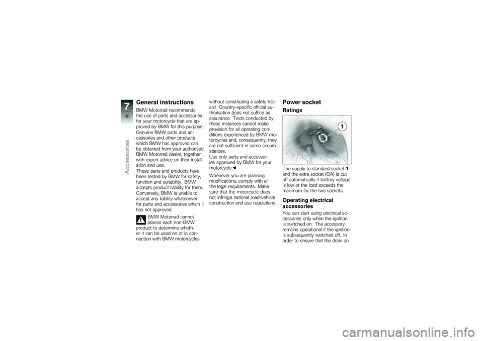
Power socketRatingsThe supply to standard socket
1
and the extra socket (OA) is cut
off automatically if battery voltage
is low or the load exceeds the
maximum for the two sockets.Operating electrical
accessoriesYou can start using electrical ac-
cessories only when the ignition
is switched on. The accessory
remains operational if the ignition
is subsequently switched off. In
order to ensure that the drain on
798zAccessories
Page 107 of 173
Maintenance
Maintenance
General instructions ................ 106
Toolkit . . . .......................... 106
Engine oil .......................... 107
Brake system, general . . . .......... 109
Brake pads . . . ..................... 109
Brake fluid ......................... 111
Clutch . . . .......................... 113
Tyres .............................. 113
Rims ............................... 114
Wheels . . .......................... 114
Front-wheel stand . . ............... 121
Bulbs .............................. 123
Jump starting . ..................... 131
Battery . . . .......................... 132
8105zMaintenance
Page 108 of 173
General instructionsThe Maintenance chapter de-
scribes straightforward proced-
ures for checking and replacing
certain wear parts.
Special tightening torques are lis-
ted as applicable. The tightening
torques for the threaded fasten-
ers on your motorcycle are listed
in the section entitled "Technical
data".
You will find information on more
extensive maintenance and re-
pair work in the Repair Manual
on DVD/CD-ROM (RepROM) for
your motorcycle, which is avail-
able from your authorised BMW
Motorrad dealer.
Some of the work calls for spe-
cial tools and a thorough know-
ledge of motorcycles. If you
are in doubt consult a specialist
workshop, preferably your author-
ised BMW Motorrad dealer.
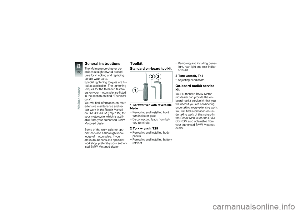
ToolkitStandard on-board toolkit1 Screwdriver with reversible
bladeRemoving and installing front
turn indicator glass
Disconnecting leads from bat-
tery terminals
2 Torx wrench, T25 Removing and installing body
panels
Removing and installing battery
retainer Removing and installing brake-
light, rear-light and rear-indicat-
or bulbs
3 Torx wrench, T45 Adjusting handlebars
On-board toolkit service
kitYour authorised BMW Motor-
rad dealer can provide the on-
board toolkit service kit that you
will need if you are considering
undertaking more extensive work.
You will find information on un-
dertaking work of this nature in
the Repair Manual on the DVD/
CD-ROM also obtainable from
your authorised BMW Motorrad
dealer.
8106zMaintenance