lock BMW MOTORRAD K 1200 GT 2007 Rider's Manual (in English)
[x] Cancel search | Manufacturer: BMW MOTORRAD, Model Year: 2007, Model line: K 1200 GT, Model: BMW MOTORRAD K 1200 GT 2007Pages: 173, PDF Size: 2.82 MB
Page 4 of 173
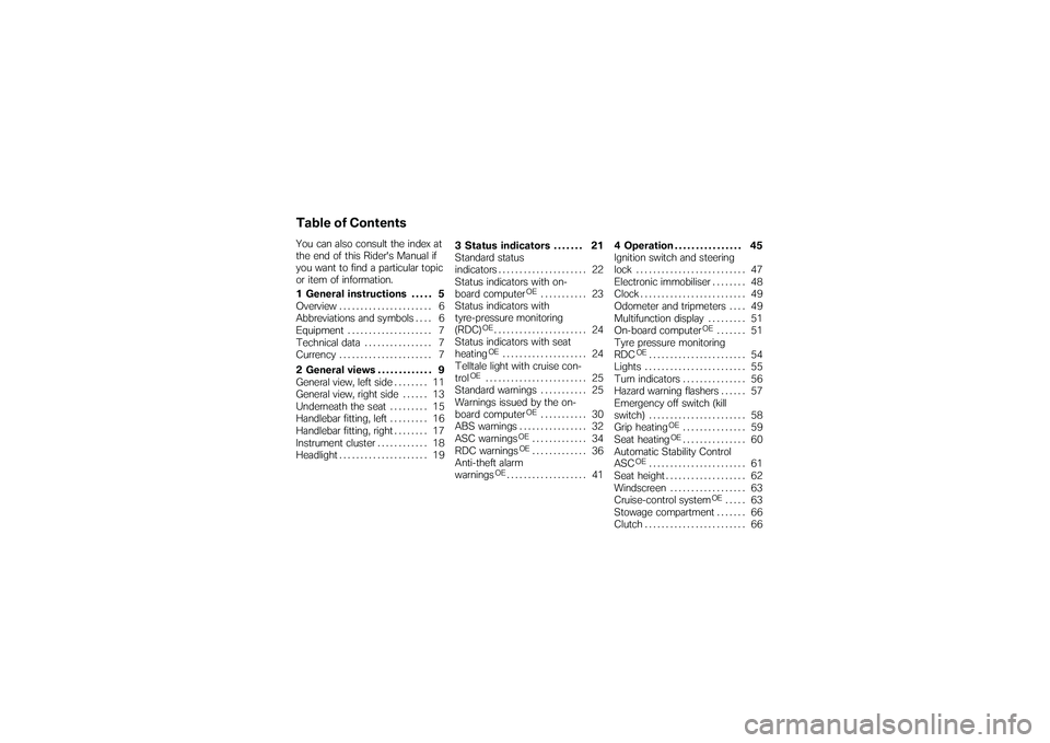
Table of ContentsYou can also consult the index at
the end of this Rider's Manual if
you want to find a particular topic
or item of information.
1 General instructions . . . . . 5
Overview ...................... 6
Abbreviations and symbols . . . . 6
Equipment . . . . . . .............. 7
Technical data . . .............. 7
Currency . ..................... 7
2 General views . . . . . . . . . . . . . 9
General view, left side . . . . . . . . 11
General view, right side . . . . . . 13
Underneath the seat ......... 15
Handlebar fitting, left ......... 16
Handlebar fitting, right . . . . . . . . 17
Instrument cluster . . . ......... 18
Headlight . .................... 19 3 Status indicators . . . . . . . 21
Standard status
indicators .
.................... 22
Status indicators with on-
board computer
OE
........... 23
Status indicators with
tyre-pressure monitoring
(RDC)
OE...................... 24
Status indicators with seat
heatingOE
.................... 24
Telltale light with cruise con-
trol
OE
........................ 25
Standard warnings . . ......... 25
Warnings issued by the on-
board computer
OE
........... 30
ABS warnings . . . ............. 32
ASC warnings
OE
............. 34
RDC warnings
OE
............. 36
Anti-theft alarm
warnings
OE................... 41 4 Operation . . . . . . . . . . . . . . . . 45
Ignition switch and steering
lock . .
........................ 47
Electronic immobiliser . . . . . . . . 48
Clock . . . . . .................... 49
Odometer and tripmeters . . . . 49
Multifunction display ......... 51
On-board computer
OE
....... 51
Tyre pressure monitoring
RDC
OE
....................... 54
Lights . . . . .................... 55
Turn indicators . . ............. 56
Hazard warning flashers . . . . . . 57
Emergency off switch (kill
switch) . . . .................... 58
Grip heating
OE
............... 59
Seat heatingOE............... 60
Automatic Stability Control
ASC
OE
....................... 61
Seat height . . . . . . ............. 62
Windscreen . . . . . ............. 63
Cruise-control system
OE
..... 63
Stowage compartment . . . . . . . 66
Clutch . . . . .................... 66
Page 8 of 173
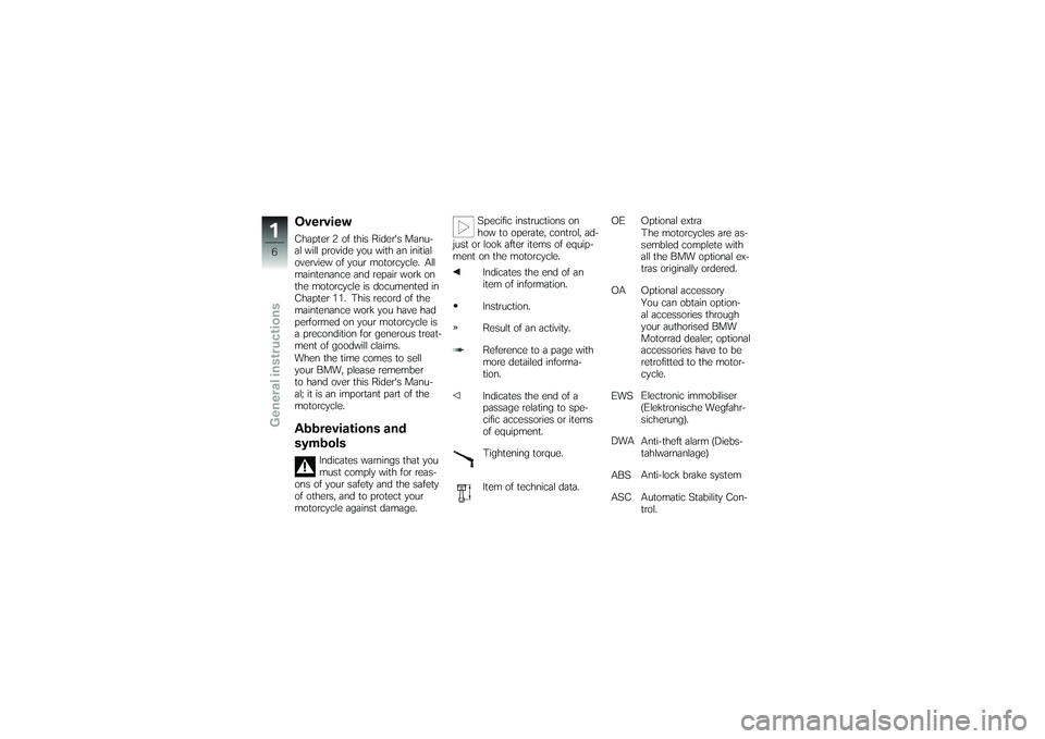
OverviewChapter 2 of this Rider's Manu-
al will provide you with an initial
overview of your motorcycle. All
maintenance and repair work on
the motorcycle is documented in
Chapter 11. This record of the
maintenance work you have had
performed on your motorcycle is
a precondition for generous treat-
ment of goodwill claims.
When the time comes to sell
your BMW, please remember
to hand over this Rider's Manu-
al; it is an important part of the
motorcycle.Abbreviations and
symbols
Indicates warnings that you
must comply with for reas-
ons of your safety and the safety
of others, and to protect your
motorcycle against damage. Specific instructions on
how to operate, control, ad-
just or look after items of equip-
ment on the motorcycle.
Indicates the end of an
item of information.
Instruction.
Result of an activity.
Reference to a page with
more detailed informa-
tion.
Indicates the end of a
passage relating to spe-
cific accessories or items
of equipment.
Tightening torque.
Item of technical data. OE Optional extra
The motorcycles are as-
sembled complete with
all the BMW optional ex-
tras originally ordered.
OA Optional accessory You can obtain option-
al accessories through
your authorised BMW
Motorrad dealer; optional
accessories have to be
retrofitted to the motor-
cycle.
EWS Electronic immobiliser
(Elektronische Wegfahr-
sicherung).
DWA Anti-theft alarm (Diebs-
tahlwarnanlage)
ABS Anti-lock brake system
ASC Automatic Stability Con- trol.
16zGeneral instructions
Page 13 of 173
General view, left side1Windscreen ( 63)
2 Battery compartment
( 134)
3 Seat lock (underneath the
rear light) ( 74)
4 Adjuster for spring preload,
rear ( 68)
5 Adjuster for damping char-
acteristic, rear suspension
( 69)
6 Power socket ( 98)
211zGeneral views
Page 20 of 173
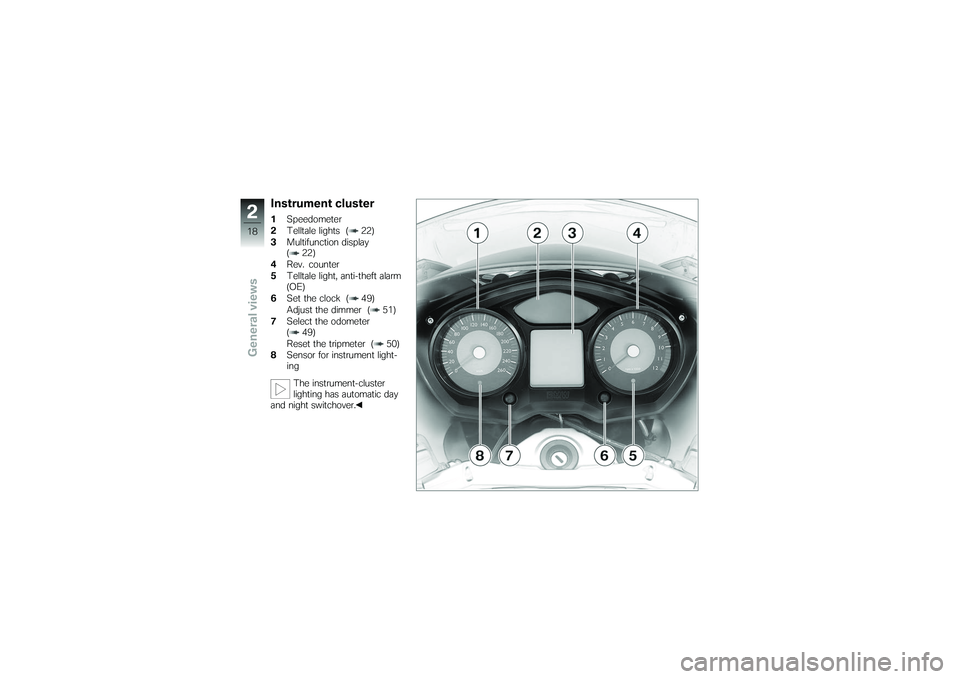
Instrument cluster1Speedometer
2 Telltale lights ( 22)
3 Multifunction display
( 22)
4 Rev. counter
5 Telltale light, anti-theft alarm
(OE)
6 Set the clock ( 49)
Adjust the dimmer ( 51)
7 Select the odometer
( 49)
Reset the tripmeter ( 50)
8 Sensor for instrument light-
ing
The instrument-cluster
lighting has automatic day
and night switchover.
218zGeneral views
Page 24 of 173
Standard status
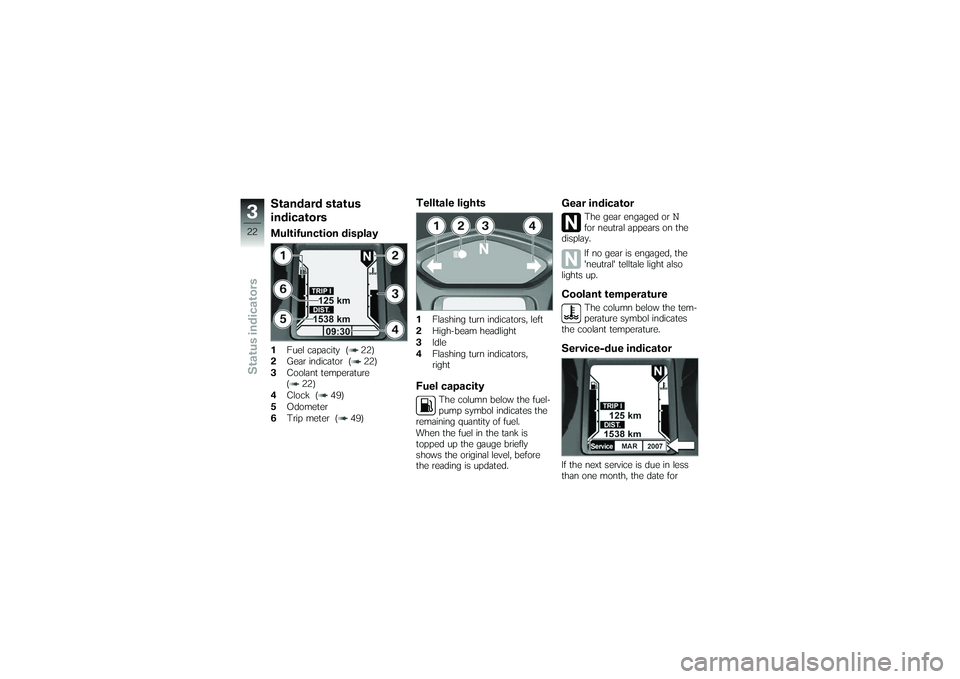
indicatorsMultifunction display1Fuel capacity ( 22)
2 Gear indicator ( 22)
3 Coolant temperature
( 22)
4 Clock ( 49)
5 Odometer
6 Trip meter ( 49)
Telltale lights1Flashing turn indicators, left
2 High-beam headlight
3 Idle
4 Flashing turn indicators,
rightFuel capacity
The column below the fuel-
pump symbol indicates the
remaining quantity of fuel.
When the fuel in the tank is
topped up the gauge briefly
shows the original level, before
the reading is updated.
Gear indicator
The gear engaged or
N
for neutral appears on the
display.
If no gear is engaged, the
'neutral' telltale light also
lights up.
Coolant temperature
The column below the tem-
perature symbol indicates
the coolant temperature.
Service-due indicatorIf the next service is due in less
than one month, the date for
322zStatus indicators
Page 47 of 173
Operation
Operation
Ignition switch and steering lock..... 47
Electronic immobiliser . . . ............ 48
Clock ................................ 49
Odometer and tripmeters ............ 49
Multifunction display ................. 51
On-board computer
OE
............... 51
Tyre pressure monitoring
RDC
OE
.............................. 54
Lights ................................ 55
Turn indicators ....................... 56
Hazard warning flashers . . ............ 57
Emergency off switch (kill switch) . . . . 58
Grip heating
OE
....................... 59
Seat heatingOE
...................... 60 Automatic Stability Control
ASC
OE
.............................. 61
Seat height . . . ....................... 62
Windscreen . . . ....................... 63
Cruise-control system
OE
............. 63
Stowage compartment . ............. 66
Clutch . . ............................. 66
Brakes . . ............................. 67
Handlebars . . . ....................... 67
Mirrors . . ............................. 68
Spring preload ....................... 68
Damping ............................. 69
Electronic Suspension Adjustment
ESA
OE
............................... 69
Tyres . . . ............................. 72
445zOperation
Page 49 of 173
Ignition switch and
steering lockKeysYou receive one master key and
one spare key. Please consult
the information on the electronic
immobiliser (EWS) if a key is lost
or mislaid ( 48).
Ignition switch and steering lock,
tank filler cap lock and the seat
and case locks are all operated
with the same key.
with OA Topcase:
If you wish you can arrange to
have the topcase fitted with a
lock that can be opened with this
key as well. Consult a specialist
workshop, preferably an author-
ised BMW Motorrad dealer.
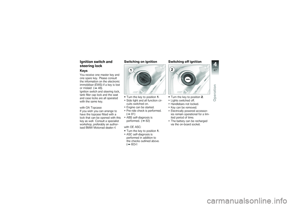
Switching on ignitionTurn the key to position1.
Side light and all function cir-
cuits switched on.
Engine can be started.
Pre-ride check is performed.
( 81)
ABS self-diagnosis is
performed. ( 82)
with OE ASC: Turn the key to position 1.
ASC self-diagnosis is
performed in addition to
the checks outlined above.
( 82)
Switching off ignitionTurn the key to position 2.
Lights switched off.
Handlebars not locked.
Key can be removed.
Electrically powered accessor-
ies remain operational for a lim-
ited period of time.
The battery can be recharged
via the on-board socket.
447zOperation
Page 50 of 173
Locking handlebars
If the motorcycle is on the
side stand, the surface of
the ground will determine wheth-
er it is better to turn the handle-
bars to the left or right. However,
the motorcycle is more stable on
a level surface with the handle-
bars turned to the left than with
the handlebars turned to the
right.
On level ground, always turn the
handlebars to the left to set the
steering lock.
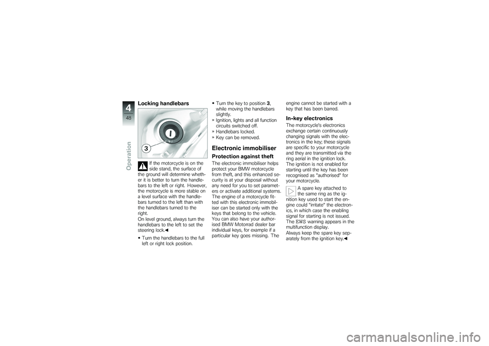
Turn the handlebars to the full
left or right lock position. Turn the key to position
3,
while moving the handlebars
slightly.
Ignition, lights and all function
circuits switched off.
Handlebars locked.
Key can be removed.
Electronic immobiliserProtection against theftThe electronic immobiliser helps
protect your BMW motorcycle
from theft, and this enhanced se-
curity is at your disposal without
any need for you to set paramet-
ers or activate additional systems.
The engine of a motorcycle fit-
ted with this electronic immobil-
iser can be started only with the
keys that belong to the vehicle.
You can also have your author-
ised BMW Motorrad dealer bar
individual keys, for example if a
particular key goes missing. The engine cannot be started with a
key that has been barred.
In-key electronicsThe motorcycle's electronics
exchange certain continuously
changing signals with the elec-
tronics in the key; these signals
are specific to your motorcycle
and they are transmitted via the
ring aerial in the ignition lock.
The ignition is not enabled for
starting until the key has been
recognised as "authorised" for
your motorcycle.
A spare key attached to
the same ring as the ig-
nition key used to start the en-
gine could "irritate" the electron-
ics, in which case the enabling
signal for starting is not issued.
The
EWS
warning appears in the
multifunction display.
Always keep the spare key sep-
arately from the ignition key.
448zOperation
Page 51 of 173
Replacement and extra
keysYou can obtain replacement/extra
keys only through an authorised
BMW Motorrad dealer. The keys
are part of an integrated secur-
ity system, so the dealer is un-
der an obligation to check the
legitimacy of all applications for
replacement/extra keys. If you
want to have a lost key barred,
you have to bring with you all
the other keys that belong to
the motorcycle. A key that has
been barred can subsequently be
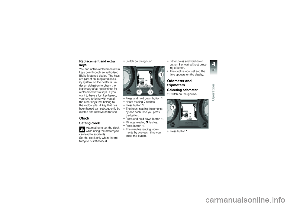
cleared and reactivated for use.ClockSetting clock
Attempting to set the clock
while riding the motorcycle
can lead to accidents.
Set the clock only when the mo-
torcycle is stationary. Switch on the ignition.
Press and hold down button
1.
Hours reading 2flashes.
Press button 1.
The hours reading increments
by one each time you press
the button.
Press and hold down button 1.
Minutes reading 3flashes.
Press button 1.
The minutes reading incre-
ments by one each time you
press the button. Either press and hold down
button
1or wait without press-
ing a button.
The clock is now set and the
time appears on the display.
Odometer and
tripmetersSelecting odometerSwitch on the ignition.
Press button 1.
449zOperation
Page 60 of 173
warning flashers for longer than
absolutely necessary.If you press a turn-indicat-
or button with the ignition
switched on, the turn-indicator
function is activated instead of
the hazard warning flashers, and
remains active until you release
the button. The hazard warning
flashers recommence flashing as
soon as the button is released.
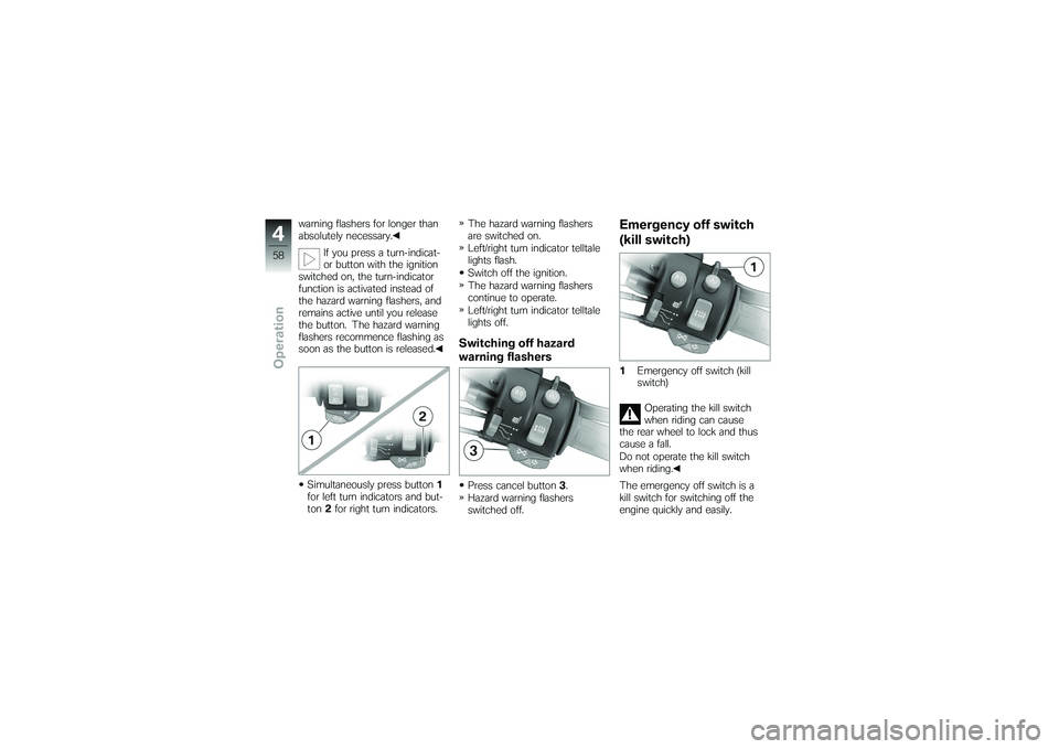
Simultaneously press button 1
for left turn indicators and but-
ton 2for right turn indicators. The hazard warning flashers
are switched on.
Left/right turn indicator telltale
lights flash.
Switch off the ignition.
The hazard warning flashers
continue to operate.
Left/right turn indicator telltale
lights off.
Switching off hazard
warning flashersPress cancel button
3.
Hazard warning flashers
switched off.
Emergency off switch
(kill switch)1 Emergency off switch (kill
switch)
Operating the kill switch
when riding can cause
the rear wheel to lock and thus
cause a fall.
Do not operate the kill switch
when riding.
The emergency off switch is a
kill switch for switching off the
engine quickly and easily.
458zOperation