lock BMW MOTORRAD K 1200 S 2004 Rider's Manual (in English)
[x] Cancel search | Manufacturer: BMW MOTORRAD, Model Year: 2004, Model line: K 1200 S, Model: BMW MOTORRAD K 1200 S 2004Pages: 162, PDF Size: 2.99 MB
Page 106 of 162
Maintenance6104
• Tighten aligning screws1.
• Press the front wheel stand
evenly downwards to raise
the motorcycle.
If the motorcycle is on the
centre stand
OA: If the
front of the motorcycle is
raised too far, the centre stand
rises from the ground and the
motorcycle can fall over
sideways.
When the front is raised, make
sure that the centre stand
remains on the ground.c
Rear wheel standIn order to be able to work
safely also on motorcycles
without centre stands
OA,
BMW Motorrad provides a rear
wheel stand. The rear wheel
stand with BMW special tool
number 36 3 980 can be
obtained from your authorised
BMW motorcycle dealer.
Mounting the rear wheel
stand
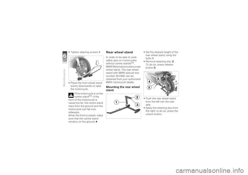
• Set the desired height of the
rear wheel stand using the
bolts 1.
• Remove retaining disc2.
To do so, press release
button3.
• Push the rear wheel stand
from the left into the rear
axle.
• Apply the retaining disc from
the right; to do so, press the
unlock button.
Page 108 of 162
Maintenance6106
Do not touch the glass of
new bulbs with your
fingers. Use a clean, dry cloth
when fitting. Dirt deposits, in
particular oil and grease,
interfere with heat radiation
from the bulb. This will result in
overheating and therefore
shorten the service life of the
bulbs.c
You will find an overview
of the types of screw
used on (
b 124).c
Replacing the low-beam
headlight bulb
During the work
described below, a
motorcycle that has been
parked unsafely can fall over.
Make sure that the motorcycle
is parked securely.cThe bulb is pressurised,
injuries may result if the
bulb is damaged.
Wear protective goggles and
gloves when changing
bulbs.c
To achieve better acces-
sibility, turn the handle-
bars to the right.c
• If necessary, switch off the
ignition.
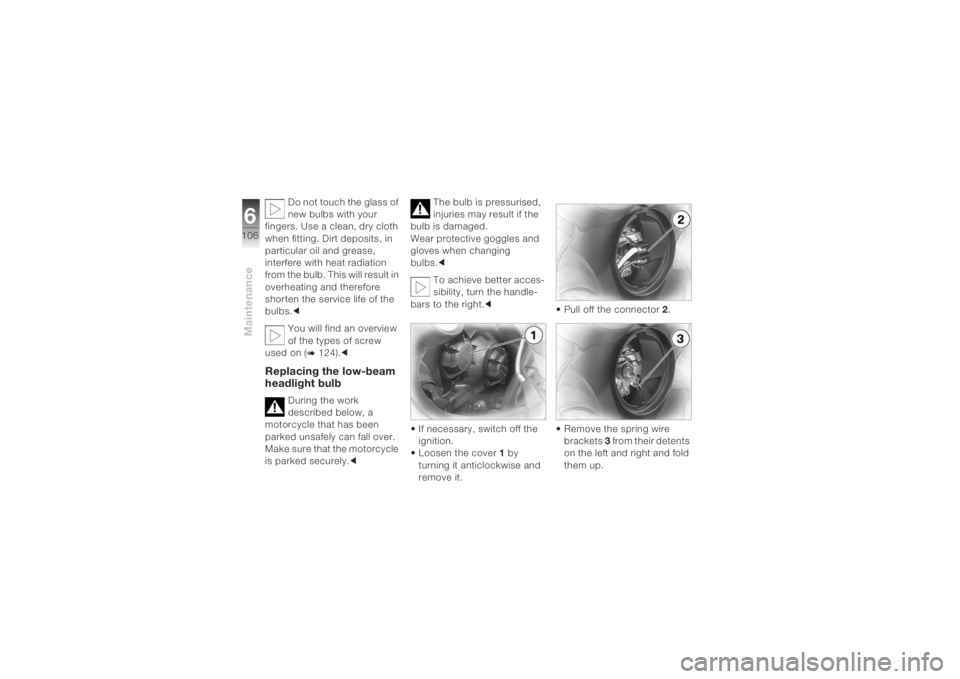
• Loosen the cover 1 by
turning it anticlockwise and
remove it.• Pull off the connector 2.
• Remove the spring wire
brackets 3 from their detents
on the left and right and fold
them up.
Page 110 of 162
Maintenance6108
Replacing the parking
light
During the work de-
scribed below, a motor-
cycle that has been parked
insecurely can fall over.
Make sure that the motorcycle
is parked securely.c
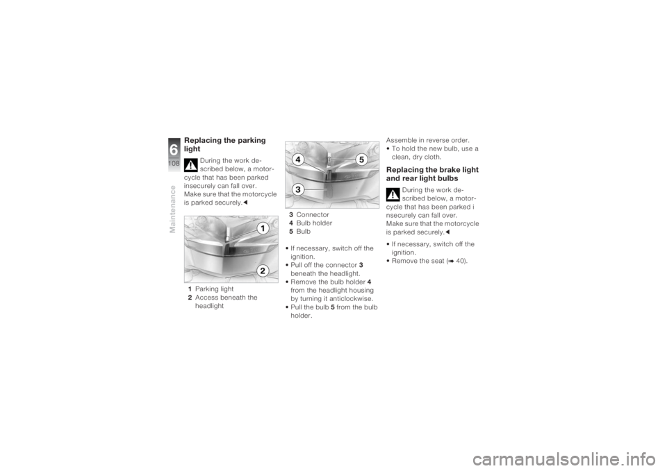
1Parking light
2Access beneath the
headlight3Connector
4Bulb holder
5Bulb
• If necessary, switch off the
ignition.
• Pull off the connector 3
beneath the headlight.
• Remove the bulb holder 4
from the headlight housing
by turning it anticlockwise.
• Pull the bulb 5 from the bulb
holder.Assemble in reverse order.
• To hold the new bulb, use a
clean, dry cloth.
Replacing the brake light
and rear light bulbs
During the work de-
scribed below, a motor-
cycle that has been parked i
nsecurely can fall over.
Make sure that the motorcycle
is parked securely.c
• If necessary, switch off the
ignition.
• Remove the seat (
b 40).
Page 111 of 162
6109
Maintenance
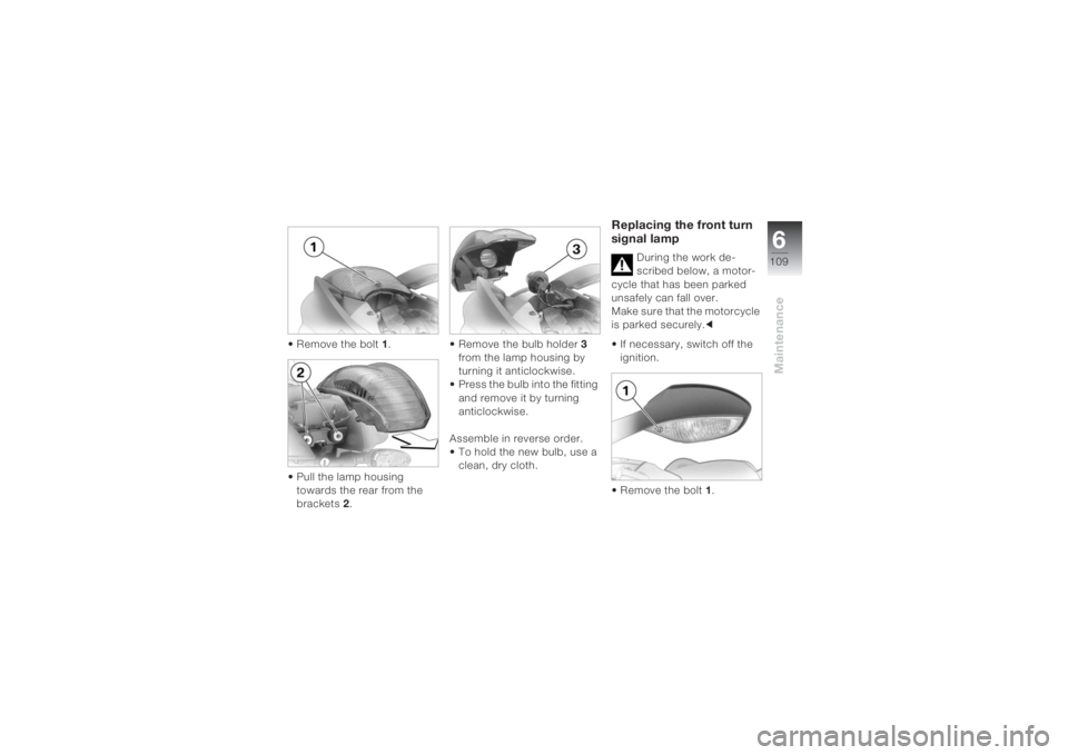
• Remove the bolt 1.
• Pull the lamp housing
towards the rear from the
brackets 2.• Remove the bulb holder 3
from the lamp housing by
turning it anticlockwise.
• Press the bulb into the fitting
and remove it by turning
anticlockwise.
Assemble in reverse order.
• To hold the new bulb, use a
clean, dry cloth.
Replacing the front turn
signal lamp
During the work de-
scribed below, a motor-
cycle that has been parked
unsafely can fall over.
Make sure that the motorcycle
is parked securely.c
• If necessary, switch off the
ignition.
• Remove the bolt 1.
Page 112 of 162
Maintenance6110
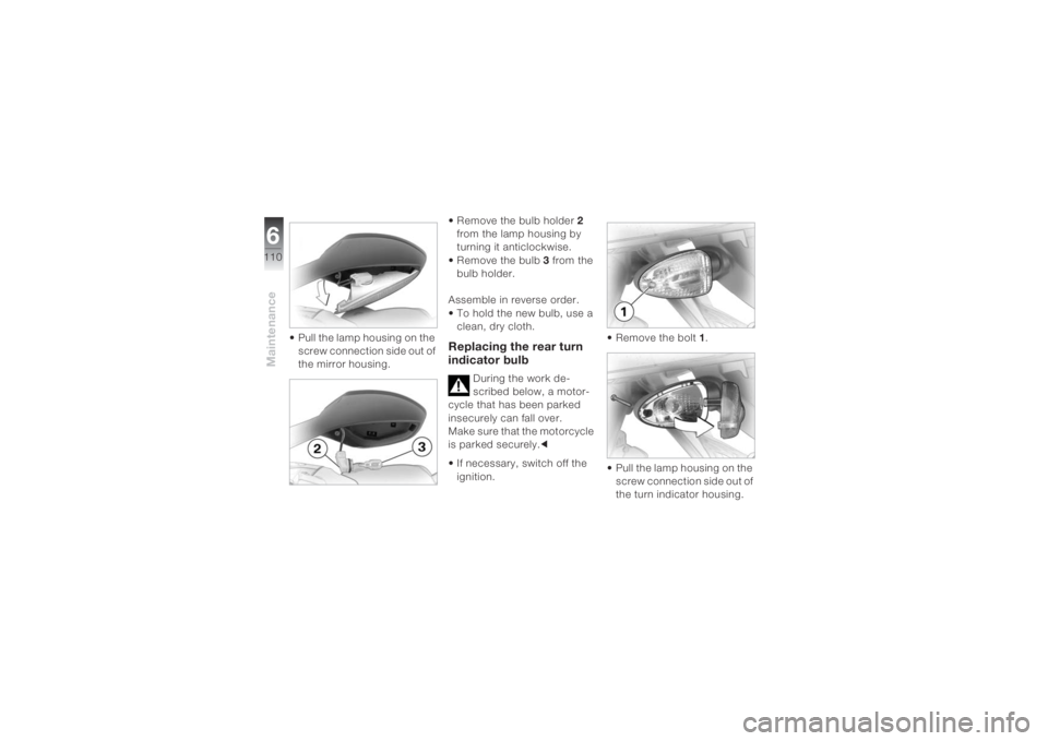
• Pull the lamp housing on the
screw connection side out of
the mirror housing.• Remove the bulb holder 2
from the lamp housing by
turning it anticlockwise.
• Remove the bulb 3 from the
bulb holder.
Assemble in reverse order.
• To hold the new bulb, use a
clean, dry cloth.
Replacing the rear turn
indicator bulb
During the work de-
scribed below, a motor-
cycle that has been parked
insecurely can fall over.
Make sure that the motorcycle
is parked securely.c
• If necessary, switch off the
ignition.• Remove the bolt 1.
• Pull the lamp housing on the
screw connection side out of
the turn indicator housing.
Page 113 of 162
6111
Maintenance
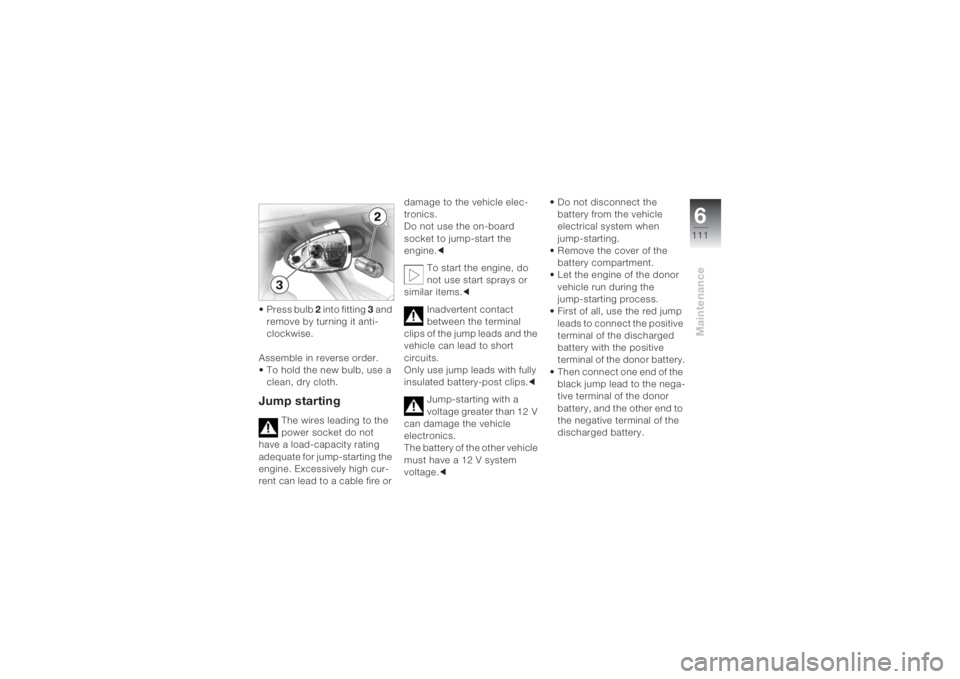
• Press bulb 2 into fitting 3 and
remove by turning it anti-
clockwise.
Assemble in reverse order.
• To hold the new bulb, use a
clean, dry cloth.Jump starting
The wires leading to the
power socket do not
have a load-capacity rating
adequate for jump-starting the
engine. Excessively high cur-
rent can lead to a cable fire or damage to the vehicle elec-
tronics.
Do not use the on-board
socket to jump-start the
engine.c
To start the engine, do
not use start sprays or
similar items.c
Inadvertent contact
between the terminal
clips of the jump leads and the
vehicle can lead to short
circuits.
Only use jump leads with fully
insulated battery-post clips.c
Jump-starting with a
voltage greater than 12 V
can damage the vehicle
electronics.
The battery of the other vehicle
must have a 12 V system
voltage.c• Do not disconnect the
battery from the vehicle
electrical system when
jump-starting.
• Remove the cover of the
battery compartment.
• Let the engine of the donor
vehicle run during the
jump-starting process.
• First of all, use the red jump
leads to connect the positive
terminal of the discharged
battery with the positive
terminal of the donor battery.
• Then connect one end of the
black jump lead to the nega-
tive terminal of the donor
battery, and the other end to
the negative terminal of the
discharged battery.
Page 114 of 162
Maintenance6112
• Start the engine of the
vehicle with the discharged
battery in the usual way; if
the engine does not start,
wait a few minutes before
repeating the attempt in
order to protect the starter
and the donor battery.
• Allow both engines to idle for
a few minutes before discon-
necting the jump leads.
• Disconnect the jump lead
from the negative terminals
first, then disconnect the
second lead from the
positive terminals.
• Screw down the cover of the
battery compartment.Touching live parts of the
ignition system with the
engine running can lead to
electric shocks.
Do not touch any parts of the
ignition system when the
engine is running.c
BatteryMaintenance informationYour motorcycle is supplied
with a maintenance-free
battery.
Correct upkeep, recharging
and storage will prolong the
life of the battery and are
essential if warranty claims are
to be considered.
Compliance with the points
below is important in order to
maximise battery life:– Keep the surface of the
battery clean and dry.
– Do not open the battery.
– Do not top up with water.
– Be sure to read and comply
with the instructions for
charging the battery on the
following pages.
– Do not turn the battery
upside down.
If the battery is not dis-
connected, the on-board
electronics (clock, etc.) will
drain the battery. This can
cause the battery to run flat.
If this happens, warranty
claims will not be accepted.
During immobilisation periods
of more than four weeks,
disconnect the battery from
the motorcycle or connect a
trickle charger to the battery.c
Page 116 of 162
Maintenance6114
If you are unable to
charge the battery via the
power socket, you may be
using a charger that is not
compatible with your motorcy-
cle’s electronics. In this case,
please charge the battery
directly at the terminals of the
disconnected battery.c
Charging the discon-
nected battery
In the case of longer
immobilisation periods,
the battery must be recharged
regularly.
In this connection, comply
with the instructions for the
battery. Always fully recharge
the battery before restoring it
to use.c• Charge the battery using a
suitable charger.
• Comply with the operating
instructions of the charger.
• Once the battery is fully
charged, disconnect the
charger terminal clips from
the battery terminals.
Removing the battery
You will find an overview
of the types of screw
used on (
b 125).c
During the work
described below, a
motorcycle that has been
parked unsafely can fall over.
Make sure that the motorcycle
is parked securely.c
• If necessary, switch off the
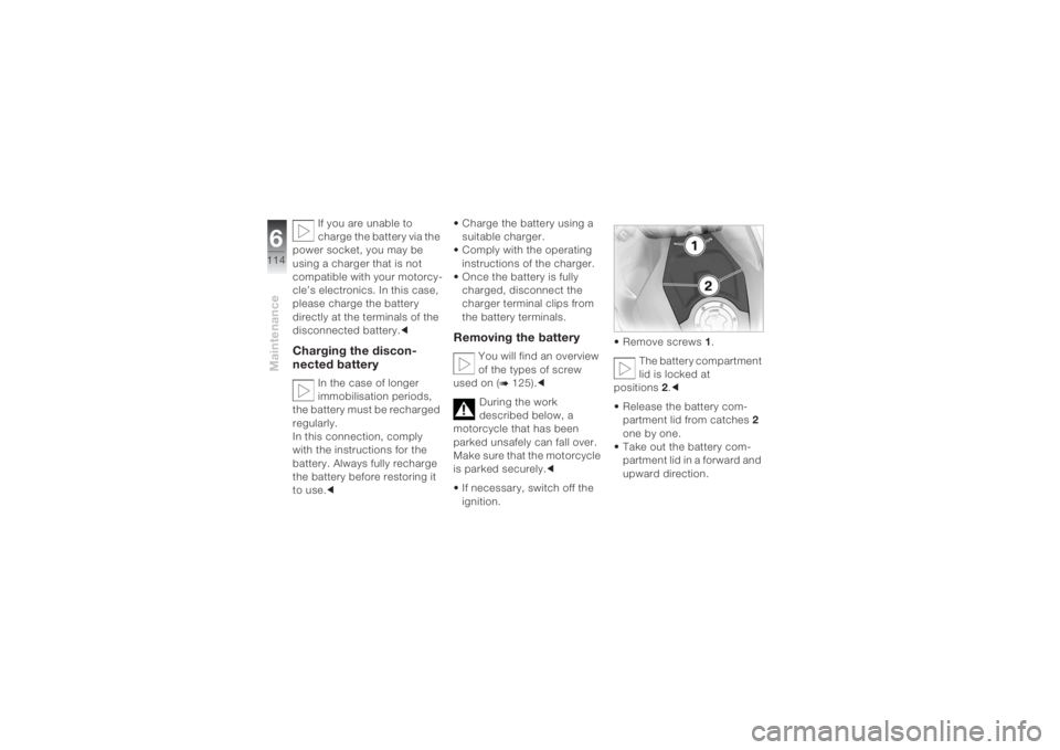
ignition.• Remove screws 1.
The battery compartment
lid is locked at
positions 2.c
• Release the battery com-
partment lid from catches 2
one by one.
• Take out the battery com-
partment lid in a forward and
upward direction.
Page 131 of 162
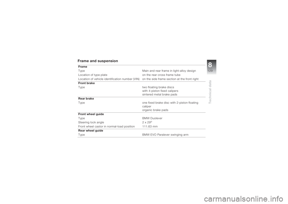
8129
Technical data
Frame and suspension Frame
Type Main and rear frame in light-alloy design
Location of type plate on the rear cross frame tube
Location of vehicle identification number (VIN) on the side frame section at the front right
Front brake
Type two floating brake discs
with 4-piston fixed calipers
sintered metal brake pads
Rear brake
Type one fixed brake disc with 2-piston floating
caliper
organic brake pads
Front wheel guide
Type BMW Duolever
Steering lock angle 2 x 29
o
Front wheel castor in normal-load position 111.63 mm
Rear wheel guide
Type BMW EVO Paralever swinging arm
Page 152 of 162
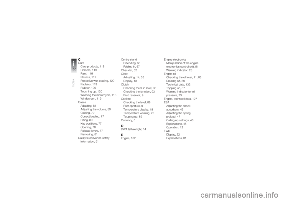
Indexi150
CCare
Care products, 118
Chrome, 119
Paint, 119
Plastics, 119
Protective wax coating, 120
Radiator, 119
Rubber, 120
Touching up, 120
Washing the motorcycle, 118
Windscreen, 119
Cases
Adapting, 81
Adjusting the volume, 80
Closing, 79
Correct loading, 77
Fitting, 80
Key positions, 77
Opening, 78
Release levers, 77
Removing, 81
Catalytic converter, safety
information, 51Centre stand
Extending, 65
Folding in, 67
Checklist, 52
Clock
Adjusting, 14, 35
Display, 18
Clutch
Checking the fluid level, 93
Checking the function, 93
Fluid reservoir, 9
Coolant
Checking the level, 88
Filler aperture, 9
Temperature display, 18
Temperature warning, 22
Topping up, 89
Currency, 5
DDWA telltale light, 14EEngine, 132Engine electronics
Manipulation of the engine
electronics control unit, 51
Warning indicator, 23
Engine oil
Checking the oil level, 11, 86
Draining off, 88
Technical data, 132
Topping up, 87
Warning indicator for oil
pressure, 23
Engine, technical data, 127
ESA
Adjusting the shock
absorbers, 46
Adjusting the spring
preload, 47
Calling up settings, 46
Explanations, 45
Operation, 12
EWS
Display, 22
Explanations, 31