wheel torque BMW MOTORRAD K 1200 S 2004 Rider's Manual (in English)
[x] Cancel search | Manufacturer: BMW MOTORRAD, Model Year: 2004, Model line: K 1200 S, Model: BMW MOTORRAD K 1200 S 2004Pages: 162, PDF Size: 2.99 MB
Page 99 of 162
697Maintenance
BMW Motorrad provides
an adapter for removing
the quick-release axle. This
adapter can be combined with
any commercially available
open-end or ring spanner with
width across flats 22. The
adapter with BMW special tool
number 36 3 690 can be ob-
tained from your authorised
BMW motorcycle dealer.c
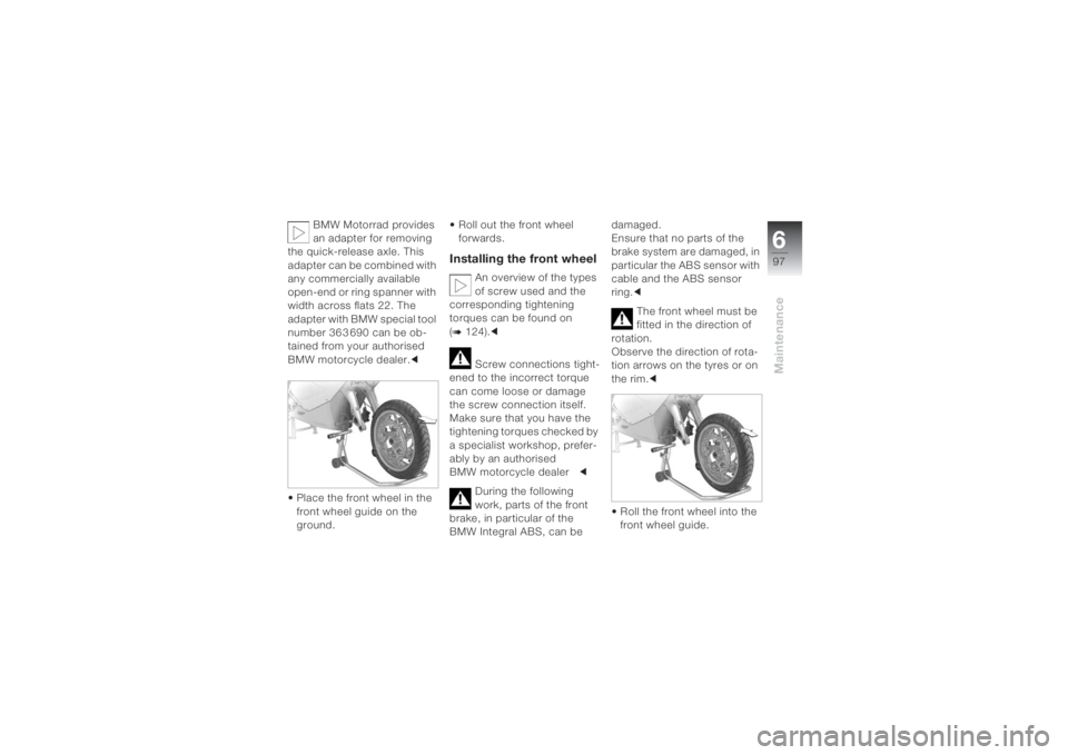
• Place the front wheel in the
front wheel guide on the
ground.• Roll out the front wheel
forwards.
Installing the front wheel
An overview of the types
of screw used and the
corresponding tightening
torques can be found on
(
b 124).c
Screw connections tight-
ened to the incorrect torque
can come loose or damage
the screw connection itself.
Make sure that you have the
tightening torques checked by
a specialist workshop, prefer-
ably by an authorised
BMW motorcycle dealerc
During the following
work, parts of the front
brake, in particular of the
BMW Integral ABS, can be damaged.
Ensure that no parts of the
brake system are damaged, in
particular the ABS sensor with
cable and the ABS sensor
ring.c
The front wheel must be
fitted in the direction of
rotation.
Observe the direction of rota-
tion arrows on the tyres or on
the rim.c
• Roll the front wheel into the
front wheel guide.
Page 100 of 162
Maintenance698
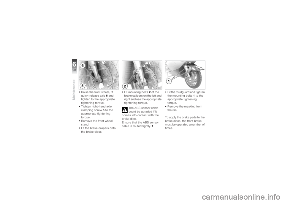
• Raise the front wheel, fit
quick-release axle 6 and
tighten to the appropriate
tightening torque.
• Tighten right-hand axle
clamping screw 5 to the
appropriate tightening
torque.
• Remove the front wheel
stand.
• Fit the brake calipers onto
the brake discs.• Fit mounting bolts 2 of the
brake calipers on the left and
right and use the appropriate
tightening torque.
The ABS sensor cable
could be abraded if it
comes into contact with the
brake disc.
Ensure that the ABS sensor
cable is routed tightly.c• Fit the mudguard and tighten
the mounting bolts1 to the
appropriate tightening
torque.
• Remove the masking from
the rim.
To apply the brake pads to the
brake discs, the front brake
must be operated a number of
times.
Page 102 of 162
Maintenance6100
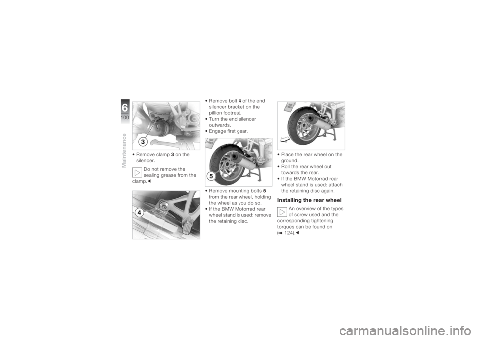
• Remove clamp3 on the
silencer.
Do not remove the
sealing grease from the
clamp.c• Remove bolt4 of the end
silencer bracket on the
pillion footrest.
• Turn the end silencer
outwards.
• Engage first gear.
• Remove mounting bolts5
from the rear wheel, holding
the wheel as you do so.
• If the BMW Motorrad rear
wheel stand is used: remove
the retaining disc.• Place the rear wheel on the
ground.
• Roll the rear wheel out
towards the rear.
• If the BMW Motorrad rear
wheel stand is used: attach
the retaining disc again.
Installing the rear wheel
An overview of the types
of screw used and the
corresponding tightening
torques can be found on
(
b 124).c
Page 103 of 162
6101
Maintenance
Screw connections tight-
ened to the incorrect
torque can come loose or
damage the screw connection
itself.
Make sure that you have the
tightening torques checked,
preferably by an authorised
BMW motorcycle dealer.c
• If the BMW Motorrad rear
wheel stand is used: remove
the retaining disc.• Roll the rear wheel onto the
rear wheel support.
• Place the rear wheel on the
rear wheel support.
• If the BMW Motorrad rear
wheel stand is used: attach
the retaining disc again.
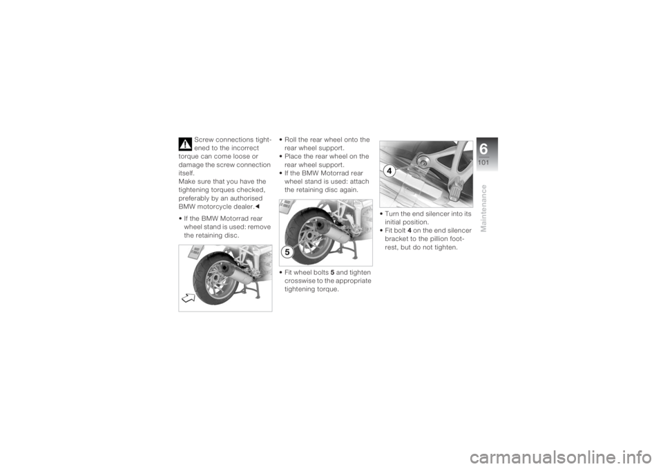
• Fit wheel bolts 5 and tighten
crosswise to the appropriate
tightening torque.• Turn the end silencer into its
initial position.
• Fit bolt4 on the end silencer
bracket to the pillion foot-
rest, but do not tighten.
Page 104 of 162
Maintenance6102
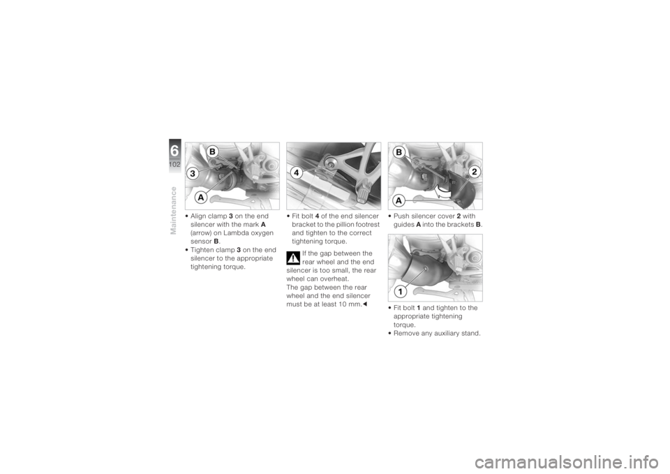
• Align clamp3 on the end
silencer with the markA
(arrow) on Lambda oxygen
sensor B.
• Tighten clamp3 on the end
silencer to the appropriate
tightening torque.• Fit bolt 4 of the end silencer
bracket to the pillion footrest
and tighten to the correct
tightening torque.
If the gap between the
rear wheel and the end
silencer is too small, the rear
wheel can overheat.
The gap between the rear
wheel and the end silencer
must be at least 10 mm.c• Push silencer cover 2 with
guides A into the brackets B.
• Fit bolt1 and tighten to the
appropriate tightening
torque.
• Remove any auxiliary stand.
Page 126 of 162
Technical data8124
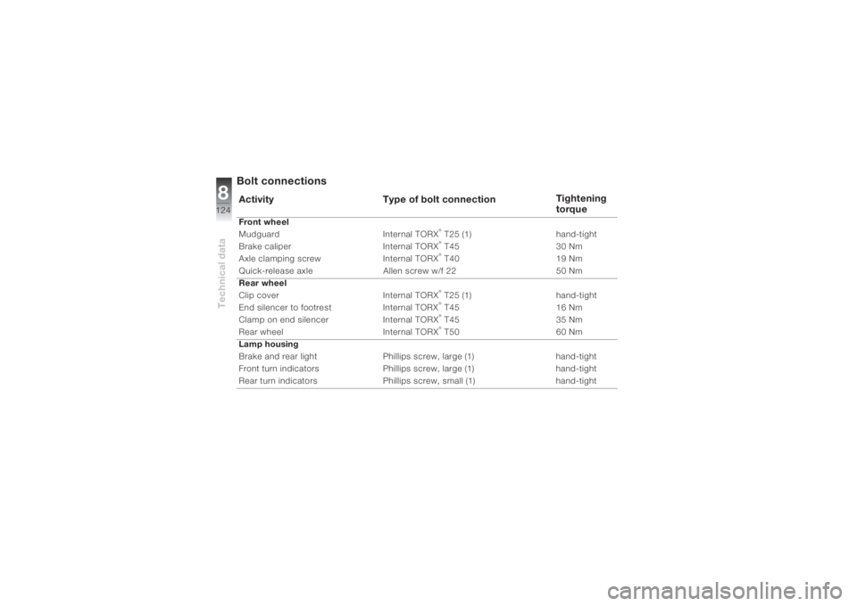
Bolt connections Activity Type of bolt connectionTightening
torqueFront wheel
Mudguard Internal TORX
® T25 (1) hand-tight
Brake caliper Internal TORX® T45 30 Nm
Axle clamping screw Internal TORX® T40 19 Nm
Quick-release axle Allen screw w/f 22 50 Nm
Rear wheel
Clip cover Internal TORX® T25 (1) hand-tight
End silencer to footrest Internal TORX® T45 16 Nm
Clamp on end silencer Internal TORX® T45 35 Nm
Rear wheel Internal TORX® T50 60 Nm
Lamp housing
Brake and rear light Phillips screw, large (1) hand-tight
Front turn indicators Phillips screw, large (1) hand-tight
Rear turn indicators Phillips screw, small (1) hand-tight
Page 155 of 162
i153
Index
Frame and suspension, 129
Fuel and lubricants, 132
Information, 5
Power transmission, 128
Riding specifications, 138
Wheels, 131
Telltale lights, 14, 18
Tightening torques, 124
Toolkit, 11, 85
Tripmaster, 12, 18, 33
Turn indicator
Left, 12
Replacing the front bulb, 109
Replacing the rear bulb, 110
Right, 13
Turn indicators
Switching off, 13, 40
Switching on, 39
Telltale lights, 18
Type plate, 11
VVehicle identification number, 11WWarning indicators
Notes, 19
Overview, 20
Warning lights, 14, 18
Warnings, 4
Wheels
Checking the rims, 94
Checking the tread depth, 94
Checking the tyre pressure, 47
Fitting the front wheel, 97
Fitting the rear wheel, 100
Makes, 94
Removing the front wheel, 95
Removing the rear wheel, 99
Technical data, 131
Tyre pressures, 126