check engine BMW X1 2014 E84 User Guide
[x] Cancel search | Manufacturer: BMW, Model Year: 2014, Model line: X1, Model: BMW X1 2014 E84Pages: 297, PDF Size: 7 MB
Page 109 of 297
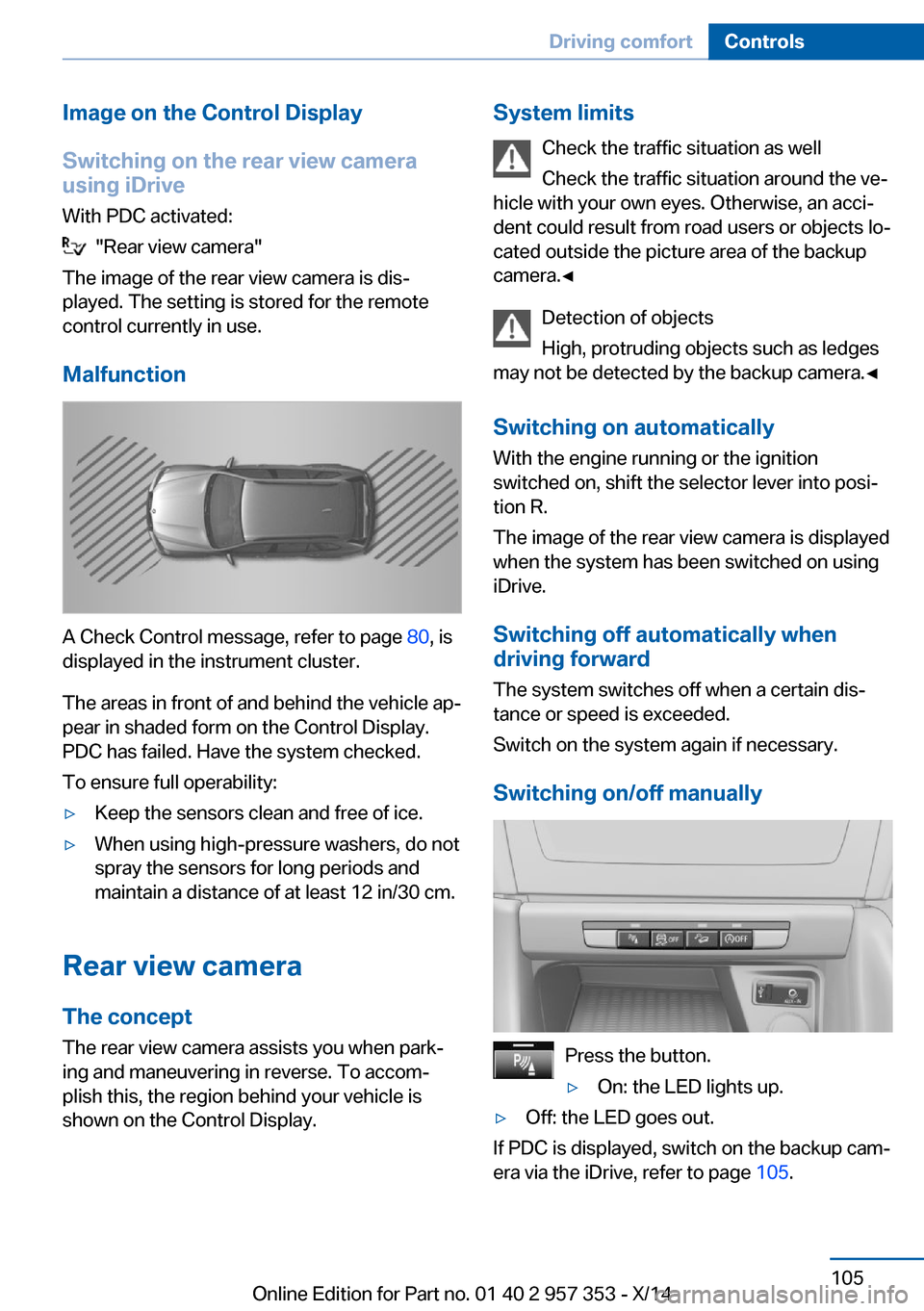
Image on the Control Display
Switching on the rear view camera
using iDrive
With PDC activated:
"Rear view camera"
The image of the rear view camera is disŌĆÉ
played. The setting is stored for the remote
control currently in use.
Malfunction
A Check Control message, refer to page 80, is
displayed in the instrument cluster.
The areas in front of and behind the vehicle apŌĆÉ
pear in shaded form on the Control Display.
PDC has failed. Have the system checked.
To ensure full operability:
Ō¢ĘKeep the sensors clean and free of ice.Ō¢ĘWhen using high-pressure washers, do not
spray the sensors for long periods and
maintain a distance of at least 12 in/30 cm.
Rear view camera
The concept The rear view camera assists you when parkŌĆÉ
ing and maneuvering in reverse. To accomŌĆÉ
plish this, the region behind your vehicle is
shown on the Control Display.
System limits
Check the traffic situation as well
Check the traffic situation around the veŌĆÉ
hicle with your own eyes. Otherwise, an acciŌĆÉ
dent could result from road users or objects loŌĆÉ
cated outside the picture area of the backup
camera.ŌŚĆ
Detection of objects
High, protruding objects such as ledges
may not be detected by the backup camera.ŌŚĆ
Switching on automatically With the engine running or the ignition
switched on, shift the selector lever into posiŌĆÉ
tion R.
The image of the rear view camera is displayed
when the system has been switched on using
iDrive.
Switching off automatically when
driving forward
The system switches off when a certain disŌĆÉ
tance or speed is exceeded.
Switch on the system again if necessary.
Switching on/off manually
Press the button.
Ō¢ĘOn: the LED lights up.Ō¢ĘOff: the LED goes out.
If PDC is displayed, switch on the backup camŌĆÉ
era via the iDrive, refer to page 105.
Seite 105Driving comfortControls105
Online Edition for Part no. 01 40 2 957 353 - X/14
Page 141 of 297
Saving fuelVehicle equipmentThis chapter describes all series equipment as
well as country-specific and special equipment
offered for this model series. Therefore, it also
describes equipment that may not be found in
your vehicle, for instance due to the selected
special equipment or the country version. This
also applies to safety-related functions and
systems.
When using the features and systems descriŌĆÉ
bed here, adhere to local regulations.
General information Your vehicle contains advanced technology for
the reduction of fuel consumption and emisŌĆÉ
sions.
Fuel consumption depends on a number of difŌĆÉ
ferent factors.
The implementation of certain measures, drivŌĆÉ
ing style and regular maintenance, refer to
page 245, can have an influence on fuel conŌĆÉ
sumption and on the environmental impact.
Remove unnecessary cargo
Additional weight increases fuel consumption.
Remove attached parts
following use
Remove unneeded auxiliary mirrors, roof or
rear luggage racks after use.
Attached parts on the vehicle impair the aeroŌĆÉ
dynamics and increase the fuel consumption.Closing the windows and
panoramic glass sunroof
Driving with the panoramic glass sunroof and
windows open results in increased air resistŌĆÉ
ance and raises fuel consumption.
Check the tire inflationpressure regularly
Check and, if necessary, correct the tire inflaŌĆÉ
tion pressure, refer to page 230, at least twice
a month and before starting on a long trip.
Low tire inflation pressure increases rolling reŌĆÉ
sistance and thus raises fuel consumption and
tire wear.
Drive away without delay
Do not wait for the engine to warm-up while
the vehicle remains stationary. Start driving
right away, but at moderate engine speeds.
This is the fastest way for the cold engine to
reach its operating temperature.
Look well ahead when
driving
Avoid unnecessary acceleration and braking.
By maintaining a suitable distance to the vehiŌĆÉ
cle driving ahead of you.
Driving smoothly and looking ahead reduces
fuel consumption.
Avoid high engine speeds
Driving at a low engine speed reduces fuel
consumption and minimizes wear.Seite 137Saving fuelDriving tips137
Online Edition for Part no. 01 40 2 957 353 - X/14
Page 245 of 297
Hood
Opening the hood Working in the engine compartment
Never attempt to perform any service or
repair operations on your vehicle without the necessary professional technical training.
If you are unfamiliar with the statutory guideŌĆÉ
lines, have any work on the vehicle performed
only by a service center.
If this work is not carried out properly, there is
the danger of subsequent damage and related
safety hazards.ŌŚĆ
Risk of damage
Before opening the hood, ensure that the
wiper arms with wiper blades are folded onto
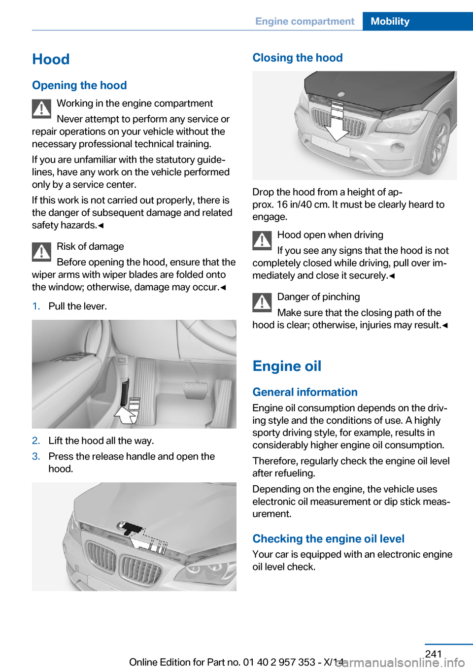
the window; otherwise, damage may occur.ŌŚĆ1.Pull the lever.2.Lift the hood all the way.3.Press the release handle and open the
hood.Closing the hood
Drop the hood from a height of apŌĆÉ
prox. 16 in/40 cm. It must be clearly heard to
engage.
Hood open when driving
If you see any signs that the hood is not
completely closed while driving, pull over imŌĆÉ
mediately and close it securely.ŌŚĆ
Danger of pinching
Make sure that the closing path of the
hood is clear; otherwise, injuries may result.ŌŚĆ
Engine oil
General information Engine oil consumption depends on the drivŌĆÉ
ing style and the conditions of use. A highly
sporty driving style, for example, results in
considerably higher engine oil consumption.
Therefore, regularly check the engine oil level
after refueling.
Depending on the engine, the vehicle uses
electronic oil measurement or dip stick measŌĆÉ
urement.
Checking the engine oil level Your car is equipped with an electronic engine
oil level check.
Seite 241Engine compartmentMobility241
Online Edition for Part no. 01 40 2 957 353 - X/14
Page 246 of 297
RequirementsŌ¢ĘThe engine must be running and warm afŌĆÉ
ter the vehicle has been driven for at least
6.2 miles/10 km.Ō¢ĘThe vehicle is stopped or being driven on a
level roadway.
Display in the instrument cluster
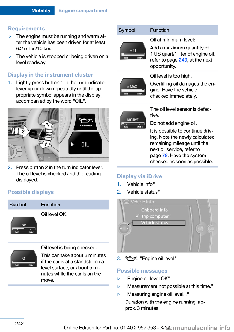
1.Lightly press button 1 in the turn indicator
lever up or down repeatedly until the apŌĆÉ
propriate symbol appears in the display,
accompanied by the word "OIL".2.Press button 2 in the turn indicator lever.
The oil level is checked and the reading
displayed.
Possible displays
SymbolFunctionOil level OK.Oil level is being checked.
This can take about 3 minutes
if the car is at a standstill on a
level surface, or about 5 miŌĆÉ
nutes while the car is on the
move.SymbolFunctionOil at minimum level:
Add a maximum quantity of
1 US quart/1 liter of engine oil,
refer to page 243, at the next
opportunity.Oil level is too high.
Overfilling oil damages the enŌĆÉ
gine. Have the vehicle
checked immediately.The oil level sensor is defecŌĆÉ
tive.
Do not add engine oil.
It is possible to continue drivŌĆÉ
ing. Note the newly calculated
remaining mileage until the
next oil service, refer to
page 78. Have the system
checked as soon as possible.
Display via iDrive
1."Vehicle Info"2."Vehicle status"3. "Engine oil level"
Possible messages
Ō¢Ę"Engine oil level OK"Ō¢Ę"Measurement not possible at this time."Ō¢Ę"Measuring engine oil level..."
Duration with the engine running: apŌĆÉ
prox. 3 minutes.Seite 242MobilityEngine compartment242
Online Edition for Part no. 01 40 2 957 353 - X/14
Page 247 of 297
Duration while driving: approx. 5 minutes.
If engine oil was added, it may take up to
30 minutes to obtain an oil level reading.Ō¢Ę"Engine oil level below minimum. Add 1
quart!"
Add a maximum quantity of 1 US quart/1 liŌĆÉ
ter of engine oil at the next opportunity, reŌĆÉ
fer also to Adding engine oil below.Ō¢Ę"Engine oil level too high! Have this
checked."
Too much engine oil
Have the vehicle checked immediŌĆÉ
ately; otherwise, surplus oil can lead to enŌĆÉ
gine damage.ŌŚĆŌ¢Ę"Measurement inactive. Have this
checked." Do not add engine oil. It is possiŌĆÉ
ble to continue driving. Note the newly calŌĆÉ
culated remaining mileage until the next oil
service, refer to page 78. Have the system
checked as soon as possible.
Adding engine oil
Filler neck
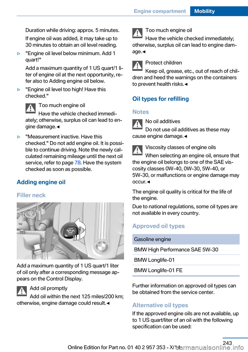
Add a maximum quantity of 1 US quart/1 liter
of oil only after a corresponding message apŌĆÉ
pears on the Control Display.
Add oil promptly
Add oil within the next 125 miles/200 km;
otherwise, engine damage could result.ŌŚĆ
Too much engine oil
Have the vehicle checked immediately;
otherwise, surplus oil can lead to engine damŌĆÉ
age.ŌŚĆ
Protect children
Keep oil, grease, etc., out of reach of chilŌĆÉ
dren and heed the warnings on the containers
to prevent health risks.ŌŚĆ
Oil types for refilling
Notes No oil additives
Do not use oil additives as these may
cause engine damage.ŌŚĆ
Viscosity classes of engine oils
When selecting an engine oil, ensure that
the engine oil belongs to one of the SAE visŌĆÉ
cosity classes 0W-40, 0W-30, 5W-40, or
5W-30, or malfunctions or engine damage may
occur.ŌŚĆ
The engine oil quality is critical for the life of
the engine.
Due to national regulations, some oil types are
not available in every country.
Approved oil typesGasoline engineBMW High Performance SAE 5W-30BMW Longlife-01BMW Longlife-01 FE
Further information on approved oil types can
be obtained from the service center.
Alternative oil types If the approved engine oils are not available, up
to 1 US quart/liter of an oil with the following
specification can be used:
Seite 243Engine compartmentMobility243
Online Edition for Part no. 01 40 2 957 353 - X/14
Page 248 of 297
Gasoline engineAPI SM or a higher quality standard
Oil changeThe manufacturer of your vehicle recommends
having the engine oil changed by a service
center.
Coolant General information Danger of burns from hot engine
Do not open the cooling system while
the engine is hot; otherwise, escaping coolant
may cause burns.ŌŚĆ
Suitable additives
Only use suitable additives; otherwise,
engine damage may occur. The additives are
harmful to your health.ŌŚĆ
Coolant consists of water and additives.
Not all commercially available additives are
suitable for your vehicle. Ask your service cenŌĆÉ
ter for suitable additives.
Checking the coolant level
1.Do not open the hood until the engine has
cooled down.2.Turn the expansion tank cap counterclockŌĆÉ
wise slightly to allow any accumulated
pressure to escape; then continue turning
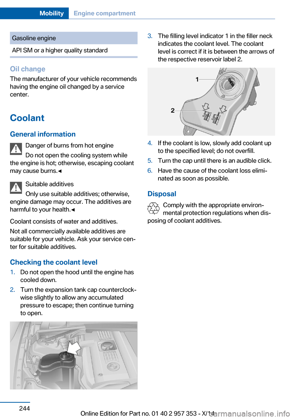
to open.3.The filling level indicator 1 in the filler neck
indicates the coolant level. The coolant
level is correct if it is between the arrows of
the respective reservoir label 2.4.If the coolant is low, slowly add coolant up
to the specified level; do not overfill.5.Turn the cap until there is an audible click.6.Have the cause of the coolant loss elimiŌĆÉ
nated as soon as possible.
Disposal
Comply with the appropriate environŌĆÉ
mental protection regulations when disŌĆÉ
posing of coolant additives.
Seite 244MobilityEngine compartment244
Online Edition for Part no. 01 40 2 957 353 - X/14
Page 249 of 297
MaintenanceVehicle equipment
This chapter describes all series equipment as
well as country-specific and special equipment
offered for this model series. Therefore, it also
describes equipment that may not be found in
your vehicle, for instance due to the selected
special equipment or the country version. This
also applies to safety-related functions and
systems.
When using the features and systems descriŌĆÉ
bed here, adhere to local regulations.
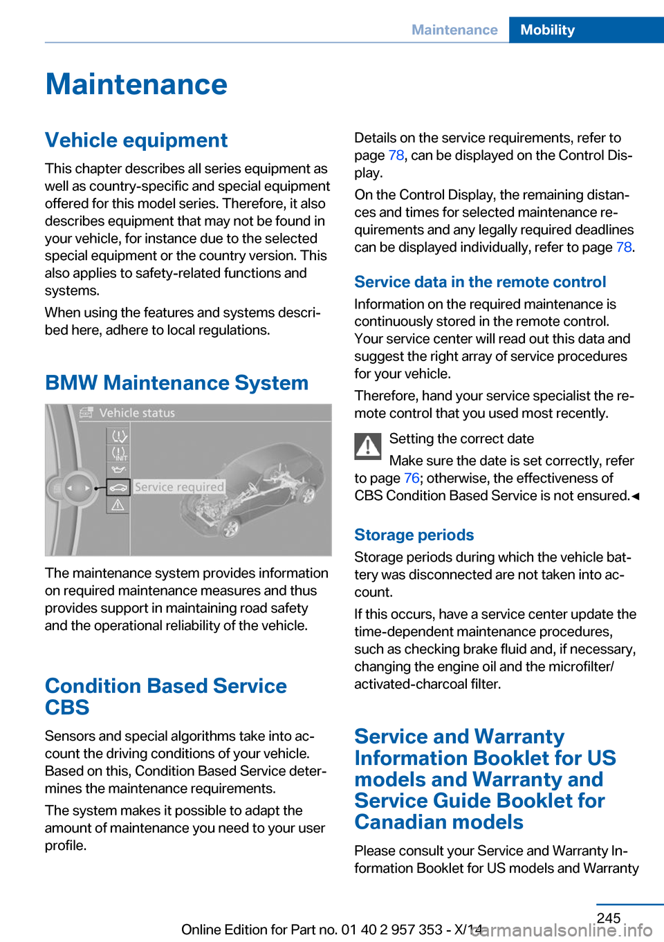
BMW Maintenance System
The maintenance system provides information
on required maintenance measures and thus
provides support in maintaining road safety
and the operational reliability of the vehicle.
Condition Based Service
CBS
Sensors and special algorithms take into acŌĆÉ
count the driving conditions of your vehicle.
Based on this, Condition Based Service deterŌĆÉ
mines the maintenance requirements.
The system makes it possible to adapt the
amount of maintenance you need to your user
profile.
Details on the service requirements, refer to
page 78, can be displayed on the Control DisŌĆÉ
play.
On the Control Display, the remaining distanŌĆÉ
ces and times for selected maintenance reŌĆÉ
quirements and any legally required deadlines
can be displayed individually, refer to page 78.
Service data in the remote control Information on the required maintenance is
continuously stored in the remote control. Your service center will read out this data and
suggest the right array of service procedures
for your vehicle.
Therefore, hand your service specialist the reŌĆÉ
mote control that you used most recently.
Setting the correct date
Make sure the date is set correctly, refer
to page 76; otherwise, the effectiveness of
CBS Condition Based Service is not ensured.ŌŚĆ
Storage periods Storage periods during which the vehicle batŌĆÉ
tery was disconnected are not taken into acŌĆÉ
count.
If this occurs, have a service center update the
time-dependent maintenance procedures,
such as checking brake fluid and, if necessary,
changing the engine oil and the microfilter/
activated-charcoal filter.
Service and Warranty
Information Booklet for US
models and Warranty and
Service Guide Booklet for Canadian models
Please consult your Service and Warranty InŌĆÉ
formation Booklet for US models and WarrantySeite 245MaintenanceMobility245
Online Edition for Part no. 01 40 2 957 353 - X/14
Page 250 of 297
and Service Guide Booklet for Canadian modŌĆÉ
els for additional information on service reŌĆÉ
quirements.
Maintenance and repair should be performed
by your service center. Make sure to have regŌĆÉ
ular maintenance procedures recorded in the
vehicle's Service and Warranty Information
Booklet for US models, and in the Warranty
and Service Guide Booklet for Canadian modŌĆÉ
els. These entries are proof of regular mainteŌĆÉ
nance.
Socket for OBD Onboard
Diagnosis
Socket for Onboard Diagnosis
The socket for Onboard Diagnosis may
only be used by the service center, by workŌĆÉ
shops that operate according to the specificaŌĆÉ
tions of the vehicle manufacturer with approŌĆÉ
priately trained personnel, and by other
authorized persons. Otherwise, its use may
lead to vehicle malfunctions.ŌŚĆ
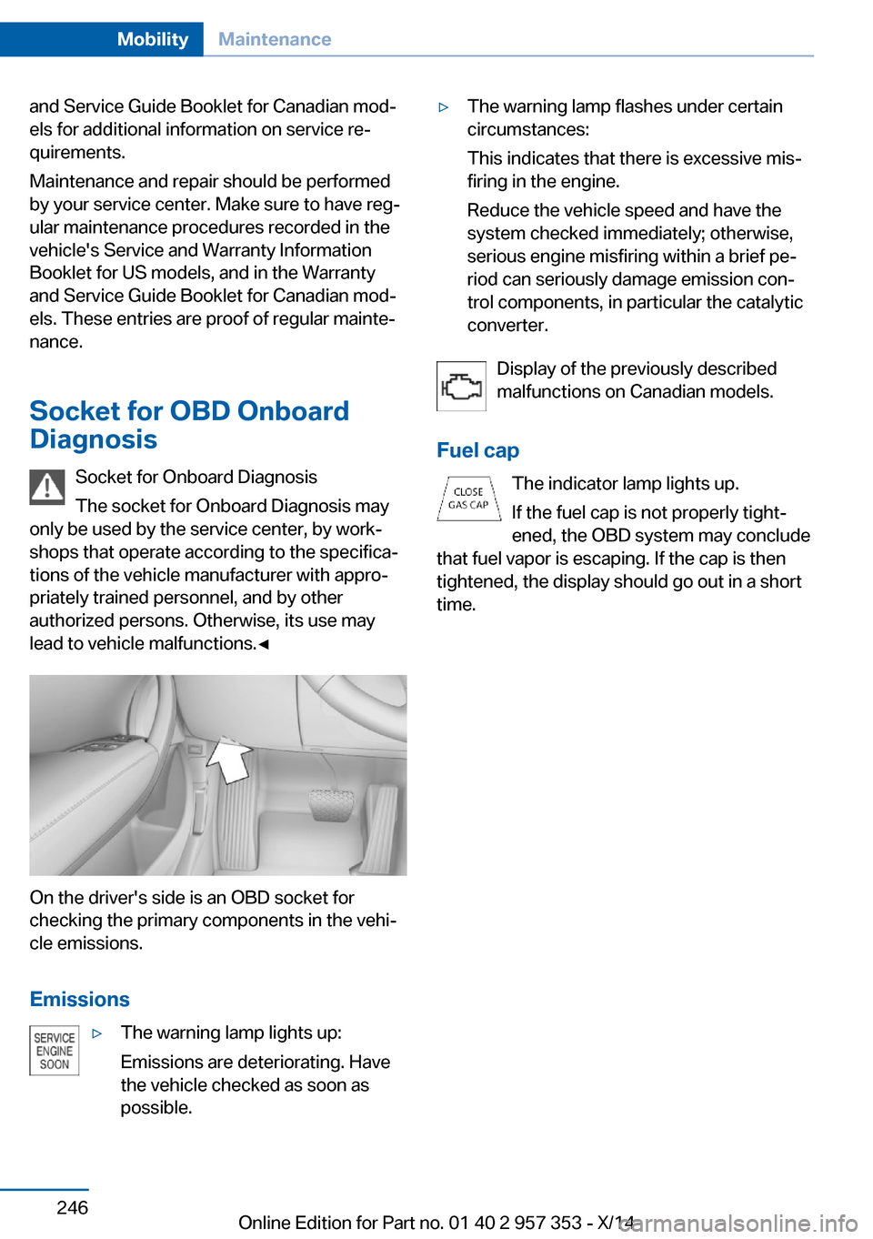
On the driver's side is an OBD socket for
checking the primary components in the vehiŌĆÉ
cle emissions.
Emissions
Ō¢ĘThe warning lamp lights up:
Emissions are deteriorating. Have
the vehicle checked as soon as
possible.Ō¢ĘThe warning lamp flashes under certain
circumstances:
This indicates that there is excessive misŌĆÉ
firing in the engine.
Reduce the vehicle speed and have the
system checked immediately; otherwise,
serious engine misfiring within a brief peŌĆÉ
riod can seriously damage emission conŌĆÉ
trol components, in particular the catalytic
converter.
Display of the previously described
malfunctions on Canadian models.
Fuel cap The indicator lamp lights up.
If the fuel cap is not properly tightŌĆÉ
ened, the OBD system may conclude
that fuel vapor is escaping. If the cap is then
tightened, the display should go out in a short
time.
Seite 246MobilityMaintenance246
Online Edition for Part no. 01 40 2 957 353 - X/14
Page 253 of 297
Headlight setting
Changing the bulbs and lights may influence
the headlight settings. Have the headlight setŌĆÉ
ting checked by a service center and corrected
if necessary after changing bulbs or lights.
Removing the headlamp cover
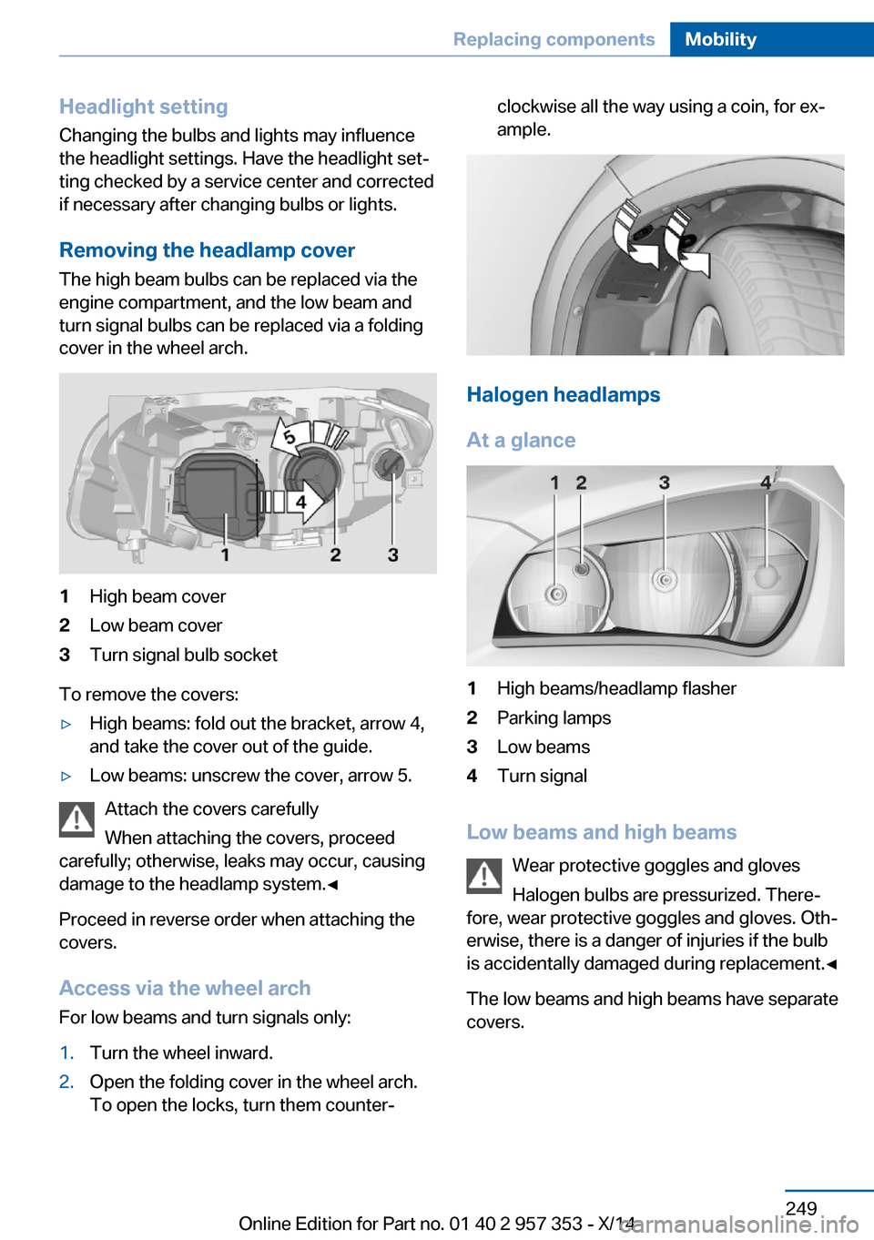
The high beam bulbs can be replaced via the
engine compartment, and the low beam and
turn signal bulbs can be replaced via a folding
cover in the wheel arch.1High beam cover2Low beam cover3Turn signal bulb socket
To remove the covers:
Ō¢ĘHigh beams: fold out the bracket, arrow 4,
and take the cover out of the guide.Ō¢ĘLow beams: unscrew the cover, arrow 5.
Attach the covers carefully
When attaching the covers, proceed
carefully; otherwise, leaks may occur, causing
damage to the headlamp system.ŌŚĆ
Proceed in reverse order when attaching the
covers.
Access via the wheel arch For low beams and turn signals only:
1.Turn the wheel inward.2.Open the folding cover in the wheel arch.
To open the locks, turn them counterŌĆÉclockwise all the way using a coin, for exŌĆÉ
ample.
Halogen headlamps
At a glance
1High beams/headlamp flasher2Parking lamps3Low beams4Turn signal
Low beams and high beams Wear protective goggles and gloves
Halogen bulbs are pressurized. ThereŌĆÉ
fore, wear protective goggles and gloves. OthŌĆÉ
erwise, there is a danger of injuries if the bulb
is accidentally damaged during replacement.ŌŚĆ
The low beams and high beams have separate
covers.
Seite 249Replacing componentsMobility249
Online Edition for Part no. 01 40 2 957 353 - X/14
Page 258 of 297
General information
Ensure that the battery is sufficiently charged
to achieve the full battery life.
It may be necessary to charge the battery in
the following cases:Ō¢ĘWhen the vehicle is frequently used to
drive short distances.Ō¢ĘWhen the vehicle has not been driven for
more than one month.
Starting aid terminals
Only charge using the starting aid terminals,
refer to page 257, in the engine compartment
while the engine is switched off.
Power failure
After a temporary power loss, some equipment
needs to be reinitialized.
Individual settings need to be reprogrammed:
Ō¢ĘSeat and mirror memory: store the posiŌĆÉ
tions again, refer to page 48.Ō¢ĘTime: update, refer to page 75.Ō¢ĘDate: update, refer to page 76.Ō¢ĘRadio station: save again, refer to
page 166.Ō¢ĘNavigation system: wait for the navigation
system to be operational.Ō¢ĘPanoramic glass sunroof: it may only be
possible to tilt the roof. Have the system
initialized by the service center.Ō¢ĘDigital compass: recalibrate, refer to
page 115.Ō¢ĘxDrive: the system automatically initializes
as you drive. During this time, indicator
lamps light up. If the lamps do not disapŌĆÉ
pear during the current trip, have the sysŌĆÉ
tem checked.
Disposing of old batteries
Have old batteries disposed of by your
service center or bring them to a recyŌĆÉ
cling center.
Maintain the battery in an upright position for
transport and storage. Secure the battery so
that it does not tip over during transport.
Fuses Replacing fuses
Never attempt to repair a blown fuse and
do not replace a defective fuse with a substiŌĆÉ
tute of another color or amperage rating; this
could lead to a circuit overload, ultimately reŌĆÉ
sulting in a fire in the vehicle.ŌŚĆ
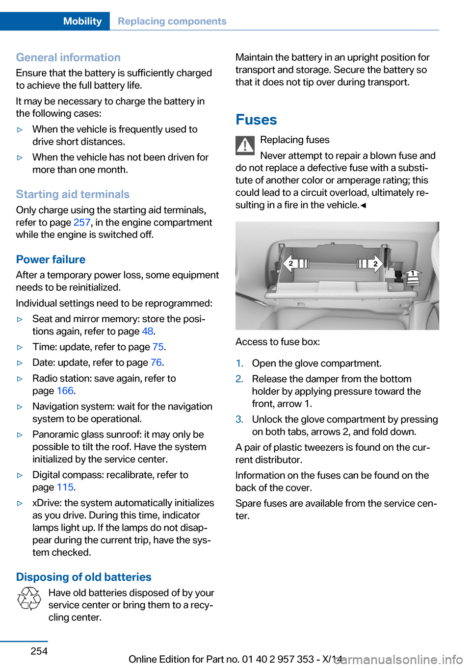
Access to fuse box:
1.Open the glove compartment.2.Release the damper from the bottom
holder by applying pressure toward the
front, arrow 1.3.Unlock the glove compartment by pressing
on both tabs, arrows 2, and fold down.
A pair of plastic tweezers is found on the curŌĆÉ
rent distributor.
Information on the fuses can be found on the
back of the cover.
Spare fuses are available from the service cenŌĆÉ
ter.
Seite 254MobilityReplacing components254
Online Edition for Part no. 01 40 2 957 353 - X/14