tow BMW X1 2016 F48 Owner's Guide
[x] Cancel search | Manufacturer: BMW, Model Year: 2016, Model line: X1, Model: BMW X1 2016 F48Pages: 242, PDF Size: 7.12 MB
Page 170 of 242
Drive through calm water only and only if it is
not deeper than 9.8 inches/25 cm and at this
height, no faster than walking speed, up to
3 mph/5 km/h.
Braking safely Your vehicle is equipped with ABS as a stand‐
ard feature.
Applying the brakes fully is the most effective
way of braking in situations needed.
Steering is still responsive. You can still avoid
any obstacles with a minimum of steering ef‐
fort.
Pulsation of the brake pedal and sounds from
the hydraulic circuits indicate that ABS is in its
active mode.
In certain braking situations, the perforated
brake discs can cause functional problems.
However, this has no effect on the perform‐
ance and operational reliability of the brake.
Objects in the movement area around
pedals and floor area
WARNING
Objects in the driver's floor area can limit
the pedal distance or block a depressed pedal.
There is risk of an accident. Stow objects in
the vehicle such that they are secured and
cannot enter into the driver's floor area. Use
floor mats that are suitable for the vehicle and
can be safely attached to the floor. Do not use
loose floor mats and do not layer several floor
mats. Make sure that there is sufficient clear‐
ance for the pedals. Ensure that the floor mats
are securely fastened again after they were re‐
moved, e.g. for cleaning.◀
Driving in wet conditions
When roads are wet, salted, or in heavy rain,
press brake pedal ever so gently every few
miles.
Ensure that this action does not endanger
other traffic.The heat generated in this process helps dry
the brake discs and pads.
In this way braking efficiency will be available
when you need it.
Hills WARNING
Light but consistent brake pressure can
lead to high temperatures, brakes wearing out
and possibly even brake failure. There is risk of
an accident. Avoid placing excessive stress on
the brake system.◀
WARNING
In idle or with the engine switched off,
safety-relevant functions are restricted or not
available anymore, e.g. braking effect of the
engine or braking force and steering support.
There is risk of an accident. Do not drive in idle or with the engine switched off.◀
Drive long or steep downhill gradients in the
gear that requires least braking efforts. Other‐
wise the brakes may overheat and reduce
brake efficiency.
You can increase the engine's braking effect
by shifting down, going all the way to first gear,
if needed.
Brake disc corrosion
Corrosion on the brake discs and contamina‐
tion on the brake pads are furthered by the fol‐
lowing circumstances:▷Low mileage.▷Extended periods when the vehicle is not
used at all.▷Infrequent use of the brakes.
Corrosion will built up when the maximum
pressure applied to the brake pads during
braking is not reached - thus discs don't get
cleaned.
Corrosion buildup on the brake discs will cause
a pulsating effect on the brakes in their re‐
sponse - generally that cannot be corrected.
Seite 170Driving tipsThings to remember when driving170
Online Edition for Part no. 01 40 2 964 303 - VI/15
Page 173 of 242
Load
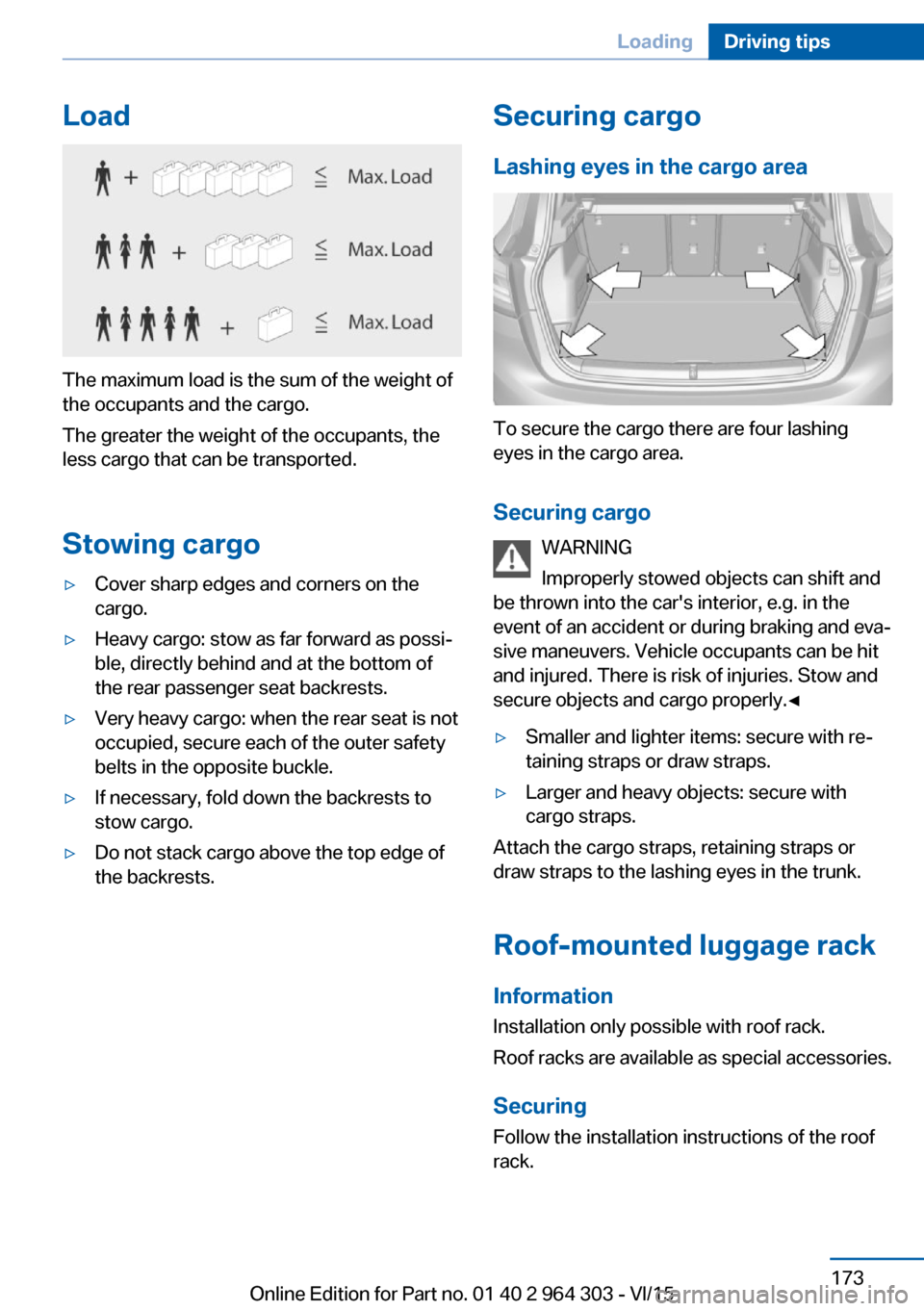
The maximum load is the sum of the weight of
the occupants and the cargo.
The greater the weight of the occupants, the
less cargo that can be transported.
Stowing cargo
▷Cover sharp edges and corners on the
cargo.▷Heavy cargo: stow as far forward as possi‐
ble, directly behind and at the bottom of
the rear passenger seat backrests.▷Very heavy cargo: when the rear seat is not
occupied, secure each of the outer safety
belts in the opposite buckle.▷If necessary, fold down the backrests to
stow cargo.▷Do not stack cargo above the top edge of
the backrests.Securing cargo
Lashing eyes in the cargo area
To secure the cargo there are four lashing
eyes in the cargo area.
Securing cargo WARNING
Improperly stowed objects can shift and
be thrown into the car's interior, e.g. in the
event of an accident or during braking and eva‐
sive maneuvers. Vehicle occupants can be hit
and injured. There is risk of injuries. Stow and
secure objects and cargo properly.◀
▷Smaller and lighter items: secure with re‐
taining straps or draw straps.▷Larger and heavy objects: secure with
cargo straps.
Attach the cargo straps, retaining straps or
draw straps to the lashing eyes in the trunk.
Roof-mounted luggage rack Information
Installation only possible with roof rack.
Roof racks are available as special accessories.
Securing
Follow the installation instructions of the roof
rack.
Seite 173LoadingDriving tips173
Online Edition for Part no. 01 40 2 964 303 - VI/15
Page 190 of 242
Tire treadSummer tires
Do not drive with a tire tread depth of less than
0.12 in/3 mm.
There is an increased danger of hydroplaning if
the tire tread depth is less than 0.12 in/3 mm.
Winter tires
Do not drive with a tire tread depth of less than
0.16 in/4 mm.
Below a tread depth of 0.16 in/4 mm, tires are
less suitable for winter operation.
Minimum tread depth
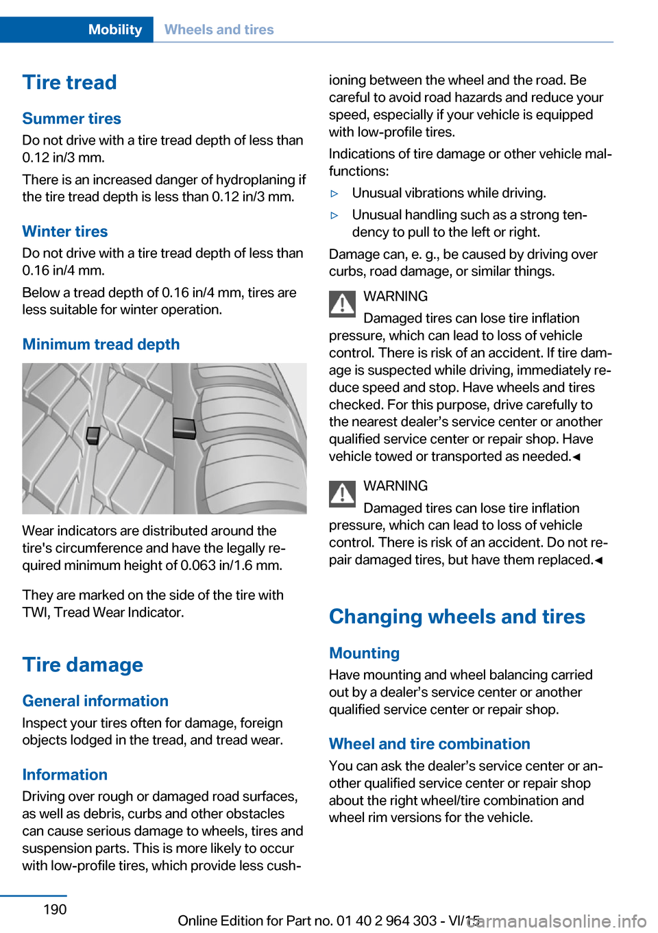
Wear indicators are distributed around the
tire's circumference and have the legally re‐
quired minimum height of 0.063 in/1.6 mm.
They are marked on the side of the tire with
TWI, Tread Wear Indicator.
Tire damage
General information
Inspect your tires often for damage, foreign
objects lodged in the tread, and tread wear.
Information Driving over rough or damaged road surfaces,
as well as debris, curbs and other obstacles
can cause serious damage to wheels, tires and
suspension parts. This is more likely to occur
with low-profile tires, which provide less cush‐
ioning between the wheel and the road. Be
careful to avoid road hazards and reduce your
speed, especially if your vehicle is equipped
with low-profile tires.
Indications of tire damage or other vehicle mal‐
functions:▷Unusual vibrations while driving.▷Unusual handling such as a strong ten‐
dency to pull to the left or right.
Damage can, e. g., be caused by driving over
curbs, road damage, or similar things.
WARNING
Damaged tires can lose tire inflation
pressure, which can lead to loss of vehicle
control. There is risk of an accident. If tire dam‐
age is suspected while driving, immediately re‐
duce speed and stop. Have wheels and tires
checked. For this purpose, drive carefully to
the nearest dealer’s service center or another
qualified service center or repair shop. Have
vehicle towed or transported as needed.◀
WARNING
Damaged tires can lose tire inflation
pressure, which can lead to loss of vehicle
control. There is risk of an accident. Do not re‐
pair damaged tires, but have them replaced.◀
Changing wheels and tires
Mounting Have mounting and wheel balancing carriedout by a dealer’s service center or another
qualified service center or repair shop.
Wheel and tire combination
You can ask the dealer’s service center or an‐
other qualified service center or repair shop
about the right wheel/tire combination and
wheel rim versions for the vehicle.
Seite 190MobilityWheels and tires190
Online Edition for Part no. 01 40 2 964 303 - VI/15
Page 193 of 242
StorageThe Mobility System is located under the
cargo floor panel.
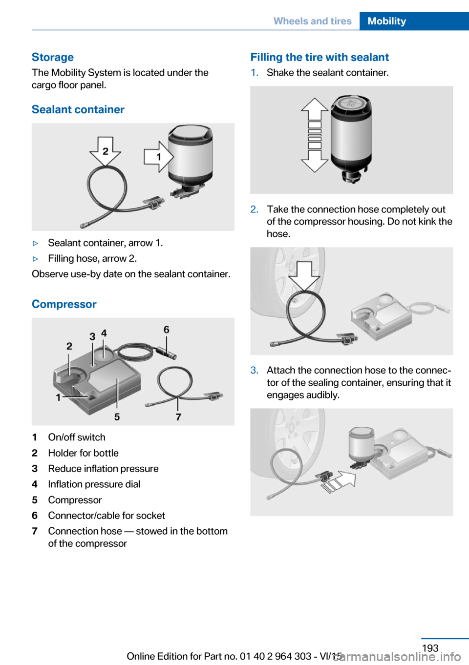
Sealant container▷Sealant container, arrow 1.▷Filling hose, arrow 2.
Observe use-by date on the sealant container.
Compressor
1On/off switch2Holder for bottle3Reduce inflation pressure4Inflation pressure dial5Compressor6Connector/cable for socket7Connection hose — stowed in the bottom
of the compressorFilling the tire with sealant1.Shake the sealant container.2.Take the connection hose completely out
of the compressor housing. Do not kink the
hose.3.Attach the connection hose to the connec‐
tor of the sealing container, ensuring that it
engages audibly.Seite 193Wheels and tiresMobility193
Online Edition for Part no. 01 40 2 964 303 - VI/15
Page 194 of 242
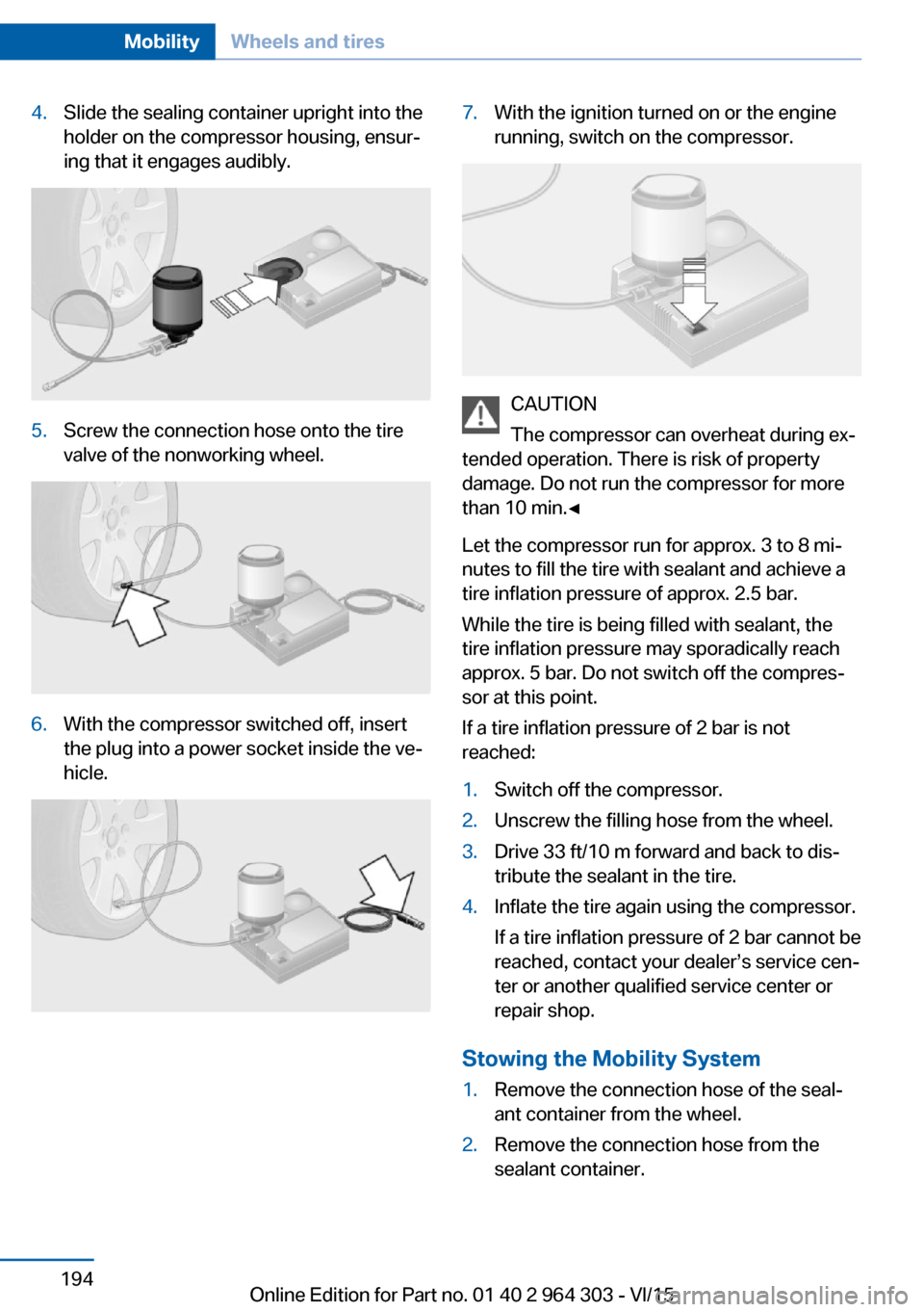
4.Slide the sealing container upright into the
holder on the compressor housing, ensur‐
ing that it engages audibly.5.Screw the connection hose onto the tire
valve of the nonworking wheel.6.With the compressor switched off, insert
the plug into a power socket inside the ve‐
hicle.7.With the ignition turned on or the engine
running, switch on the compressor.
CAUTION
The compressor can overheat during ex‐
tended operation. There is risk of property
damage. Do not run the compressor for more
than 10 min.◀
Let the compressor run for approx. 3 to 8 mi‐
nutes to fill the tire with sealant and achieve a
tire inflation pressure of approx. 2.5 bar.
While the tire is being filled with sealant, the
tire inflation pressure may sporadically reach
approx. 5 bar. Do not switch off the compres‐
sor at this point.
If a tire inflation pressure of 2 bar is not
reached:
1.Switch off the compressor.2.Unscrew the filling hose from the wheel.3.Drive 33 ft/10 m forward and back to dis‐
tribute the sealant in the tire.4.Inflate the tire again using the compressor.
If a tire inflation pressure of 2 bar cannot be
reached, contact your dealer’s service cen‐
ter or another qualified service center or
repair shop.
Stowing the Mobility System
1.Remove the connection hose of the seal‐
ant container from the wheel.2.Remove the connection hose from the
sealant container.Seite 194MobilityWheels and tires194
Online Edition for Part no. 01 40 2 964 303 - VI/15
Page 195 of 242
3.Wrap the empty sealant container and con‐
nection hose in suitable material to avoid
dirtying the trunk.4.Stow the Mobility System back in the vehi‐
cle.
Distributing the sealant
Immediately drive approx. 5 miles/10 km to en‐
sure that the sealant is evenly distributed in the
tire.
Do not exceed a speed of 50 mph/80 km/h.
If possible, do not drive at speeds less than
12 mph/20 km/h.
To correct the tire inflation pressure
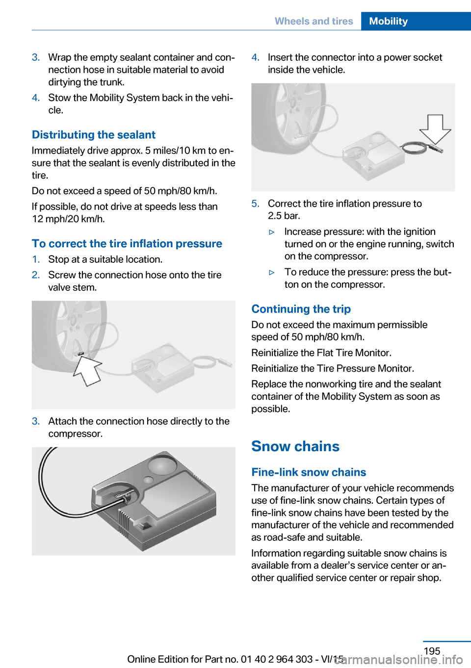
1.Stop at a suitable location.2.Screw the connection hose onto the tire
valve stem.3.Attach the connection hose directly to the
compressor.4.Insert the connector into a power socket
inside the vehicle.5.Correct the tire inflation pressure to
2.5 bar.▷Increase pressure: with the ignition
turned on or the engine running, switch
on the compressor.▷To reduce the pressure: press the but‐
ton on the compressor.
Continuing the trip
Do not exceed the maximum permissible
speed of 50 mph/80 km/h.
Reinitialize the Flat Tire Monitor.
Reinitialize the Tire Pressure Monitor.
Replace the nonworking tire and the sealant
container of the Mobility System as soon as
possible.
Snow chains
Fine-link snow chains
The manufacturer of your vehicle recommends
use of fine-link snow chains. Certain types of
fine-link snow chains have been tested by the
manufacturer of the vehicle and recommended
as road-safe and suitable.
Information regarding suitable snow chains is
available from a dealer’s service center or an‐
other qualified service center or repair shop.
Seite 195Wheels and tiresMobility195
Online Edition for Part no. 01 40 2 964 303 - VI/15
Page 210 of 242
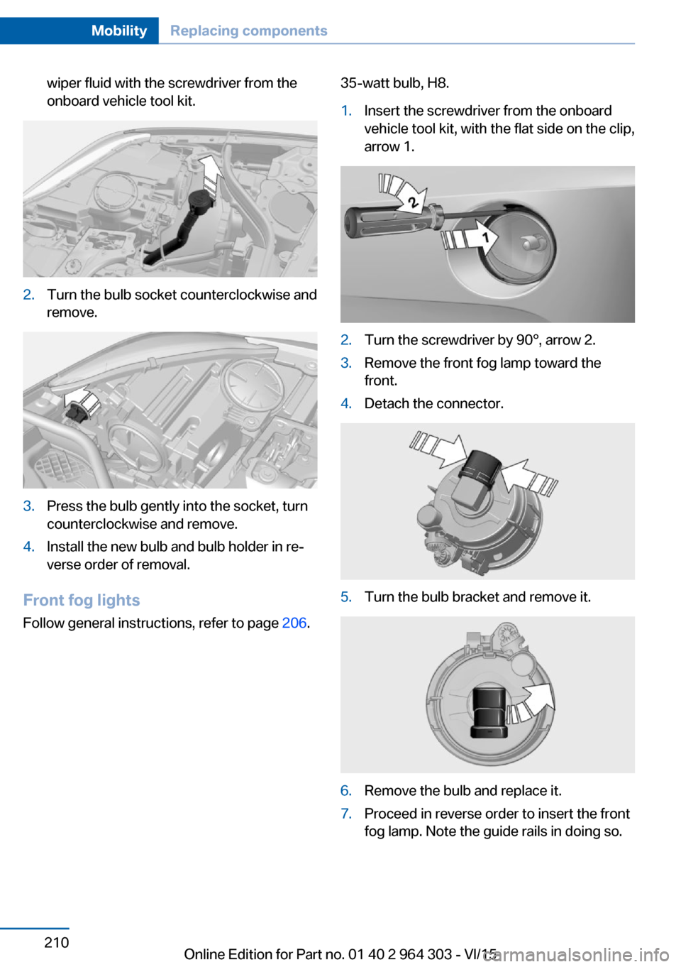
wiper fluid with the screwdriver from the
onboard vehicle tool kit.2.Turn the bulb socket counterclockwise and
remove.3.Press the bulb gently into the socket, turn
counterclockwise and remove.4.Install the new bulb and bulb holder in re‐
verse order of removal.
Front fog lights
Follow general instructions, refer to page 206.
35-watt bulb, H8.1.Insert the screwdriver from the onboard
vehicle tool kit, with the flat side on the clip,
arrow 1.2.Turn the screwdriver by 90°, arrow 2.3.Remove the front fog lamp toward the
front.4.Detach the connector.5.Turn the bulb bracket and remove it.6.Remove the bulb and replace it.7.Proceed in reverse order to insert the front
fog lamp. Note the guide rails in doing so.Seite 210MobilityReplacing components210
Online Edition for Part no. 01 40 2 964 303 - VI/15
Page 211 of 242
Turn signal in exterior mirrorThe turn signals in the exterior mirrors feature
LED technology. Contact a dealer’s service
center or another qualified service center or re‐
pair shop in the event of a malfunction.
Tail lights, bulb replacement
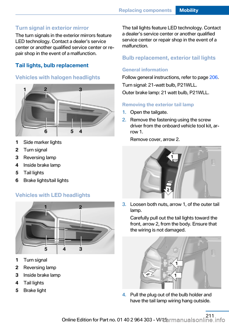
Vehicles with halogen headlights1Side marker lights2Turn signal3Reversing lamp4Inside brake lamp5Tail lights6Brake lights/tail lights
Vehicles with LED headlights
1Turn signal2Reversing lamp3Inside brake lamp4Tail lights5Brake lightThe tail lights feature LED technology. Contact
a dealer’s service center or another qualified
service center or repair shop in the event of a
malfunction.
Bulb replacement, exterior tail lights
General information
Follow general instructions, refer to page 206.
Turn signal: 21-watt bulb, P21WLL.
Outer brake lamp: 21 watt bulb, P21WLL.
Removing the exterior tail lamp1.Open the tailgate.2.Remove the fastening using the screw
driver from the onboard vehicle tool kit, ar‐
row 1.
Remove cover, arrow 2.3.Loosen both nuts, arrow 1, of the outer tail
lamp.
Carefully pull out the tail lights toward the
front, arrow 2, from the body. Ensure that
the wiring is not damaged.4.Pull the plug out of the bulb holder and
have the tail lamp wiring hang outside.Seite 211Replacing componentsMobility211
Online Edition for Part no. 01 40 2 964 303 - VI/15
Page 214 of 242
InformationWARNING
The vehicle jack is optimized for lifting
the vehicle and for the jacking points on the
vehicle only. There is risk of injuries. Do not lift
any other vehicle or cargo using the vehicle
jack.◀
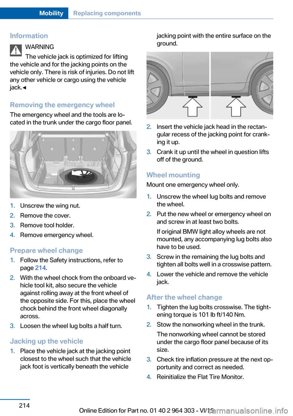
Removing the emergency wheel The emergency wheel and the tools are lo‐
cated in the trunk under the cargo floor panel.1.Unscrew the wing nut.2.Remove the cover.3.Remove tool holder.4.Remove emergency wheel.
Prepare wheel change
1.Follow the Safety instructions, refer to
page 214.2.With the wheel chock from the onboard ve‐
hicle tool kit, also secure the vehicle
against rolling away at the front wheel of
the opposite side. For this, place the wheel
chock behind the front wheel diagonally
across.3.Loosen the wheel lug bolts a half turn.
Jacking up the vehicle
1.Place the vehicle jack at the jacking point
closest to the wheel such that the vehicle
jack foot is vertically beneath the vehiclejacking point with the entire surface on the
ground.2.Insert the vehicle jack head in the rectan‐
gular recess of the jacking point for crank‐
ing it up.3.Crank it up until the wheel in question lifts
off of the ground.
Wheel mounting
Mount one emergency wheel only.
1.Unscrew the wheel lug bolts and remove
the wheel.2.Put the new wheel or emergency wheel on
and screw in at least two bolts.
If original BMW light alloy wheels are not
mounted, any accompanying lug bolts also
have to be used.3.Screw in the remaining the lug bolts and
tighten all bolts well in a crosswise pattern.4.Lower the vehicle and remove the vehicle
jack.
After the wheel change
1.Tighten the lug bolts crosswise. The tight‐
ening torque is 101 lb ft/140 Nm.2.Stow the nonworking wheel in the trunk.
The nonworking wheel cannot be stored
under the cargo floor panel because of its
size.3.Check tire inflation pressure at the next op‐
portunity and correct as needed.4.Reinitialize the Flat Tire Monitor.Seite 214MobilityReplacing components214
Online Edition for Part no. 01 40 2 964 303 - VI/15
Page 219 of 242
Starting aid terminalsWARNING
If the jumper cables are connected in the
incorrect order, sparks formation can occur.
There is risk of injuries. Pay attention to the
correct order during connection.◀
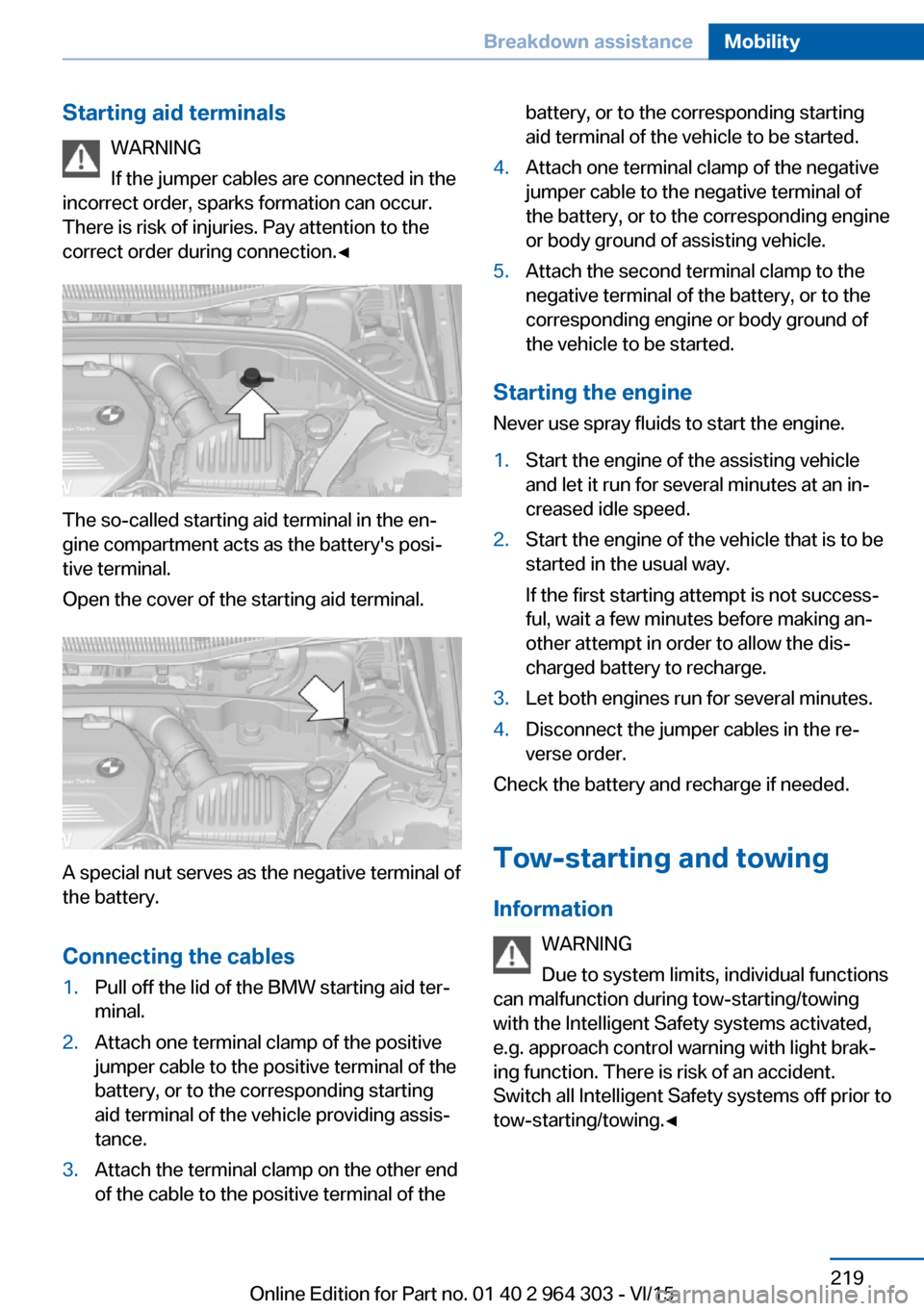
The so-called starting aid terminal in the en‐
gine compartment acts as the battery's posi‐
tive terminal.
Open the cover of the starting aid terminal.
A special nut serves as the negative terminal of
the battery.
Connecting the cables
1.Pull off the lid of the BMW starting aid ter‐
minal.2.Attach one terminal clamp of the positive
jumper cable to the positive terminal of the
battery, or to the corresponding starting
aid terminal of the vehicle providing assis‐
tance.3.Attach the terminal clamp on the other end
of the cable to the positive terminal of thebattery, or to the corresponding starting
aid terminal of the vehicle to be started.4.Attach one terminal clamp of the negative
jumper cable to the negative terminal of
the battery, or to the corresponding engine
or body ground of assisting vehicle.5.Attach the second terminal clamp to the
negative terminal of the battery, or to the
corresponding engine or body ground of
the vehicle to be started.
Starting the engine
Never use spray fluids to start the engine.
1.Start the engine of the assisting vehicle
and let it run for several minutes at an in‐
creased idle speed.2.Start the engine of the vehicle that is to be
started in the usual way.
If the first starting attempt is not success‐
ful, wait a few minutes before making an‐
other attempt in order to allow the dis‐
charged battery to recharge.3.Let both engines run for several minutes.4.Disconnect the jumper cables in the re‐
verse order.
Check the battery and recharge if needed.
Tow-starting and towing Information WARNING
Due to system limits, individual functions
can malfunction during tow-starting/towing
with the Intelligent Safety systems activated,
e.g. approach control warning with light brak‐
ing function. There is risk of an accident.
Switch all Intelligent Safety systems off prior to
tow-starting/towing.◀
Seite 219Breakdown assistanceMobility219
Online Edition for Part no. 01 40 2 964 303 - VI/15