light BMW X1 SDRIVE28I 2014 Workshop Manual
[x] Cancel search | Manufacturer: BMW, Model Year: 2014, Model line: X1 SDRIVE28I, Model: BMW X1 SDRIVE28I 2014Pages: 295, PDF Size: 7.06 MB
Page 112 of 295
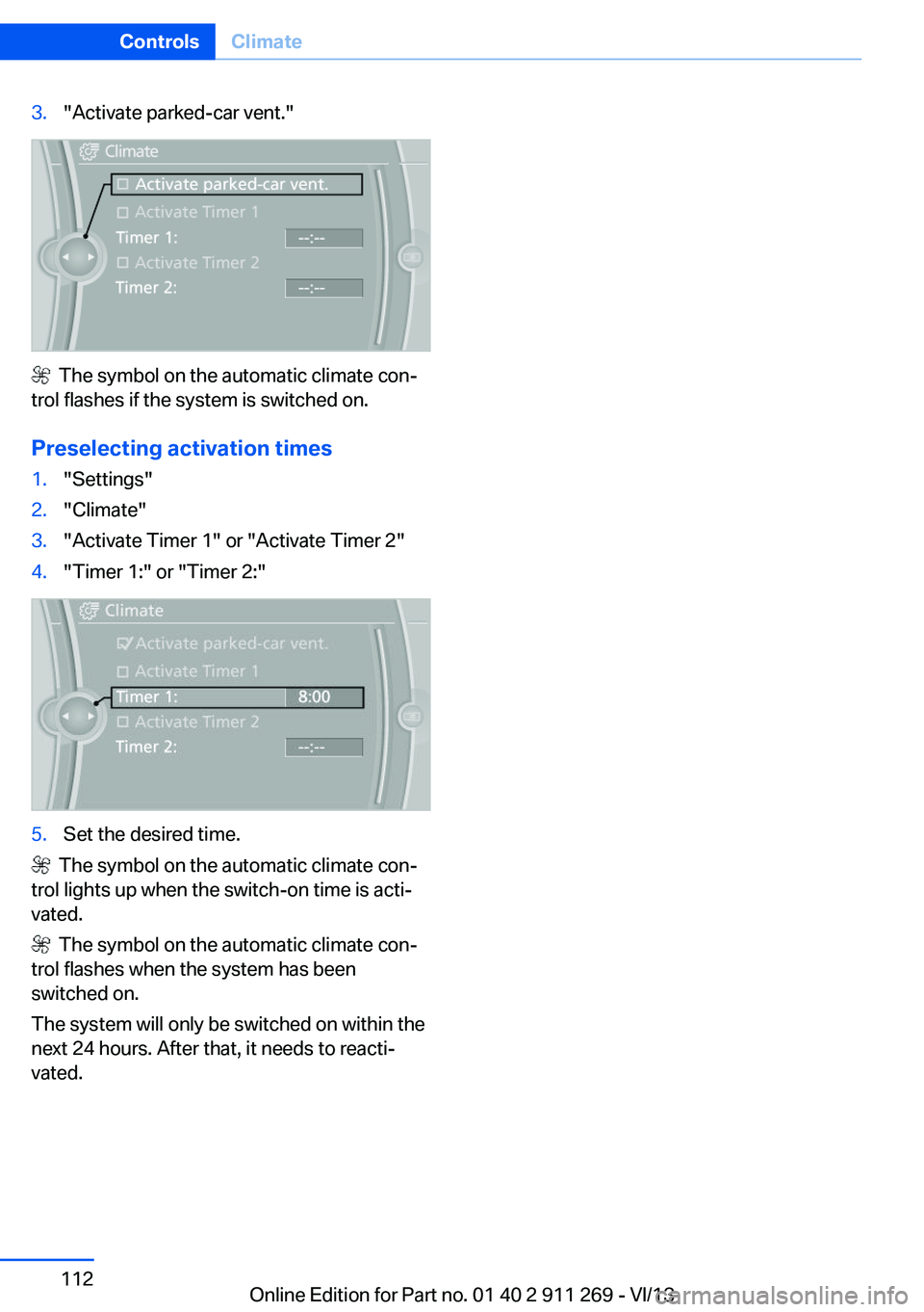
3."Activate parked-car vent."
The symbol on the automatic climate con‐
trol flashes if the system is switched on.
Preselecting activation times
1."Settings"2."Climate"3."Activate Timer 1" or "Activate Timer 2"4."Timer 1:" or "Timer 2:"5.Set the desired time.
The symbol on the automatic climate con‐
trol lights up when the switch-on time is acti‐
vated.
The symbol on the automatic climate con‐
trol flashes when the system has been
switched on.
The system will only be switched on within the
next 24 hours. After that, it needs to reacti‐
vated.
Seite 112ControlsClimate112
Online Edition for Part no. 01 40 2 911 269 - VI/13
Page 113 of 295

Interior equipmentVehicle equipmentThis chapter describes all series equipment as
well as country-specific and special equipment
offered for this model series.Therefore, it also
describes equipment that may not be found in
your vehicle, for instance due to the selected
special equipment or the country version. This
also applies to safety-related functions and
systems.
Universal Garage Door
Opener
The concept The Universal Garage Door Opener can be
used to operate up to 3 functions in remote-
controlled systems, such as garage door drives or lighting systems. The Universal Garage
Door Opener replaces up to 3 different hand-
held transmitters. To operate it, the buttons on
the interior rearview mirror must be program‐
med for the desired functions. The hand-held
transmitter for the system is needed for the
programming procedure.
During programming
During programming and before activat‐
ing a device using the Universal Garage Door
Opener, ensure that there are no people, ani‐
mals, or objects in the range of movement of
the remote-controlled device; otherwise, there
is a risk of injury or damage.
Also follow the safety instructions of the hand-
held transmitter.◀
Before selling the vehicle, delete the stored
functions for security reasons.
Compatibility If this symbol is printed on the packag‐
ing or in the operating instructions ofthe system being operated, the system is gen‐
erally compatible with the Universal Garage
Door Opener.
If you have any questions, please contact:▷Your service center.▷www.homelink.com on the Internet.
HomeLink is a registered trademark of John‐
son Controls, Inc.
Controls on the interior rearview
mirror
1LED2Buttons3Hand-held transmitter, required for pro‐
gramming.
Programming
General information
1.Switch on the ignition.2.Initial setup:
Press the right and left buttons on the inte‐
rior rearview mirror simultaneously for ap‐
prox. 20 seconds until the LED on the inte‐
rior rearview mirror begins to flash. All
programmed settings of the buttons on the
interior rearview mirror are deleted.3.Hold the hand-held transmitter of the sys‐
tem to be operated a distance of approx. 1
to 3 in/2.5 to 8 cm away from the buttonsSeite 113Interior equipmentControls113
Online Edition for Part no. 01 40 2 911 269 - VI/13
Page 114 of 295

on the interior rearview mirror. The re‐
quired distance depends on the particular
hand-held transmitter.4.Press the button of the desired function on
the hand-held transmitter and the button
being programmed on the interior rearview
mirror simultaneously and hold. The LED
on the interior rearview mirror flashes
slowly at first.5.When the LED flashes more rapidly, re‐
lease both buttons. Rapid flashing indi‐
cates that the button on the interior rear‐
view mirror has been programmed.
If the LED does not flash faster after
60 seconds, change the distance between
the interior rearview mirror and the hand-
held transmitter and repeat the step. Multi‐
ple trials at different distances may be nec‐
essary. Wait at least 15 seconds between
trials.6.To program additional functions on other
buttons, repeat steps 3 to 5.
The systems can be operated with the buttons
on the interior rearview mirror.
Special characteristics of alternating-
code radio systems
If the system cannot be operated after re‐
peated programming, check whether the sys‐
tem to be operated uses an alternating-code
system.
Read the operating instructions of the system
or press and hold the programmed button on
the interior rearview mirror. If the LED on the
interior rearview mirror flashes rapidly at first
and then lights up continuously for 2 seconds,
the system is equipped with an alternating-
code system. This flashing LED pattern re‐
peats itself for approx. 20 seconds.
In systems with an alternating-code system,
the Universal Garage Door Opener and the
system must be additionally synchronized.
Please obtain additional information on syn‐
chronization in the operating instructions of
the system being set up.
The systems will be easier to synchronize with
the aid of a second person.
Synchronization:1.Park the vehicle within range of the re‐
mote-controlled system.2.Program the corresponding button on the
interior rearview mirror as described.3.Identify and press the synchronization but‐
ton on the system being set up. You have
approx. 30 seconds for the next step.4.Press and hold the button on the interior
rearview mirror for approx. 3 seconds and
then release it. Repeat this step up to three
times if necessary to complete the syn‐
chronization procedure. When synchroni‐
zation is completed, the programmed func‐
tion is executed.
Reprogramming individual buttons
1.Switch on the ignition.2.Hold the hand-held transmitter at a dis‐
tance of approx. 1 to 3 in/2.5 to 8 cm from
the memory buttons.
The required distance depends on the par‐
ticular hand-held transmitter.3.Press the memory button of the Universal
Garage Door Opener.4.If the LED flashes slowly after approx.
20 seconds, press the transmit button on
the hand-held transmitter.5.Release both buttons when the LED
flashes rapidly.
If the LED does not flash rapidly after ap‐
prox. 60 seconds, change the distance and
repeat the step.
Canada: if the LED does not flash rapidly
after approx. 60 seconds, change the dis‐
tance and repeat the step. If programmingSeite 114ControlsInterior equipment114
Online Edition for Part no. 01 40 2 911 269 - VI/13
Page 115 of 295

was aborted by the hand-held transmitter,
hold down the memory button and press
and release the button on the hand-held
transmitter several times for 2 seconds.
Controls
Prior to operation
Before operating a unit with the Universal
Garage Door Opener, ensure that there are no
people, animals, or objects in the range of
movement of the system; otherwise, there is a
risk of injury or damage.
Also follow the safety instructions of the hand-
held transmitter.◀
The system, such as the garage door, can be
operated using the button on the interior rear‐
view mirror with the engine running or the igni‐
tion switched on. When you are within the re‐
ception range of the system, press and hold
the button until the function is initiated. The
LED on the interior rearview mirror lights up
continuously while the radio signal is being
transmitted.
Deleting stored functions Press the right and left buttons on the interior
rearview mirror simultaneously for approx.
20 seconds until the LED flashes rapidly. All
stored functions are deleted. The functions
cannot be deleted individually.
Digital compass1Adjustment button2Display
The display shows you the main or secondary
compass direction in which you are driving.
Operating concept
Various functions can be called up by pressing
the adjustment button with a pointed object
such as a pen. The following adjustment op‐
tions are displayed one after the other, de‐
pending on how long the adjustment button is
pressed:
▷Press briefly: switch the display on/off.▷3 to 6 seconds: set the compass zone.▷6 to 9 seconds: calibrate the compass.▷9 to 12 seconds: set left-hand/right hand
steering.▷12 to 15 seconds: set the language.
Setting compass zones
Set the compass zone corresponding to the
vehicle's geographic location so that the com‐
pass can function correctly; refer to the world
map with compass zones.
Seite 115Interior equipmentControls115
Online Edition for Part no. 01 40 2 911 269 - VI/13
Page 117 of 295

Ashtray/cigarette lighterOpening
Pull cover 2 up.
Emptying
Take out the insert.
Lighter With the engine running or the ignition
switched on, press in the cigarette lighter 1.
The lighter can be removed as soon as it pops
back out.
Danger of burns
Only hold the hot lighter by its head; oth‐
erwise, there is the danger of getting burned.
Switch off the ignition and take the remote
control with you when leaving the vehicle so
that children cannot use the lighter and burn
themselves.◀
Replace the cover after use
Replace the lighter or socket cover after
use; otherwise, objects that fall into the lighter
socket or power socket could cause a short
circuit.◀
Connecting electrical
devices
Note Do not connect the charger to the socket
Do not connect the battery charger to
the socket installed in the vehicle at the factory
as this could damage the battery.◀
Sockets The lighter socket can be used as a socket for
electrical equipment while the engine is run‐
ning or when the ignition is switched on. The
total load of all sockets must not exceed
140 watts at 12 volt.
Avoid damaging the sockets by attempting to
insert plugs of unsuitable shape or size.
Front center console
Remove the cover or cigarette lighter.
Rear center console
Remove the cover or cigarette lighter.
Seite 117Interior equipmentControls117
Online Edition for Part no. 01 40 2 911 269 - VI/13
Page 118 of 295

In storage compartment under center
armrest
To access the socket: remove the cover.
In cargo area
Fold open the cover.
Cargo area Cargo covers Do not place objects on the covers
Do not place objects on the cover; if you
do so, they may pose a danger to vehicle occu‐
pants during braking or evasive maneuvers or
damage the cover.◀
To load bulky luggage, the covers can be re‐
moved.
Rear cover
1.Detach the securing straps from the tail‐
gate.2.Lift the cover slightly, arrow 1, and pull it
back and out of the brackets, arrows 2.Front cover1.Push the cover up and out of the brackets
on both sides at the rear, arrow 1.2.Pull the cover back, up and out of the lat‐
eral brackets on both sides, arrow 2.
Enlarging the cargo area
General information
The cargo area can be enlarged by folding
down the rear seat backrests.
The rear seat backrest is divided at a ratio of
40-20-40.
The backrests can be adjusted to 10 different
positions between the comfort and transport
positions and they can be folded down.
In the comfort position, the backrests are tilted
back to the greatest possible angle and in the
transport position they are nearly vertical.
Before mounting a child restraint fixing system,
note the instructions, refer to page 52.
Danger of pinching
Before folding down the rear seat back‐
rests, ensure that path of movement of the
backrests is clear. Especially when the middle
section is folded down, ensure that no one is
located in or reaches into the path of move‐
ment of the rear seat backrests. Otherwise, in‐
juries or damage may result.◀
Seite 118ControlsInterior equipment118
Online Edition for Part no. 01 40 2 911 269 - VI/13
Page 121 of 295

RemovingTo remove and stow the partition net, proceed
in reverse order.
To fold up, press both release buttons, arrows.
Cargo floor panel
Compartment in floor Note the maximum permissible load
Do not exceed a maximum load of
55 lbs/25 kg in the storage compartment be‐
neath the cargo floor panel; otherwise, damage
may result.◀
To access the tool kit, for example, lift the stor‐
age compartment at the rear.
To lift, reach into the recess on the rear edge
of the storage compartment.
The storage compartment can be removed if
necessary.
Raising the cargo floor panel
Reach under the cargo floor panel on the left,
right and at the rear. Fold the panel up and for‐
ward, pressing it into the gap between the
cargo area floor and the rear seat backrest.
Do not apply pressure to the cargo floor
panel when it is upright.
Do not apply pressure to the cargo floor panel
when it is upright, do not press up or down on
it, and do not adjust the rear seat backrests;
otherwise, damage may result.◀
Before closing the tailgate, fold down the
cargo floor panel. To do this, pull the cargo
floor panel toward the rear, raising it up and out
of the gap.
The cargo floor panel can be removed if nec‐
essary.
Lashing eyes
To secure pieces of luggage with nets or draw
straps, lashing eyes are available in the cargo
area, refer to page 135.
Multi-function hooks
Hooks designed for hanging shopping bags
and totes, for example, are located on the left
and right sides of the cargo cover support, ar‐
row.
Do not hang heavy items from the hooks
Only hang light bags or suitable objects
from the holders. Otherwise, there is a danger
of objects flying about during braking and eva‐
sive maneuvers.
Only transport heavy luggage in the trunk if it
has been appropriately secured.◀
Seite 121Interior equipmentControls121
Online Edition for Part no. 01 40 2 911 269 - VI/13
Page 123 of 295

Storage compartmentsVehicle equipmentThis chapter describes all series equipment as
well as country-specific and special equipment
offered for this model series.Therefore, it also
describes equipment that may not be found in
your vehicle, for instance due to the selected
special equipment or the country version. This
also applies to safety-related functions and
systems.
Notes No loose objects in the passenger com‐
partment
Do not stow any objects in the passenger
compartment without securing them; other‐
wise, they may present a danger to occupants
for instance during braking and avoidance ma‐ neuvers.◀
No non-slip mats on the dashboard
Do not use non-slip materials, such as
non-slip mats, on the dashboard, or it could be
damaged by the substances in the materials.◀
Glove compartmentOpening
Pull the handle.
The light in the glove compartment switches
on.
Close the glove compartment again im‐
mediately
Close the glove compartment immediately af‐
ter use while driving; otherwise, injury may oc‐
cur during accidents.◀
ClosingFold up the cover.
USB interface for data transfer
Port for importing and exporting data, such as
music collections, refer to page 179, on USB
devices.
Observe the following when connecting:
▷Do not use force when plugging the con‐
nector into the USB interface.▷Do not connect devices such as fans or
lamps to the USB interface.▷Do not connect a USB hard drive.▷Do not use the USB interface to recharge
external devices.Seite 123Storage compartmentsControls123
Online Edition for Part no. 01 40 2 911 269 - VI/13
Page 125 of 295

Storage compartment package
For your comfort:
Interior▷Insertable cupholder, refer to page 125.▷Front center armrest, refer to page 124.▷Nets on the backrests of the front seats.▷Retaining straps in the front door compart‐
ments.▷Rear center armrest with integrated cu‐
pholders.
Cargo area
▷Retaining strap on the left side panel for
securing small items.▷Retaining straps on the cargo area floor.▷Insertable partition elements for the stor‐
age compartment under the cargo floor
panel, used to variably subdivide the stor‐
age compartment.
With partition net: arrange the partition ele‐
ments in such a way that there is enough
space at the rear of the storage compart‐
ment for the partition net.▷Storage net next to the storage compart‐
ment on the right in the cargo area.
Clothes hooks
The clothes hooks are located at the grab han‐
dles in the rear.
Do not obstruct view
When suspending clothing from the
hooks, ensure that it will not obstruct the driv‐
er's vision.◀
No heavy objects
Do not hang heavy objects from the
hooks; otherwise, they may present a danger
to passengers during braking and evasive ma‐
neuvers.◀
Cupholders
Notes Shatter-proof containers and no hot
drinks
Use light and shatter-proof containers and do
not transport hot drinks. Otherwise, there is
the increased danger of injury in an accident.◀
Unsuitable containers
Do not forcefully push unsuitable con‐
tainers into the cupholders. This may result in
damage.◀
Front▷In the front door compartments as a bottle
holder for 1-quart/1 liter bottles, for exam‐
ple.
Insert the bottle into the bottle holder with
the bottom slanted toward the front.▷In the center console.
Insertable cupholder.
The insertable cupholder is located in the
compartment below the center armrest.
Insert the cupholder in the holder on the center
console.
Rear
▷In the front door compartments as a bottle
holder for 25-ounce/0.75 liter bottles, for
example.Seite 125Storage compartmentsControls125
Online Edition for Part no. 01 40 2 911 269 - VI/13
Page 131 of 295

Do not remove the heat shields installed and
never apply undercoating to them. Make sure
that flammable materials, e. g. hay, leaves,
grass, etc. do not come in contact with the hot
exhaust system during driving, while in idle po‐
sition mode, or when parked. Such contact
could lead to a fire, and with it the risk of seri‐
ous personal injury as well as property dam‐
age.
Do not touch hot exhaust pipes; otherwise,
there is the danger of getting burned.◀
Mobile communication devices in the
vehicle
Mobile communication devices in the ve‐
hicle
It is not recommended to use mobile phones,
such as mobile phones without a direct con‐
nection to an external aerial in the vehicle's
passenger compartment. Otherwise, the vehi‐
cle electronics and mobile communication de‐ vices can interfere with each other. In addition,
there is no assurance that the radiation gener‐
ated during transmission will be discharged
from the vehicle interior.◀
Hydroplaning On wet or slushy roads, a wedge of water can
form between the tires and road surface.
This phenomenon is referred to as hydroplan‐
ing. It is characterized by a partial or complete loss of contact between the tires and the road
surface, ultimately undermining your ability to
steer and brake the vehicle.
Hydroplaning
When driving on wet or slushy roads, re‐
duce your speed to prevent hydroplaning.◀
The risk of hydroplaning increases as the tire
tread depth decreases. Minimum tread depth,
refer to page 238.Driving through water
Drive though calm water only if it is not deeper
than 12 inches/30 cm and at this height, no
faster than walking speed, up to
6 mph/10 km/h.
Adhere to water depth and speed limita‐
tions
Do not exceed this water depth and walking speed; otherwise, the vehicle's engine, the
electrical systems and the transmission may
be damaged.◀
Braking safely
Your vehicle is equipped with ABS as a stand‐
ard feature.
Applying the brakes fully is the most effective
way of braking in situations when this is neces‐
sary.
The vehicle maintains steering responsive‐
ness. You can still avoid any obstacles with a
minimum of steering effort.
Pulsation of the brake pedal and sounds from
the hydraulic circuits indicate that ABS is in its
active mode.
Do not let your foot rest on the brake
pedal
Do not drive with your foot resting on the brake
pedal. Even light but consistent pedal pressure
can lead to high temperatures, brake wear and
possibly even brake failure.◀
Objects in the area around the pedals No objects in the area around the pedals
Keep floor mats, carpets, and any other
objects out of the area of motion of the pedals;
otherwise, the function of the pedals could be
impeded while driving
Do not place additional floor mats over existing
mats or other objects.
Only use floor mats that have been approved
for the vehicle and can be properly fixed in
place.Seite 131Things to remember when drivingDriving tips131
Online Edition for Part no. 01 40 2 911 269 - VI/13