children BMW X3 2011 F25 Owner's Manual
[x] Cancel search | Manufacturer: BMW, Model Year: 2011, Model line: X3, Model: BMW X3 2011 F25Pages: 262, PDF Size: 11.2 MB
Page 5 of 262
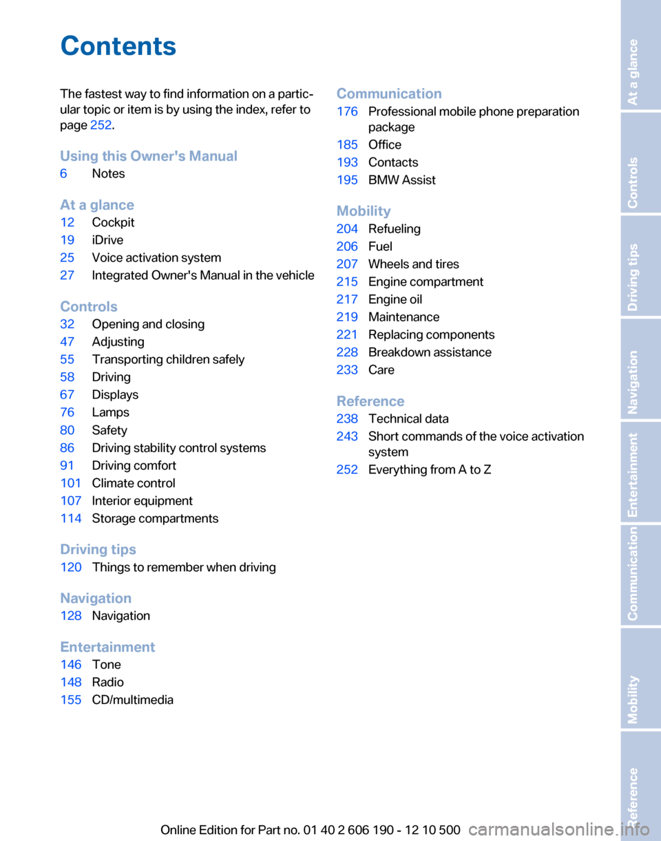
ContentsThe fastest way to find information on a partic‐
ular topic or item is by using the index, refer to
page 252.
Using this Owner's Manual6Notes
At a glance
12Cockpit19iDrive25Voice activation system27Integrated Owner's Manual in the vehicle
Controls
32Opening and closing47Adjusting55Transporting children safely58Driving67Displays76Lamps80Safety86Driving stability control systems91Driving comfort101Climate control107Interior equipment114Storage compartments
Driving tips
120Things to remember when driving
Navigation
128Navigation
Entertainment
146Tone148Radio155CD/multimediaCommunication176Professional mobile phone preparation
package185Office193Contacts195BMW Assist
Mobility
204Refueling206Fuel207Wheels and tires215Engine compartment217Engine oil219Maintenance221Replacing components228Breakdown assistance233Care
Reference
238Technical data243Short commands of the voice activation
system252Everything from A to ZSeite 5
Online Edition for Part no. 01 40 2 606 190 - 12 10 500
ReferenceMobilityCommunicationEntertainmentNavigationDriving tipsControlsAt a glance
Page 43 of 262
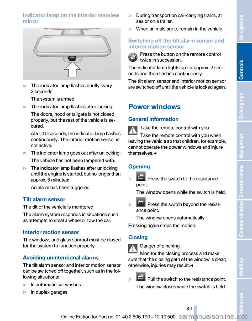
Indicator lamp on the interior rearview
mirror▷The indicator lamp flashes briefly every
2 seconds:
The system is armed.▷The indicator lamp flashes after locking:
The doors, hood or tailgate is not closed
properly, but the rest of the vehicle is se‐
cured.
After 10 seconds, the indicator lamp flashes
continuously. The interior motion sensor is
not active.▷The indicator lamp goes out after unlocking:
The vehicle has not been tampered with.▷The indicator lamp flashes after unlocking
until the engine is started, but no longer than
approx. 5 minutes:
An alarm has been triggered.
Tilt alarm sensor
The tilt of the vehicle is monitored.
The alarm system responds in situations such
as attempts to steal a wheel or tow the car.
Interior motion sensor
The windows and glass sunroof must be closed
for the system to function properly.
Avoiding unintentional alarms
The tilt alarm sensor and interior motion sensor
can be switched off together, such as in the fol‐
lowing situations:
▷In automatic car washes▷In duplex garages.▷During transport on car-carrying trains, at
sea or on a trailer.▷When animals are to remain in the vehicle.
Switching off the tilt alarm sensor and
interior motion sensor
Press the button on the remote control
twice in succession.
The indicator lamp lights up for approx. 2 sec‐
onds and then flashes continuously.
The tilt alarm sensor and interior motion sensor
are switched off until the vehicle is locked again.
Power windows
General information Take the remote control with you
Take the remote control with you when
leaving the vehicle so that children, for example,
cannot operate the power windows and injure
themselves.◀
Opening
▷ Press the switch to the resistance
point.
The window opens while the switch is held.▷ Press the switch beyond the resist‐
ance point.
The window opens automatically.
Pressing again stops the motion.
Closing Danger of pinching
Monitor the closing process and make
sure that the closing path of the window is clear;
otherwise, injuries may result.◀
▷ Pull the switch to the resistance point.
The window closes while the switch is held.
Seite 4343
Online Edition for Part no. 01 40 2 606 190 - 12 10 500
ReferenceMobilityCommunicationEntertainmentNavigationDriving tipsControlsAt a glance
Page 44 of 262
▷ Pull the switch beyond the resistance
point.
The window closes automatically.
Pressing the switch stops the motion.
Convenient operation, refer to page 36, via the
remote control.
Convenient closing, refer to page 41, with Com‐
fort Access*.
Pinch protection
If the closing force exceeds a specific value as a
window closes, the closing action is interrupted.
The window reopens slightly.
Danger of pinching even with pinch pro‐
tection
Even with the pinch protection system, check
that the window's closing path is clear; other‐
wise, the closing action may not stop in certain
situations, e.g., if thin objects are present.◀
Window accessories
Do not install any accessories in the range
of movement of the windows; otherwise, the
pinch protection system will be impaired.◀
Closing without the pinch protection
system
Danger of pinching
Monitor the closing process and make
sure that the closing path of the window is clear;
otherwise, injuries may result.◀
For example, if there is an external danger or if
ice on the windows prevents a window from
closing normally, proceed as follows:
1.Pull the switch past the resistance point and
hold it there.
Pinch protection is limited and the window
reopens slightly if the closing force exceeds
a certain value.2.Pull the switch past the resistance point
again within approx. 4 seconds and hold it
there.The window closes without pinch protec‐
tion.
Safety switch
The safety switch in the driver's door can be
used to prevent children, for example, from
opening and closing the rear windows using the
switches in the rear.
Switching on and off Press the button.
The LED lights up if the safety function
is switched on.
Safety switch for rear operation
Press the safety switch when transporting
children in the rear; otherwise, injury may result
if the windows are closed without supervision. ◀
Initializing after a power failure
After a power failure, it may only be possible to
operate the windows to a limited extent.
Initializing the system Danger of pinching
Monitor the closing process and make
sure that the closing path of the window is clear;
otherwise, injuries may result.◀
Pull the switch past the resistance point
and hold it there until the window is closed.
Roller sunblinds*
Roller sunblinds for the rear side
windows
Pull out the roller sunblind at the loop and hook
it onto the bracket.
Do not open the window while the roller
sunblind is raised.
Do not open the window while the roller sunblind
is raised; otherwise, there is a risk of damage at
high speeds that may result in personal injury. ◀
Seite 4444
Online Edition for Part no. 01 40 2 606 190 - 12 10 500Opening and closing
Page 45 of 262
Panoramic glass sunroof*
General information
The glass sunroof and the sliding visor can be
operated together or separately, using the same
switch.
The glass sunroof is operational when the igni‐
tion is switched on.
Danger of pinching
Monitor the closing process and make
sure that the closing path of the glass sunroof is
clear; otherwise, injuries may result.◀
Take the remote control with you
Take the remote control with you when
leaving the vehicle so that children, for example,
cannot operate the roof and injure themselves. ◀
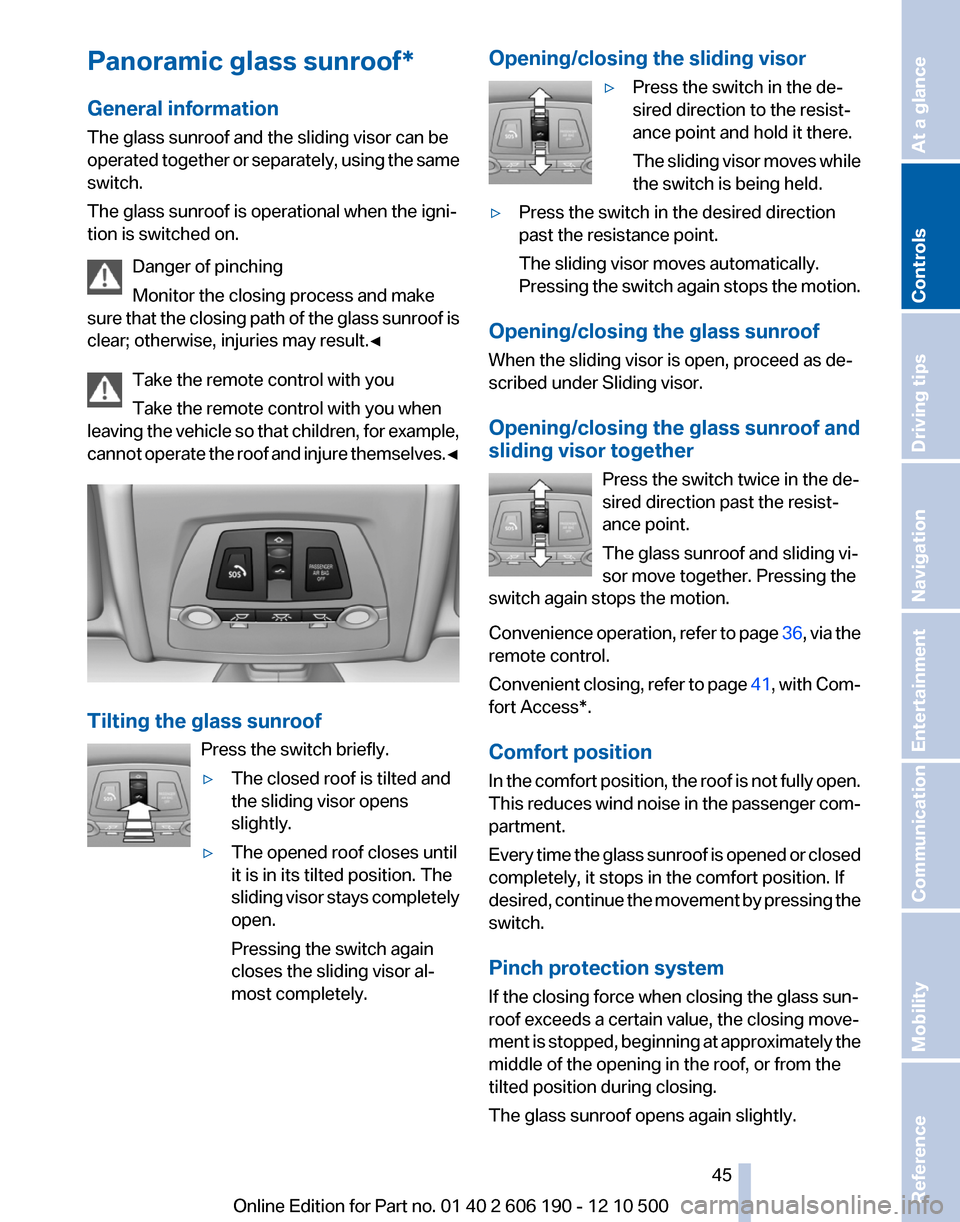
Tilting the glass sunroof
Press the switch briefly.
▷The closed roof is tilted and
the sliding visor opens
slightly.▷The opened roof closes until
it is in its tilted position. The
sliding visor stays completely
open.
Pressing the switch again
closes the sliding visor al‐
most completely.Opening/closing the sliding visor▷Press the switch in the de‐
sired direction to the resist‐
ance point and hold it there.
The sliding visor moves while
the switch is being held.▷Press the switch in the desired direction
past the resistance point.
The sliding visor moves automatically.
Pressing the switch again stops the motion.
Opening/closing the glass sunroof
When the sliding visor is open, proceed as de‐
scribed under Sliding visor.
Opening/closing the glass sunroof and
sliding visor together
Press the switch twice in the de‐
sired direction past the resist‐
ance point.
The glass sunroof and sliding vi‐
sor move together. Pressing the
switch again stops the motion.
Convenience operation, refer to page 36, via the
remote control.
Convenient closing, refer to page 41, with Com‐
fort Access*.
Comfort position
In the comfort position, the roof is not fully open.
This reduces wind noise in the passenger com‐
partment.
Every time the glass sunroof is opened or closed
completely, it stops in the comfort position. If
desired, continue the movement by pressing the
switch.
Pinch protection system
If the closing force when closing the glass sun‐
roof exceeds a certain value, the closing move‐
ment is stopped, beginning at approximately the
middle of the opening in the roof, or from the
tilted position during closing.
The glass sunroof opens again slightly.
Seite 4545
Online Edition for Part no. 01 40 2 606 190 - 12 10 500
ReferenceMobilityCommunicationEntertainmentNavigationDriving tipsControlsAt a glance
Page 50 of 262
Switching off
Press the button longer.
The LEDs go out.
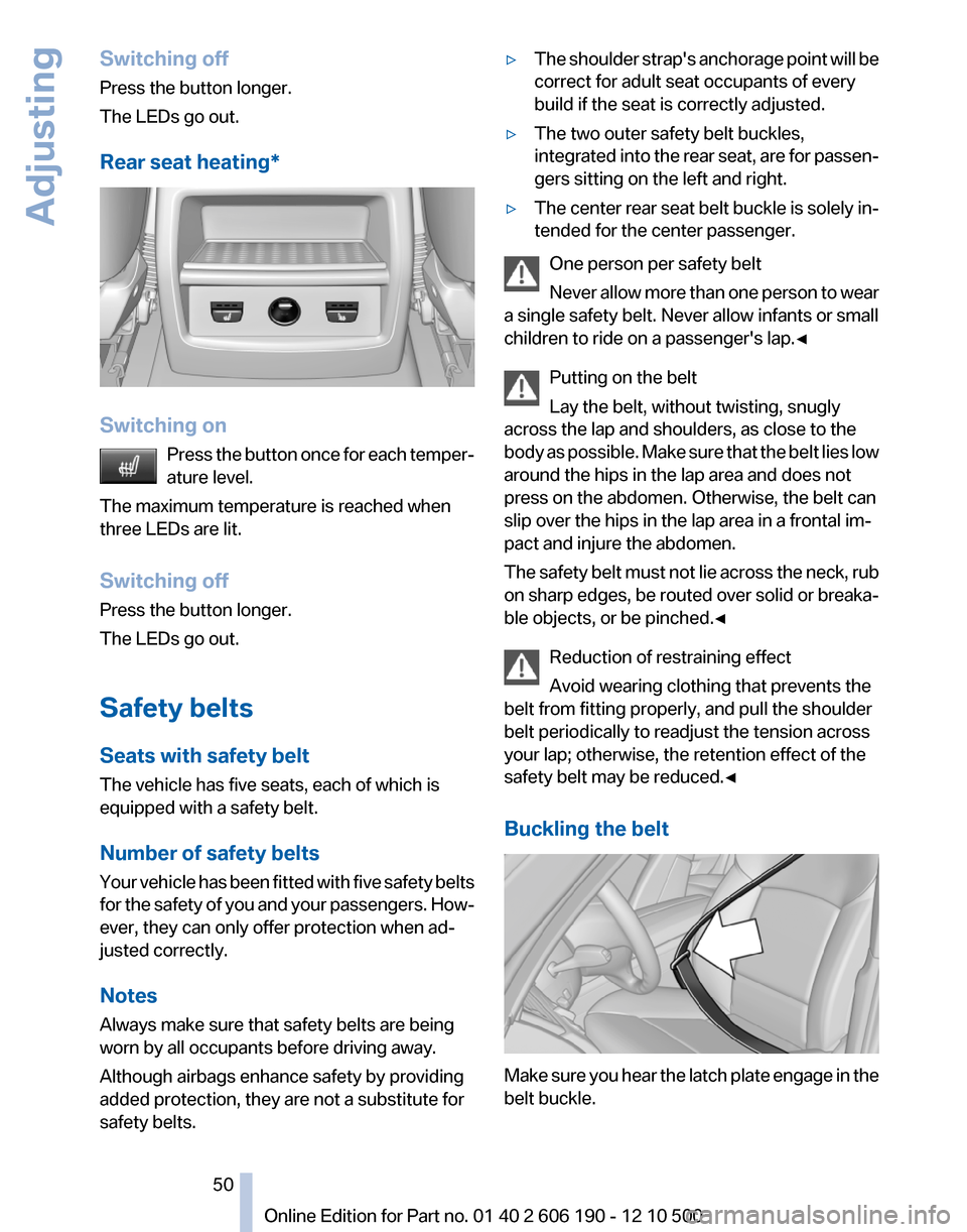
Rear seat heating*
Switching on Press the button once for each temper‐
ature level.
The maximum temperature is reached when
three LEDs are lit.
Switching off
Press the button longer.
The LEDs go out.
Safety belts
Seats with safety belt
The vehicle has five seats, each of which is
equipped with a safety belt.
Number of safety belts
Your vehicle has been fitted with five safety belts
for the safety of you and your passengers. How‐
ever, they can only offer protection when ad‐
justed correctly.
Notes
Always make sure that safety belts are being
worn by all occupants before driving away.
Although airbags enhance safety by providing
added protection, they are not a substitute for
safety belts.
▷The shoulder strap's anchorage point will be
correct for adult seat occupants of every
build if the seat is correctly adjusted.▷The two outer safety belt buckles,
integrated into the rear seat, are for passen‐
gers sitting on the left and right.▷The center rear seat belt buckle is solely in‐
tended for the center passenger.
One person per safety belt
Never allow more than one person to wear
a single safety belt. Never allow infants or small
children to ride on a passenger's lap.◀
Putting on the belt
Lay the belt, without twisting, snugly
across the lap and shoulders, as close to the
body as possible. Make sure that the belt lies low
around the hips in the lap area and does not
press on the abdomen. Otherwise, the belt can
slip over the hips in the lap area in a frontal im‐
pact and injure the abdomen.
The safety belt must not lie across the neck, rub
on sharp edges, be routed over solid or breaka‐
ble objects, or be pinched.◀
Reduction of restraining effect
Avoid wearing clothing that prevents the
belt from fitting properly, and pull the shoulder
belt periodically to readjust the tension across
your lap; otherwise, the retention effect of the
safety belt may be reduced.◀
Buckling the belt
Make sure you hear the latch plate engage in the
belt buckle.
Seite 5050
Online Edition for Part no. 01 40 2 606 190 - 12 10 500Adjusting
Page 55 of 262
Transporting children safelyThe right place for children
Note Children in the vehicle
Do not leave children unattended in the
vehicle; otherwise, they could endanger them‐
selves and other persons, e.g., by opening the
doors.◀
Children should always be in the rear
Accident research shows that the safest place
for children is in the back seat.
Transporting children in the rear
Only transport children younger than
13 years of age or shorter than 5 ft/150 cm in the
rear in child restraint fixing systems provided in
accordance with the age, weight and size of the
child; otherwise, there is an increased risk of in‐
jury in an accident.
Children 13 years of age or older must wear a
safety belt as soon as a suitable child restraint
fixing system can no longer be used, due to their
age, weight and size.◀
Children on the front passenger seat
Should it ever be necessary to use a child re‐
straint fixing system in the front passenger seat,
make sure that the front, knee and side airbags
on the front passenger side are deactivated. Au‐
tomatic deactivation of front passenger airbags,
refer to page 81.
Deactivating the front passenger airbags
If a child restraint fixing system is used in
the front passenger seat, the front passenger
airbags must be deactivated; otherwise, there is
an increased risk of injury to the child when the
airbags are triggered, even with a child restraint
fixing system.◀Installing child restraint fixing
systems
Before mounting
Before mounting child restraint fixing systems,
ensure that the rear seat backrests are locked.
Notes Manufacturer's information for child re‐
straint fixing systems
To select, mount and use child restraint fixing
systems, observe the information provided by
the system manufacturer; otherwise, the pro‐
tective effect can be impaired.◀
On the front passenger seat
After installing a child restraint fixing system in
the front passenger seat, make sure that the
front, knee and side airbags on the front pas‐
senger side are deactivated.
Deactivate the front passenger airbags auto‐
matically, refer to page 81.
Deactivating the front passenger airbags
If a child restraint fixing system is used in
the front passenger seat, the front passenger
airbags must be deactivated; otherwise, there is
an increased risk of injury to the child when the
airbags are triggered, even with a child restraint
fixing system.◀
Seat position and height
Before installing a child restraint fixing system,
move the front passenger seat as far back as
possible and adjust its height to the highest po‐
sition to obtain the best possible position for the
belt and to offer optimal protection in the event
of an accident.
Do not change the seat position and height after
this.Seite 5555
Online Edition for Part no. 01 40 2 606 190 - 12 10 500
ReferenceMobilityCommunicationEntertainmentNavigationDriving tipsControlsAt a glance
Page 56 of 262
Backrest width*
Before installing a child restraint fixing system in
the front passenger seat, open the backrest
width completely. Do not change the backrest
width again and do not call up a memory posi‐
tion.
Backrest width for the child seat
Before installing a child restraint fixing
system in the front passenger seat, the backrest
width must be opened completely. Do not
change the adjustment after this; otherwise, the
stability of the child seat will be reduced.◀
Child seat security
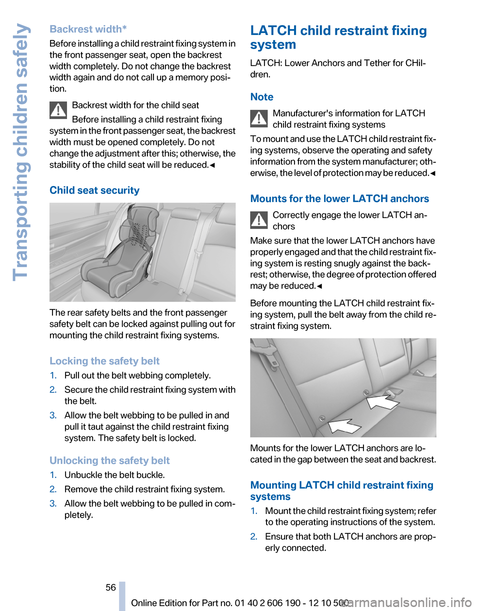
The rear safety belts and the front passenger
safety belt can be locked against pulling out for
mounting the child restraint fixing systems.
Locking the safety belt
1.Pull out the belt webbing completely.2.Secure the child restraint fixing system with
the belt.3.Allow the belt webbing to be pulled in and
pull it taut against the child restraint fixing
system. The safety belt is locked.
Unlocking the safety belt
1.Unbuckle the belt buckle.2.Remove the child restraint fixing system.3.Allow the belt webbing to be pulled in com‐
pletely.LATCH child restraint fixing
system
LATCH: Lower Anchors and Tether for CHil‐
dren.
Note Manufacturer's information for LATCH
child restraint fixing systems
To mount and use the LATCH child restraint fix‐
ing systems, observe the operating and safety
information from the system manufacturer; oth‐
erwise, the level of protection may be reduced. ◀
Mounts for the lower LATCH anchors Correctly engage the lower LATCH an‐
chors
Make sure that the lower LATCH anchors have
properly engaged and that the child restraint fix‐
ing system is resting snugly against the back‐
rest; otherwise, the degree of protection offered
may be reduced.◀
Before mounting the LATCH child restraint fix‐
ing system, pull the belt away from the child re‐
straint fixing system.
Mounts for the lower LATCH anchors are lo‐
cated in the gap between the seat and backrest.
Mounting LATCH child restraint fixing
systems
1.Mount the child restraint fixing system; refer
to the operating instructions of the system.2.Ensure that both LATCH anchors are prop‐
erly connected.Seite 5656
Online Edition for Part no. 01 40 2 606 190 - 12 10 500Transporting children safely
Page 57 of 262
Child restraint fixing system with a
tether strap
Mounting points
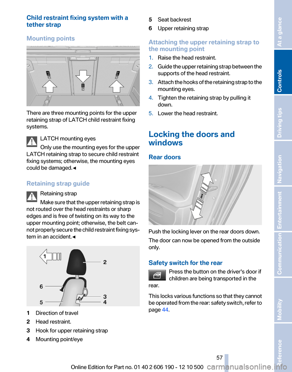
There are three mounting points for the upper
retaining strap of LATCH child restraint fixing
systems.
LATCH mounting eyes
Only use the mounting eyes for the upper
LATCH retaining strap to secure child restraint
fixing systems; otherwise, the mounting eyes
could be damaged.◀
Retaining strap guide Retaining strap
Make sure that the upper retaining strap is
not routed over the head restraints or sharp
edges and is free of twisting on its way to the
upper mounting point; otherwise, the belt can‐
not properly secure the child restraint fixing sys‐
tem in an accident.◀
1Direction of travel2Head restraint.3Hook for upper retaining strap4Mounting point/eye5Seat backrest6Upper retaining strap
Attaching the upper retaining strap to
the mounting point
1.Raise the head restraint.2.Guide the upper retaining strap between the
supports of the head restraint.3.Attach the hooks of the retaining strap to the
mounting eyes.4.Tighten the retaining strap by pulling it
down.5.Lower the head restraint.
Locking the doors and
windows
Rear doors
Push the locking lever on the rear doors down.
The door can now be opened from the outside
only.
Safety switch for the rear Press the button on the driver's door if
children are being transported in the
rear.
This locks various functions so that they cannot
be operated from the rear: safety switch, refer to
page 44.
Seite 5757
Online Edition for Part no. 01 40 2 606 190 - 12 10 500
ReferenceMobilityCommunicationEntertainmentNavigationDriving tipsControlsAt a glance
Page 59 of 262
Frequent starting in quick succession
Avoid repeated futile attempts at starting
the car and avoid starting the car frequently in
quick succession. Otherwise, the fuel is not
burned or is inadequately burned, and there is
the danger of overheating and damaging the
catalytic converter.◀
Do not wait for the engine to warm up while the
vehicle remains stationary. Start driving at mod‐
erate engine speeds.
Automatic transmission*
Starting the engine Press on the brake pedal and
press the Start/Stop button.
The ignition is activated automat‐
ically for a brief period and is
stopped as soon as the engine
starts.
Engine stop
General information Take the remote control with you
Take the remote control with you when
leaving the vehicle so that children, for example,
cannot operate the windows and injure them‐
selves.◀
Set the parking brake and further secure
the vehicle as required
Set the parking brake firmly when parking; oth‐
erwise, the vehicle could roll. On steep upward
and downward inclines, further secure the vehi‐
cle, for example, by turning the steering wheel in
the direction of the curb. ◀
Automatic transmission*
Switching off the engine1.Engage transmission position P with the ve‐
hicle stopped.2.Press the Start/Stop button.The engine is switched off.
The radio ready state is switched on.3.Set the parking brake.
Before driving into a car wash
The vehicle is able to roll when the following
steps are adhered to:
1.Depress the brake pedal.2.Engage transmission position N.3.Release the parking brake or deactivate Au‐
tomatic Hold.4.Switch the engine off.
Transmission position P with the ignition
off
When the ignition is switched off, position P is
engaged automatically. When in an automatic
car wash, for example, ensure that the ignition is
not switched off accidentally.◀
Transmission position P is engaged automati‐
cally:
▷When the ignition is switched off.▷After approx. 15 minutes if the vehicle is not
moved.
Parking brake
The concept
The parking brake is primarily intended to pre‐
vent the vehicle from rolling while parked; it
brakes the rear wheels.
In cars with automatic transmission*:
The parking brake can be set manually or auto‐
matically:
▷Manual: by pulling and pushing the switch.▷Automatic: by activating Automatic Hold.Seite 5959
Online Edition for Part no. 01 40 2 606 190 - 12 10 500
ReferenceMobilityCommunicationEntertainmentNavigationDriving tipsControlsAt a glance
Page 60 of 262
SettingPull the switch.
The LED lights up.
The indicator lamp lights up in red. The
parking brake is set.
Indicator lamp in Canadian models
Set the parking brake and further secure
the vehicle as required
Set the parking brake firmly when parking;
otherwise, the vehicle could roll. On steep
upward and downward inclines, further secure
the vehicle, for example, by turning the steering
wheel in the direction of the curb. ◀
While driving
Use while driving:
Pull the switch and hold it. The vehicle brakes
hard while the button is being pulled.
The indicator lamp lights up in red, a sig‐
nal sounds and the brake lamps light up.
Indicator lamp in Canadian models
If the vehicle is braked to a speed of ap‐
prox. 2 mph/3 km/h, the parking brake
remains set.
Releasing Automatic transmission*: Press the
switch while the brake is pressed or trans‐
mission position P is engaged.
The LED and indicator lamp go out.
The parking brake is released.
Take the remote control with you
Take the remote control with you when
leaving the vehicle so that children, for example,
cannot release the parking brake.◀
Automatic Hold*
The concept
This system assists the driver by automatically
setting and releasing the brake, such as when
moving in stop-and-go traffic.
The vehicle is automatically held in place when
it is stationary.
On inclines, the system prevents the vehicle
from rolling backward when driving away.
For your safety
Under the following conditions, Automatic Hold
is automatically deactivated and the parking
brake is set:
▷The engine is switched off.▷A door is opened and driver's safety belt is
unbuckled.▷The moving vehicle is brought to a standstill
using the parking brake.
The indicator lamp switches from green
to red and the letters AUTO H go out.
Indicator lamp in Canadian models
Before driving away:
▷Release the parking brake manually.▷Reactivate Automatic Hold.Seite 6060
Online Edition for Part no. 01 40 2 606 190 - 12 10 500Driving