change wheel BMW X3 2016 F25 User Guide
[x] Cancel search | Manufacturer: BMW, Model Year: 2016, Model line: X3, Model: BMW X3 2016 F25Pages: 257, PDF Size: 5.26 MB
Page 110 of 257
increasing the tire inflation pressure. The tire
inflation pressure is reduced when the tire
temperature falls again. These circumstances
may cause a warning when temperatures fall
very sharply.
Malfunction The yellow warning lamp flashes and
then lights up continuously. A Check
Control message is displayed. No flat
tire or loss of tire inflation pressure can be de‐
tected.
Display in the following situations:▷A wheel without TPM electronics is fitted:
have the service center check it if needed.▷Malfunction: have the system checked by
your service center.▷TPM was unable to complete the reset.
Reset the system again.▷Interference through systems or devices
with the same radio frequency: after leav‐
ing the area of the interference, the system
automatically becomes active again.
Declaration according to NHTSA/
FMVSS 138 Tire Pressure Monitoring
System
Each tire, including the spare (if provided)
should be checked monthly when cold and in‐
flated to the inflation pressure recommended
by the vehicle manufacturer on the vehicle
placard or tire inflation pressure label. (If your
vehicle has tires of a different size than the size
indicated on the vehicle placard or tire inflation
pressure label, you should determine the
proper tire inflation pressure for those tires.)
As an added safety feature, your vehicle has
been equipped with a tire pressure monitoring
system (TPMS) that illuminates a low tire pres‐
sure telltale when one or more of your tires is
significantly under-inflated. Accordingly, when
the low tire pressure telltale illuminates, you
should stop and check your tires as soon as
possible, and inflate them to the proper pres‐
sure. Driving on a significantly under-inflated
tire causes the tire to overheat and can lead to
tire failure. Under-inflation also reduces fuel ef‐
ficiency and tire tread life, and may affect the
vehicle's handling and stopping ability. Please
note that the TPMS is not a substitute for
proper tire maintenance, and it is the driver's
responsibility to maintain correct tire pressure,
even if under-inflation has not reached the
level to trigger illumination of the TPMS low
tire pressure telltale. Your vehicle has also
been equipped with a TPMS malfunction indi‐
cator to indicate when the system is not oper‐
ating properly. The TPMS malfunction indica‐
tor is combined with the low tire pressure
telltale. When the system detects a malfunc‐
tion, the telltale will flash for approximately one
minute and then remain continuously illumi‐
nated. This sequence will continue upon sub‐
sequent vehicle start-ups as long as the mal‐
function exists. When the malfunction indicator
is illuminated, the system may not be able to
detect or signal low tire pressure as intended.
TPMS malfunctions may occur for a variety of
reasons, including the installation of replace‐
ment or alternate tires or wheels on the vehicle
that prevent the TPMS from functioning prop‐
erly. Always check the TPMS malfunction tell‐
tale after replacing one or more tires or wheels
on your vehicle to ensure that the replacement
or alternate tires and wheels allow the TPMS
to continue to function properly.
FTM Flat Tire Monitor The conceptThe system detects tire inflation pressure losson the basis of rotation speed differences be‐
tween the individual wheels while driving.
In the event of a tire inflation pressure loss, the
diameter and therefore the rotational speed of
the corresponding wheel changes. This will be
detected and reported as a flat tire.Seite 106ControlsSafety106
Online Edition for Part no. 01 40 2 960 386 - II/15
Page 111 of 257
The system does not measure the actual infla‐
tion pressure in the tires.
Functional requirements
The system must have been initialized when
the tire inflation pressure was correct; other‐
wise, reliable flagging of a flat tire is not as‐
sured. Initialize the system after each correc‐
tion of the tire inflation pressure and after
every tire or wheel change.
Status display
The current status of the Flat Tire Monitor can
be displayed on the Control Display, e.g.,
whether or not the FTM is active.1."Vehicle info"2."Vehicle status"3. "Flat Tire Monitor (FTM)"
The status is displayed.
Initialization
When initializing the once set inflation tire
pressures serve as reference values in order to
detect a flat tire. Initialization is started by con‐
firming the tire inflation pressures.
Do not initialize the system when driving with
snow chains.
On the Control Display:
1."Vehicle info"2."Vehicle status"3. "Perform reset"4.Start the engine - do not drive off.5.Start the initialization with "Perform reset".6.Drive away.
The initialization is completed while driving,
which can be interrupted at any time.
The initialization automatically continues when
driving resumes.
Indication of a flat tire
The yellow warning lamp lights up. A
Check Control message is displayed.
There is a flat tire or a major loss in tire
inflation pressure.1.Reduce your speed and stop cautiously.
Avoid sudden braking and steering maneu‐
vers.2.Check whether the vehicle is fitted with
regular tires or run-flat tires.
Run-flat tires, refer to page 204, are la‐
beled with a circular symbol containing the
letters RSC marked on the tire's sidewall.
Do not continue driving without run-flat
tires
Do not continue driving if the vehicle is not
equipped with run-flat tires; continued driving
may result in serious accidents.◀
When a flat tire is indicated, DSC Dynamic Sta‐
bility Control is switched on if needed.
System limits Sudden tire damage
Sudden serious tire damage caused by
external circumstances cannot be recognized
in advance.◀
A natural, even tire inflation pressure loss in all
four tires will not be recognized. Therefore,
check the tire inflation pressure regularly.
The system could be delayed or malfunction in
the following situations:
▷When the system has not been initialized.▷When driving on a snowy or slippery road
surface.▷Sporty driving style: spinning traction
wheels, high lateral acceleration (drifting).▷When driving with snow chains.Seite 107SafetyControls107
Online Edition for Part no. 01 40 2 960 386 - II/15
Page 112 of 257
Actions in the event of a flat tire
Normal tires1.Identify the damaged tire.
Do this by checking the air pressure in all
four tires.
If the tire inflation pressure in all four tires
is correct, the Flat Tire Monitor may not
have been initialized. In this case, initialize
the system.
If an identification is not possible, please
contact the service center.2.Rectify the flat tire on the damaged wheel.
Run-flat tires
Maximum speed
You may continue driving with a damaged tire
at speeds up to 50 mph/80 km/h.
Continued driving with a flat tire
If continuing to drive with a damaged tire:
1.Avoid sudden braking and steering maneu‐
vers.2.Do not exceed a speed of 50 mph/80 km/h.3.Check the air pressure in all four tires at
the next opportunity.
If the tire inflation pressure in all four tires
is correct, the Flat Tire Monitor may not
have been initialized. In this case, initialize
the system.
Possible driving distance with complete loss of
tire inflation pressure:
The possible driving distance after a loss of tire
inflation pressure depends on cargo load, driv‐
ing style and road conditions.
A vehicle with an average load has a possible
driving range of approx. 50 miles/80 km.
A vehicle with a damaged tire reacts differ‐
ently, e.g., it has reduced lane stability during
braking, a longer braking distance and different
self-steering properties. Adjust your driving
style accordingly. Avoid abrupt steering ma‐
neuvers or driving over obstacles, e.g., curbs,
potholes, etc.
Because the possible driving distance de‐
pends on how the vehicle is used during the
trip, the actual distance may be shorter or lon‐
ger depending on the driving speed, road con‐
ditions, external temperature, cargo load, etc.
Continued driving with a flat tire
Drive moderately and do not exceed a
speed of 50 mph/80 km/h.
Your car handles differently when you lose tire
inflation pressure, e.g., your lane stability is re‐
duced when braking, braking distances are
longer and the self-steering properties will
change.◀
Final tire failure
Vibrations or loud noises while driving
can indicate the final failure of a tire. Reduce
speed and stop; otherwise, pieces of the tire
could come loose and cause an accident. Do
not continue driving and contact your service
center.◀
Intelligent Safety
The concept Intelligent Safety enables central operation of
the driver assistance system. Depending on
how the vehicle is equipped, Intelligent Safety
consists of one or more systems that can help
prevent a imminent collision.▷Front-end collision warning, refer to
page 109.▷Pedestrian warning, refer to page 115.▷Lane departure warning, refer to
page 118.▷Active Blind Spot Detection, refer to
page 120.Seite 108ControlsSafety108
Online Edition for Part no. 01 40 2 960 386 - II/15
Page 124 of 257
Active Blind Spot Detection
The concept
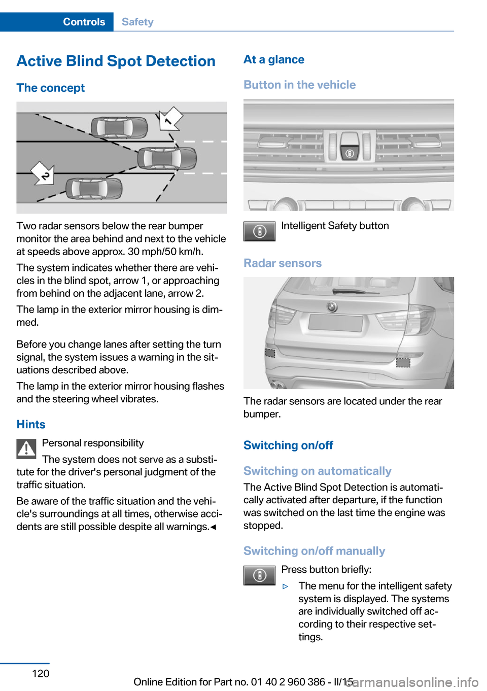
Two radar sensors below the rear bumper
monitor the area behind and next to the vehicle
at speeds above approx. 30 mph/50 km/h.
The system indicates whether there are vehi‐
cles in the blind spot, arrow 1, or approaching
from behind on the adjacent lane, arrow 2.
The lamp in the exterior mirror housing is dim‐
med.
Before you change lanes after setting the turn
signal, the system issues a warning in the sit‐
uations described above.
The lamp in the exterior mirror housing flashes
and the steering wheel vibrates.
Hints Personal responsibility
The system does not serve as a substi‐
tute for the driver's personal judgment of the
traffic situation.
Be aware of the traffic situation and the vehi‐
cle's surroundings at all times, otherwise acci‐
dents are still possible despite all warnings.◀
At a glance
Button in the vehicle
Intelligent Safety button
Radar sensors
The radar sensors are located under the rear
bumper.
Switching on/off
Switching on automatically The Active Blind Spot Detection is automati‐
cally activated after departure, if the function
was switched on the last time the engine was
stopped.
Switching on/off manually Press button briefly:
▷The menu for the intelligent safety
system is displayed. The systems
are individually switched off ac‐
cording to their respective set‐
tings.Seite 120ControlsSafety120
Online Edition for Part no. 01 40 2 960 386 - II/15
Page 125 of 257
▷LED lights up orange or goes out respec‐
tive to their individual settings.
Adjust as needed. Individual settings are
stored for the profile currently in use.
Press button again:
▷All Intelligent Safety systems are
activated.▷The LED lights up green.
Hold down button:
▷All Intelligent Safety systems are
turned off.▷The LED goes out.
Display
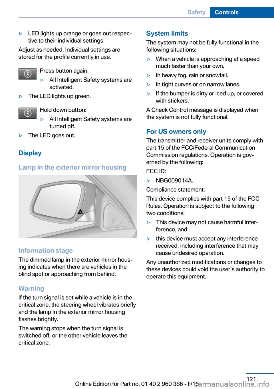
Lamp in the exterior mirror housing
Information stage
The dimmed lamp in the exterior mirror hous‐
ing indicates when there are vehicles in the
blind spot or approaching from behind.
Warning If the turn signal is set while a vehicle is in the
critical zone, the steering wheel vibrates briefly
and the lamp in the exterior mirror housing
flashes brightly.
The warning stops when the turn signal is
switched off, or the other vehicle leaves the
critical zone.
System limits
The system may not be fully functional in the
following situations:▷When a vehicle is approaching at a speed
much faster than your own.▷In heavy fog, rain or snowfall.▷In tight curves or on narrow lanes.▷If the bumper is dirty or iced up, or covered
with stickers.
A Check Control message is displayed when
the system is not fully functional.
For US owners only The transmitter and receiver units comply with
part 15 of the FCC/Federal Communication
Commission regulations. Operation is gov‐
erned by the following:
FCC ID:
▷NBG009014A.
Compliance statement:
This device complies with part 15 of the FCC
Rules. Operation is subject to the following
two conditions:
▷This device may not cause harmful inter‐
ference, and▷this device must accept any interference
received, including interference that may
cause undesired operation.
Any unauthorized modifications or changes to
these devices could void the user's authority to
operate this equipment.
Seite 121SafetyControls121
Online Edition for Part no. 01 40 2 960 386 - II/15
Page 129 of 257
xDrivexDrive is the all-wheel-drive system of your ve‐
hicle. Concerted action by the xDrive and DSC
further optimize traction and driving dynamics.
The xDrive all-wheel-drive system variably dis‐
tributes the drive forces to the front and rear
axles as demanded by the driving situation and
road surface.
Display on the Control Display
Displaying xDrive view1."Vehicle info"2."xDrive status"
The following information is displayed:
▷With a navigation system: compass display
for the driving direction▷Pitch attitude with degree and percentage▷Transverse gradient with degree indication▷Graphic display for the steering
HDC Hill Descent Control
The concept HDC is a downhill driving assistant that auto‐
matically controls vehicle speed on steep
downhill gradients. Without applying the
brakes, the vehicle moves at slightly more than
walking speed.
Hill Descent Control can be activated at
speeds below approx. 22 mph/35 km/h. When
driving downhill, the vehicle reduces its speed
to approx. walking speed and then keeps its
speed constant.
As long as there is active braking, the system
is on standby. The system does not brake the
vehicle during this time.
Only use HDC in low gears or in selector lever
position D or R.
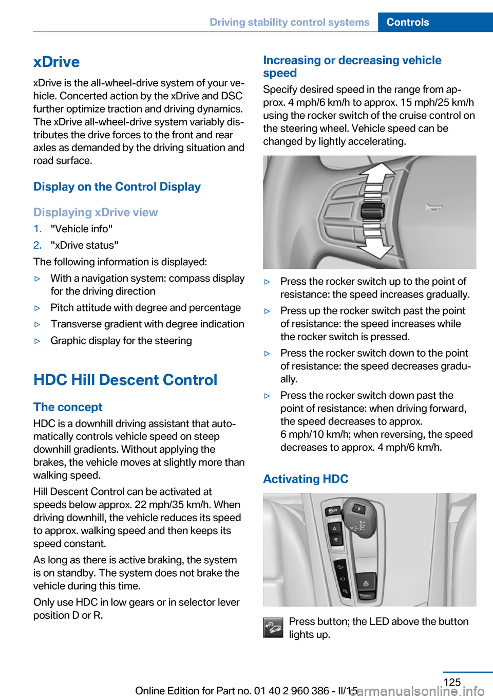
Increasing or decreasing vehicle
speed
Specify desired speed in the range from ap‐
prox. 4 mph/6 km/h to approx. 15 mph/25 km/h
using the rocker switch of the cruise control on
the steering wheel. Vehicle speed can be
changed by lightly accelerating.▷Press the rocker switch up to the point of
resistance: the speed increases gradually.▷Press up the rocker switch past the point
of resistance: the speed increases while
the rocker switch is pressed.▷Press the rocker switch down to the point
of resistance: the speed decreases gradu‐
ally.▷Press the rocker switch down past the
point of resistance: when driving forward,
the speed decreases to approx.
6 mph/10 km/h; when reversing, the speed
decreases to approx. 4 mph/6 km/h.
Activating HDC
Press button; the LED above the button
lights up.
Seite 125Driving stability control systemsControls125
Online Edition for Part no. 01 40 2 960 386 - II/15
Page 135 of 257
Before leaving the vehicle, secure it
against moving on its own.
Before leaving the vehicle with the engine run‐
ning: set the parking brake and ensure that the
Steptronic transmission is in position P. Other‐
wise, the vehicle may begin to move.◀
Overview
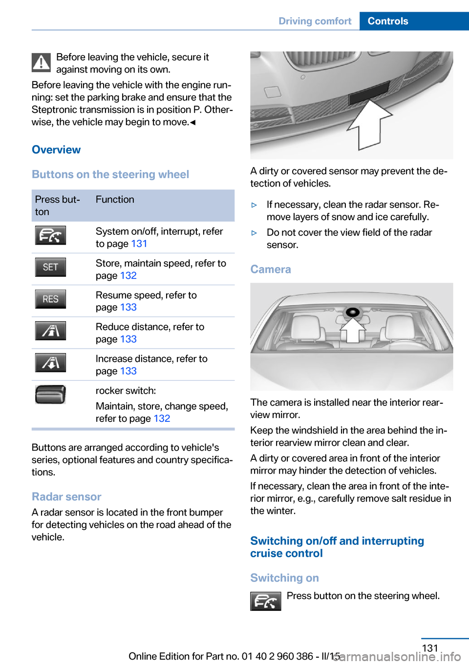
Buttons on the steering wheelPress but‐
tonFunctionSystem on/off, interrupt, refer
to page 131Store, maintain speed, refer to
page 132Resume speed, refer to
page 133Reduce distance, refer to
page 133Increase distance, refer to
page 133rocker switch:
Maintain, store, change speed,
refer to page 132
Buttons are arranged according to vehicle's
series, optional features and country specifica‐
tions.
Radar sensor
A radar sensor is located in the front bumper for detecting vehicles on the road ahead of the
vehicle.
A dirty or covered sensor may prevent the de‐
tection of vehicles.
▷If necessary, clean the radar sensor. Re‐
move layers of snow and ice carefully.▷Do not cover the view field of the radar
sensor.
Camera
The camera is installed near the interior rear‐
view mirror.
Keep the windshield in the area behind the in‐
terior rearview mirror clean and clear.
A dirty or covered area in front of the interior
mirror may hinder the detection of vehicles.
If necessary, clean the area in front of the inte‐
rior mirror, e.g., carefully remove salt residue in
the winter.
Switching on/off and interrupting
cruise control
Switching on Press button on the steering wheel.
Seite 131Driving comfortControls131
Online Edition for Part no. 01 40 2 960 386 - II/15
Page 141 of 257
Cruise controlThe concept The system maintains a preset speed via the
buttons on the steering wheel. The system
brakes on downhill gradients if engine braking
is insufficient.
General information
Depending on the driving settings, the features
of the cruise control can change in certain
areas.
Hints Unfavorable conditions
Do not use the system if unfavorable
conditions make it impossible to drive at a con‐
stant speed, e.g.:▷On winding roads.▷In heavy traffic.▷On slippery roads, in fog, snow or rain, or
on a loose road surface.
Otherwise, you could lose control of the vehi‐
cle and cause an accident.◀
Overview
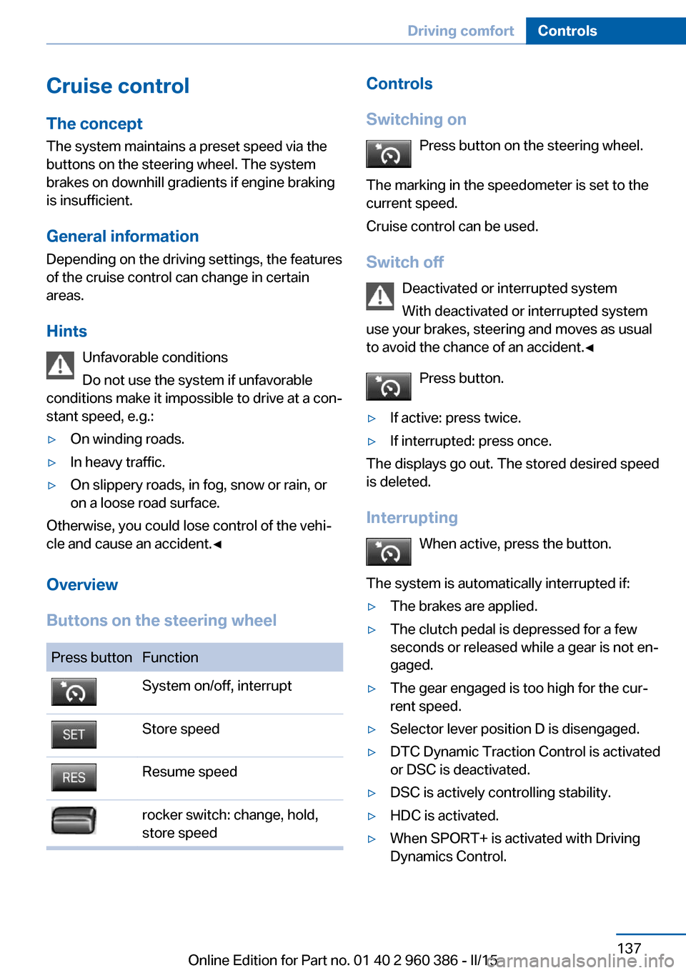
Buttons on the steering wheel
Press buttonFunctionSystem on/off, interruptStore speedResume speedrocker switch: change, hold,
store speedControls
Switching on Press button on the steering wheel.
The marking in the speedometer is set to the
current speed.
Cruise control can be used.
Switch off Deactivated or interrupted system
With deactivated or interrupted system
use your brakes, steering and moves as usual
to avoid the chance of an accident.◀
Press button.▷If active: press twice.▷If interrupted: press once.
The displays go out. The stored desired speed
is deleted.
Interrupting When active, press the button.
The system is automatically interrupted if:
▷The brakes are applied.▷The clutch pedal is depressed for a few
seconds or released while a gear is not en‐
gaged.▷The gear engaged is too high for the cur‐
rent speed.▷Selector lever position D is disengaged.▷DTC Dynamic Traction Control is activated
or DSC is deactivated.▷DSC is actively controlling stability.▷HDC is activated.▷When SPORT+ is activated with Driving
Dynamics Control.Seite 137Driving comfortControls137
Online Edition for Part no. 01 40 2 960 386 - II/15
Page 152 of 257
Parking assistantThe concept
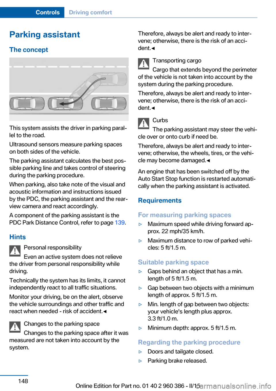
This system assists the driver in parking paral‐
lel to the road.
Ultrasound sensors measure parking spaces
on both sides of the vehicle.
The parking assistant calculates the best pos‐
sible parking line and takes control of steering
during the parking procedure.
When parking, also take note of the visual and
acoustic information and instructions issued
by the PDC, the parking assistant and the rear‐
view camera and react accordingly.
A component of the parking assistant is the
PDC Park Distance Control, refer to page 139.
Hints Personal responsibility
Even an active system does not relieve
the driver from personal responsibility while
driving.
Technically the system has its limits, it cannot
independently react to all traffic situations.
Monitor your driving, be on the alert, observe
the vehicle surroundings and other traffic and
react when needed - risk of accident.◀
Changes to the parking space
Changes to the parking space after it was
measured are not taken into account by the
system.
Therefore, always be alert and ready to inter‐
vene; otherwise, there is the risk of an acci‐
dent.◀
Transporting cargo
Cargo that extends beyond the perimeter
of the vehicle is not taken into account by the
system during the parking procedure.
Therefore, always be alert and ready to inter‐
vene; otherwise, there is the risk of an acci‐
dent.◀
Curbs
The parking assistant may steer the vehi‐
cle over or onto curb if need be.
Therefore, always be alert and ready to inter‐
vene; otherwise, the wheels, tires, or the vehi‐
cle may become damaged.◀
An engine that has been switched off by the
Auto Start Stop function is restarted automati‐
cally when the parking assistant is activated.
Requirements
For measuring parking spaces▷Maximum speed while driving forward ap‐
prox. 22 mph/35 km/h.▷Maximum distance to row of parked vehi‐
cles: 5 ft/1.5 m.
Suitable parking space
▷Gaps behind an object that has a min.
length of 5 ft/1.5 m.▷Gap between two objects with a minimum
length of approx. 5 ft/1.5 m.▷Min. length of gap between two objects:
your vehicle's length plus approx.
3.3 ft/1.0 m.▷Minimum depth: approx. 5 ft/1.5 m.
Regarding the parking procedure
▷Doors and tailgate closed.▷Parking brake released.Seite 148ControlsDriving comfort148
Online Edition for Part no. 01 40 2 960 386 - II/15
Page 154 of 257
▷Control Display shows suitable parking
spaces at the edge of the road next to the
vehicle symbol. When the parking assistant
is active, suitable parking spaces are high‐
lighted.▷The parking procedure is ac‐
tive. Steering control has
been taken over by system.▷Parking space search is always active
whenever the vehicle is moving forward
slow and straight, even if the system is de‐
activated. When the system is deactivated,
the displays on the Control Display are
shown in gray.
Parking using the parking assistant
Check the traffic situation as well
Louds noises outside and inside the ve‐
hicle can drown out the parking assistant's and
PDC's signals.
Check the traffic situation around the vehicle
with your own eyes; otherwise, there is a dan‐
ger of an accident.◀
1.Switch on the parking assistant and acti‐
vate it if needed.
The status of the parking space search is
indicated on the Control Display.2.Follow the instructions on the Control Dis‐
play.
The best possible parking position will
come after gear change on the stationary
vehicle - wait for the automatic steering
wheel move.
The end of the parking procedure is indi‐
cated on the Control Display.3.Adjust the parking position yourself if
needed.
Interrupting manually
The parking assistant can be interrupted at any
time:
▷ "Parking Assistant" Select the symbol
on the Control Display.▷Press button.
Interrupting automatically
The system is interrupted automatically in the
following situations:
▷If the driver grasps the steering wheel or if
he takes over steering.▷If a gear is selected that does not match
the instruction on the Control Display.▷If the vehicle speed exceeds approx.
6 mph/10 km/h.▷Possible on snow-covered or slippery road
surfaces.▷When there are obstacles that are hard to
overcome, such as curbs.▷When there are obstacles that suddenly
arise.▷If the Park Distance Control PDC displays
clearances that are too small.▷If a maximum number of parking attempts
or the time taken for parking is exceeded.▷When switching to another function on the
Control Display.
A Check Control message is displayed.
Resume An interrupted parking procedure can be con‐
tinued if needed.
Follow the instructions on the Control Display
to do this.
System limits
No parking assistance
The parking assistant does not offer assis‐
tance in the following situations:
▷In tight curves.Seite 150ControlsDriving comfort150
Online Edition for Part no. 01 40 2 960 386 - II/15