lock BMW X3 2016 F25 Service Manual
[x] Cancel search | Manufacturer: BMW, Model Year: 2016, Model line: X3, Model: BMW X3 2016 F25Pages: 257, PDF Size: 5.26 MB
Page 172 of 257
Storage compartmentsVehicle features and optionsThis chapter describes all standard, country-
specific and optional features offered with the
series. It also describes features that are not
necessarily available in your car, e. g., due to
the selected options or country versions. This
also applies to safety-related functions and
systems. The respectively applicable country
provisions must be observed when using the
respective features and systems.
Hints No loose objects in the car's interior
Do not stow any objects in the car's inte‐
rior without securing them; otherwise, they
may present a danger to occupants e.g., during
braking and evasive maneuvers.◀
Do not place anti-slip mats on the dash‐
board
Do not place anti-slip mats on the dashboard.
The mat materials could damage the dash‐
board.◀
Storage compartments The following storage compartments are avail‐
able in the vehicle interior:▷Glove compartment on the front passenger
side, refer to page 168.▷Storage compartment in the front center
armrest, refer to page 169.▷Compartments in the doors, refer to
page 169.▷Pockets on the backrests of the front
seats.▷Net in the front passenger footwell.Glove compartment
Front passenger side
Note Close the glove compartment again im‐
mediately
Close the glove compartment immediately af‐
ter use while driving; otherwise, injury may oc‐
cur during accidents.◀
Opening
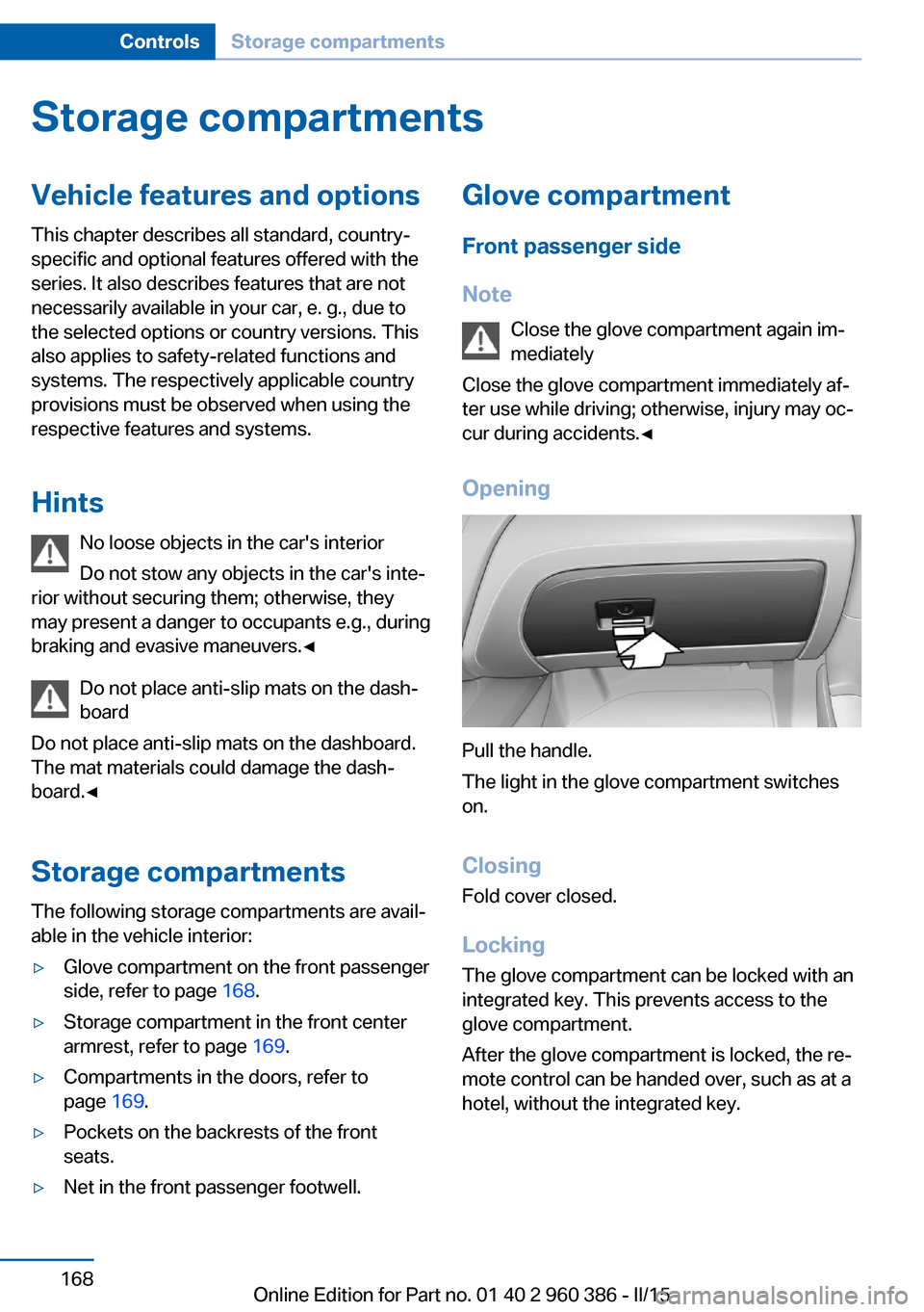
Pull the handle.
The light in the glove compartment switches
on.
ClosingFold cover closed.
Locking
The glove compartment can be locked with an
integrated key. This prevents access to the
glove compartment.
After the glove compartment is locked, the re‐
mote control can be handed over, such as at a
hotel, without the integrated key.
Seite 168ControlsStorage compartments168
Online Edition for Part no. 01 40 2 960 386 - II/15
Page 194 of 257

RefuelingVehicle features and options
This chapter describes all standard, country-
specific and optional features offered with the
series. It also describes features that are not
necessarily available in your car, e. g., due to
the selected options or country versions. This
also applies to safety-related functions and
systems. The respectively applicable country
provisions must be observed when using the
respective features and systems.
Hints Observe the fuel recommendation, refer to
page 192, prior to refueling.
Refuel promptly
Refuel no later than at a range of
30 miles/50 km or engine operation might fail
and damage might occur.◀
Diesel engines The filler neck is designed for refueling at die‐
sel fuel pumps.
Fuel lid Opening1.Briefly press the rear edge of the fuel filler
flap.2.Turn the tank lid counterclockwise.3.Place the tank lid in the bracket attached to
the fuel filler flap.
Closing
1.Fit the lid and turn it clockwise until you
clearly hear a click.2.Close the fuel filler flap.
Do not pinch the retaining strap
Do not pinch the retaining strap attached
to the lid; otherwise, the lid cannot be closed
properly and fuel vapors can escape.◀
Manually unlocking fuel filler flap In the event of an electrical malfunction, e.g.
The release is located in the trunk.
Seite 190MobilityRefueling190
Online Edition for Part no. 01 40 2 960 386 - II/15
Page 199 of 257

exhaust fluid can be replenished simply
and safely.▷Alternative: NOx reduction agent AUS 32
Diesel exhaust fluid can be purchased at your
service center.
Refill quantity
When the Reserve display starts, add at least
3 bottles of reducing agent.
This corresponds to approx. 1.5 US gal/6 liters.
Tank for reducing agent
The tank for the reducing agent is located next
to the fuel tank.
Adding the reducing agent Add the reducing agent when the ignition is
switched on.
1.Open the fuel filler flap, refer to page 190.2.Turn the tank lid counterclockwise and re‐
move.3.Place the bottle on it and turn it as far as it
will go, see arrow.4.Press the bottle down, see arrow.The vehicle tank will be filled.
The tank is full when the fill level in the bot‐
tle no longer changes. It is not possible to
overfill.5.Pull back the bottle, see arrow, and un‐
screw it.6.Replace the tank lid and turn it clockwise.7.Close the fuel filler flap.
After adding Diesel exhaust fluid
Note Incorrect fluids
After filling with incorrect fluids, such as
antifreeze for washer fluid, do not start the en‐
gine, otherwise there is risk of fire.◀
Contact your service center.
Disposing of bottles You take your empty Diesel exhaust
fluid bottles to your service center for
disposal.
Seite 195FuelMobility195
Online Edition for Part no. 01 40 2 960 386 - II/15
Page 213 of 257
Never reach into the engine compart‐
ment
Never reach into spaces or gaps in the engine
compartment; otherwise, there is a risk of in‐
jury, e.g., from rotating or hot parts.◀
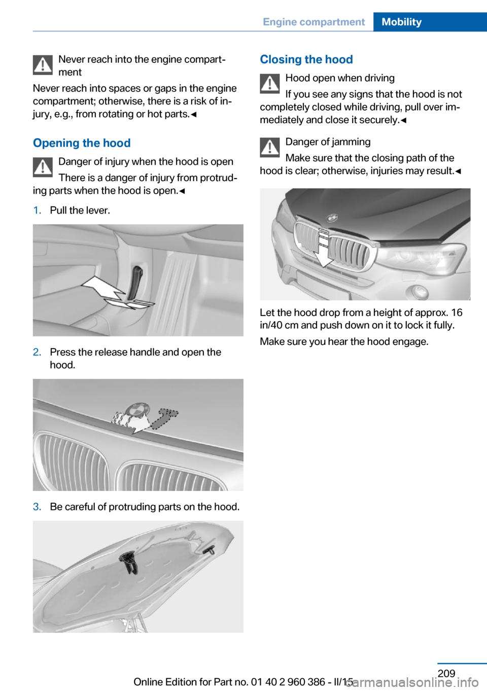
Opening the hood Danger of injury when the hood is open
There is a danger of injury from protrud‐
ing parts when the hood is open.◀1.Pull the lever.2.Press the release handle and open the
hood.3.Be careful of protruding parts on the hood.Closing the hood
Hood open when driving
If you see any signs that the hood is not
completely closed while driving, pull over im‐
mediately and close it securely.◀
Danger of jamming
Make sure that the closing path of the
hood is clear; otherwise, injuries may result.◀
Let the hood drop from a height of approx. 16
in/40 cm and push down on it to lock it fully.
Make sure you hear the hood engage.
Seite 209Engine compartmentMobility209
Online Edition for Part no. 01 40 2 960 386 - II/15
Page 217 of 257
CoolantVehicle features and optionsThis chapter describes all standard, country-
specific and optional features offered with the
series. It also describes features that are not
necessarily available in your car, e. g., due to
the selected options or country versions. This
also applies to safety-related functions and
systems. The respectively applicable country
provisions must be observed when using the
respective features and systems.
Hints Danger of burns from hot engine
Do not open the cooling system while
the engine is hot; otherwise, esliding coolant
may cause burns.◀
Suitable additives
Only use suitable additives; otherwise,
engine damage may occur. The additives are
harmful to your health.◀
Coolant consists of water and additives.
Not all commercially available additives are
suitable for the vehicle. Information about the
suitable additives are available from the service
center.
Coolant level
General information
Depending on the engine installation, the cool‐
ant reservoir is located on the right side or the
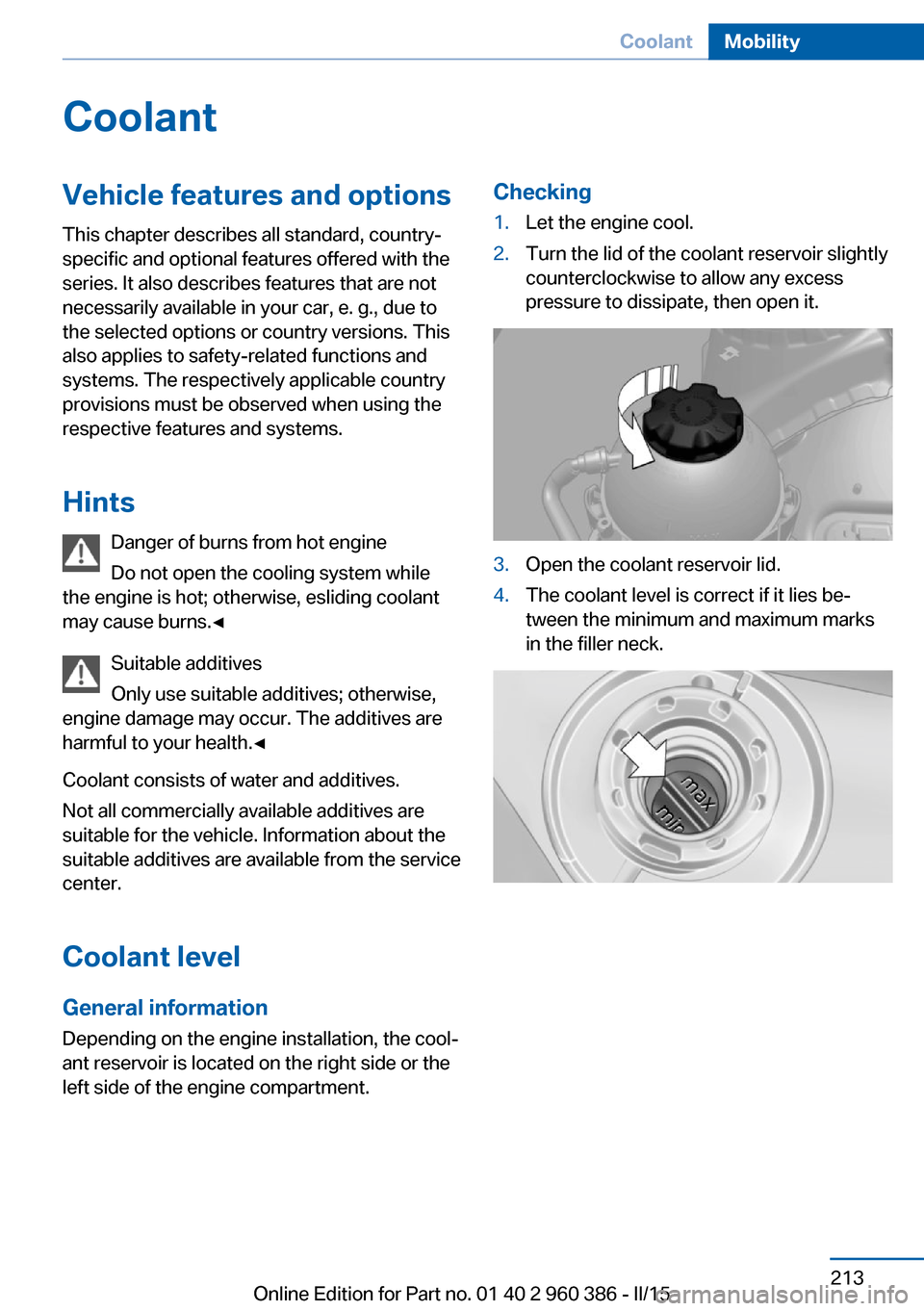
left side of the engine compartment.Checking1.Let the engine cool.2.Turn the lid of the coolant reservoir slightly
counterclockwise to allow any excess
pressure to dissipate, then open it.3.Open the coolant reservoir lid.4.The coolant level is correct if it lies be‐
tween the minimum and maximum marks
in the filler neck.Seite 213CoolantMobility213
Online Edition for Part no. 01 40 2 960 386 - II/15
Page 218 of 257

Adding1.Let the engine cool.2.Turn the lid of the coolant reservoir slightly
counterclockwise to allow any excess
pressure to dissipate, then open it.3.If the coolant is low, slowly add coolant up
to the specified level; do not overfill.4.Turn the lid until there is an audible click.
The arrows on the coolant reservoir and
the lid must point towards one another.5.Have the cause of the coolant loss elimi‐
nated as soon as possible.
Disposal
Comply with the relevant environmen‐
tal protection regulations when dispos‐
ing of coolant and coolant additives.
Seite 214MobilityCoolant214
Online Edition for Part no. 01 40 2 960 386 - II/15
Page 221 of 257

Replacing componentsVehicle features and optionsThis chapter describes all standard, country-
specific and optional features offered with the
series. It also describes features that are not
necessarily available in your car, e. g., due to
the selected options or country versions. This
also applies to safety-related functions and
systems. The respectively applicable country
provisions must be observed when using the
respective features and systems.
Onboard vehicle tool kit
The onboard vehicle tool kit is located under
the first aid kit behind the left folding cover in
the trunk.
Wiper blade replacement
Hints Do not fold down the wipers without
wiper blades
Do not fold down the wipers if wiper blades
have not been installed; this may damage the
windshield.◀
Front: Replacing the wiper blades1.To change the wiper blades, fold up, refer
to page 75, the wiper arms.2.Fold up the wipers.3.Position the wiper blade in a horizontal po‐
sition.4.Remove the wiper blade toward one side.5.Insert the new wiper blade in reverse order
of removal until it locks in place.6.Fold down the wipers.Seite 217Replacing componentsMobility217
Online Edition for Part no. 01 40 2 960 386 - II/15
Page 223 of 257
lights' settings checked and corrected by serv‐
ice after a replacement.
Front lights, bulb replacement
Halogen headlights
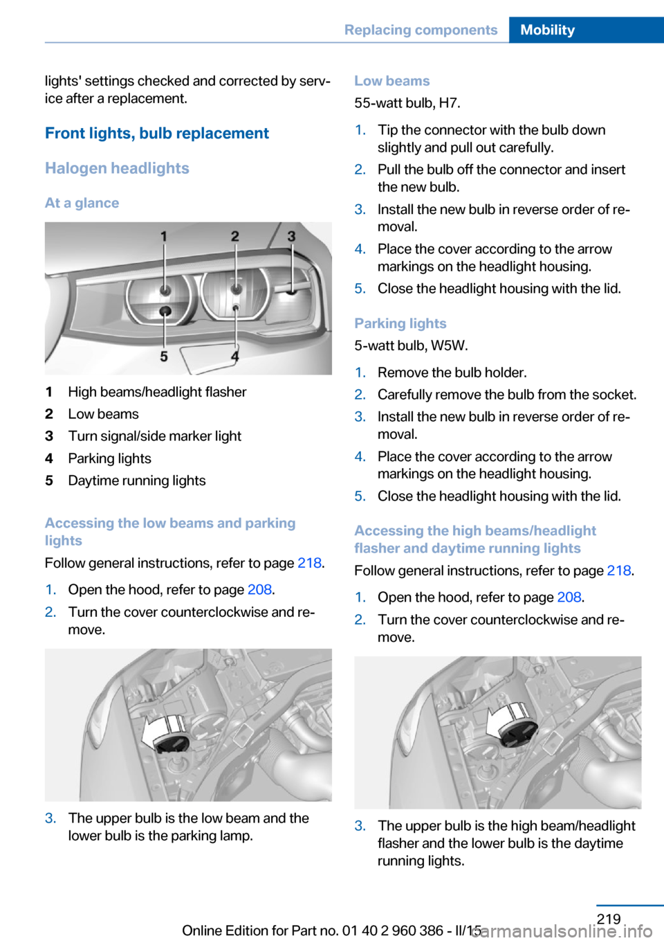
At a glance1High beams/headlight flasher2Low beams3Turn signal/side marker light4Parking lights5Daytime running lights
Accessing the low beams and parking
lights
Follow general instructions, refer to page 218.
1.Open the hood, refer to page 208.2.Turn the cover counterclockwise and re‐
move.3.The upper bulb is the low beam and the
lower bulb is the parking lamp.Low beams
55-watt bulb, H7.1.Tip the connector with the bulb down
slightly and pull out carefully.2.Pull the bulb off the connector and insert
the new bulb.3.Install the new bulb in reverse order of re‐
moval.4.Place the cover according to the arrow
markings on the headlight housing.5.Close the headlight housing with the lid.
Parking lights
5-watt bulb, W5W.
1.Remove the bulb holder.2.Carefully remove the bulb from the socket.3.Install the new bulb in reverse order of re‐
moval.4.Place the cover according to the arrow
markings on the headlight housing.5.Close the headlight housing with the lid.
Accessing the high beams/headlight
flasher and daytime running lights
Follow general instructions, refer to page 218.
1.Open the hood, refer to page 208.2.Turn the cover counterclockwise and re‐
move.3.The upper bulb is the high beam/headlight
flasher and the lower bulb is the daytime
running lights.Seite 219Replacing componentsMobility219
Online Edition for Part no. 01 40 2 960 386 - II/15
Page 224 of 257
High beams/headlight flasher
55-watt bulb, H7.1.Tip the connector with the bulb up slightly
and pull out carefully.2.Pull the bulb off the connector and insert
the new bulb.3.Install the new bulb in reverse order of re‐
moval.4.Place the cover according to the arrow
markings on the headlight housing.5.Close the headlight housing with the lid.
Daytime running lights
21-watt bulb, W21W.
1.Turn the bulb holder counterclockwise and
remove.2.Carefully remove the bulb from the socket.3.Install the new bulb in reverse order of re‐
moval.4.Place the cover according to the arrow
markings on the headlight housing.5.Close the headlight housing with the lid.
Xenon headlights
Hints
Because of the long life of these bulbs, the
likelihood of failure is very low. Switching the
lights on and off frequently shortens their life.
If a bulb fails, reel on the front fog lights and
continue the trip with great care. Comply with
local regulations.
Do not perform work/bulb replacement
on xenon headlights
Have any work on the xenon lighting system,
including bulb replacement, performed only by
a service center. Due to the high voltage
present in the system, there is a danger of fatal
injuries if work is carried out improperly.◀
For checking and adjusting headlamp aim,
please contact your BMW center.
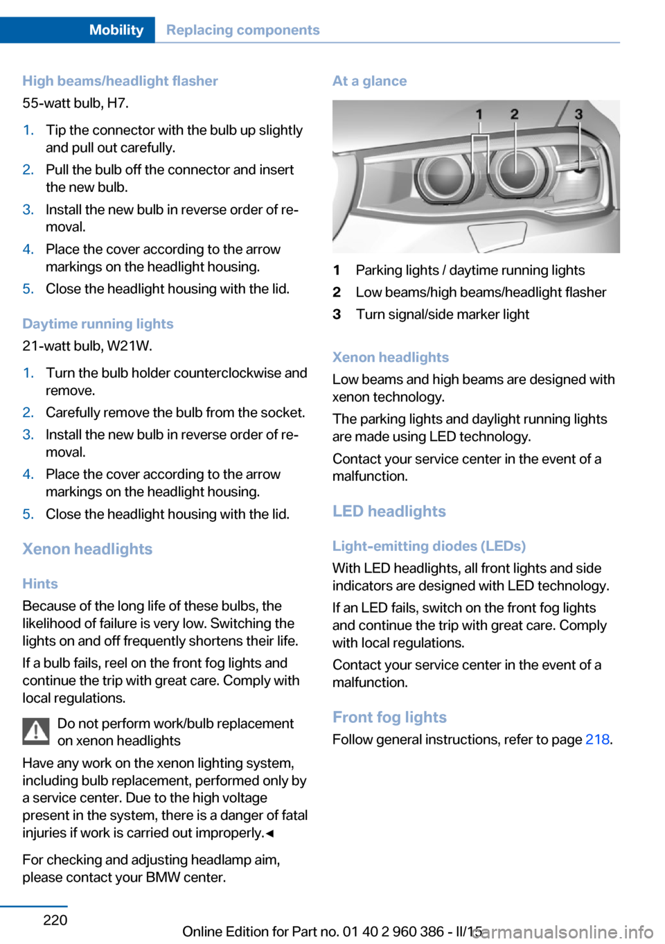
At a glance1Parking lights / daytime running lights2Low beams/high beams/headlight flasher3Turn signal/side marker light
Xenon headlights
Low beams and high beams are designed with
xenon technology.
The parking lights and daylight running lights
are made using LED technology.
Contact your service center in the event of a
malfunction.
LED headlightsLight-emitting diodes (LEDs)
With LED headlights, all front lights and side
indicators are designed with LED technology.
If an LED fails, switch on the front fog lights and continue the trip with great care. Complywith local regulations.
Contact your service center in the event of a
malfunction.
Front fog lights
Follow general instructions, refer to page 218.
Seite 220MobilityReplacing components220
Online Edition for Part no. 01 40 2 960 386 - II/15
Page 225 of 257
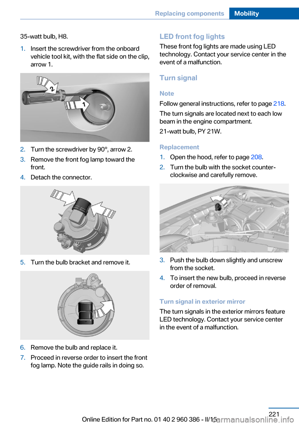
35-watt bulb, H8.1.Insert the screwdriver from the onboard
vehicle tool kit, with the flat side on the clip,
arrow 1.2.Turn the screwdriver by 90°, arrow 2.3.Remove the front fog lamp toward the
front.4.Detach the connector.5.Turn the bulb bracket and remove it.6.Remove the bulb and replace it.7.Proceed in reverse order to insert the front
fog lamp. Note the guide rails in doing so.LED front fog lights
These front fog lights are made using LED
technology. Contact your service center in the
event of a malfunction.
Turn signal Note
Follow general instructions, refer to page 218.
The turn signals are located next to each low
beam in the engine compartment.
21-watt bulb, PY 21W.
Replacement1.Open the hood, refer to page 208.2.Turn the bulb with the socket counter‐
clockwise and carefully remove.3.Push the bulb down slightly and unscrew
from the socket.4.To insert the new bulb, proceed in reverse
order of removal.
Turn signal in exterior mirror
The turn signals in the exterior mirrors feature
LED technology. Contact your service center
in the event of a malfunction.
Seite 221Replacing componentsMobility221
Online Edition for Part no. 01 40 2 960 386 - II/15