ESP BMW X3 3.0I 2006 E83 User Guide
[x] Cancel search | Manufacturer: BMW, Model Year: 2006, Model line: X3 3.0I, Model: BMW X3 3.0I 2006 E83Pages: 133, PDF Size: 8.37 MB
Page 44 of 133
Driving
42 Do not use the cruise control under unfa-
vorable conditions that do not permit a
constant speed, e.g. when driving on winding
roads or in heavy traffic or when negotiating
poor road conditions such as snow, rain, ice, or
a loose road surface. Otherwise, you could lose
control of the vehicle and cause an accident.<
Indicator lamp
The indicator lamp lights up green:
System ready for operation using the
buttons on the steering wheel.
Activating system
As of ignition key position 2:
Press button on steering wheel; the indicator
lamp in the instrument cluster comes on. You
are able to use the cruise control.
Deactivating system
Press the button repeatedly until the indicator
lamp in the instrument cluster goes out.
The cruise control is also deactivated when the
ignition key is turned to position 0. The speed
stored in the memory is deleted in the process.
Maintaining speed, storing, and
accelerating
Briefly press + button:
The system maintains and stores the current
vehicle speed. Each additional touch of the but-
ton increases the speed by approx. 1 mph/
1km/h.
Press and hold + button:
The vehicle accelerates without pressure on
the accelerator pedal. When you release the
button, the system maintains and stores the
current speed.If the braking action of the engine is insufficient
on a downhill stretch, the controlled speed can
be exceeded. Speed can drop on uphill grades if
the engine output is insufficient.
Decelerating
Briefly press – button:
Each press of the button decreases the vehi-
cle's speed by roughly 1 mph/1 km/h, provided
that you have already activated the cruise con-
trol.
Press and hold – button:
With the cruise control active, the system auto-
matically reduces the fuel supply to slow the
vehicle. When you release the button, the sys-
tem maintains and stores the current speed.
Interrupting cruise control
When the system is activated, press button 1.
The indicator lamp stays on. You can use the
cruise control again whenever required by
requesting the speed that was stored last.
In addition, the system is automatically inter-
rupted in response to the following conditions:
>When you apply pressure to the brake pedal
>When you apply pressure to the clutch
pedal or when you move the automatic
transmission selector lever from D to N
>If you exceed or fall below the controlled
speed for an extended period, by pressing
the accelerator, for example
>When DSC is activated
Resuming stored speed
Press button:
The vehicle accelerates to and maintains the
last speed stored.
Page 50 of 133
Technology for comfort, convenience and safety
48
Malfunction
The LED in the button flashes and a short con-
tinuous tone sounds. PDC is malfunctioning.
Switch off PDC. Have the system checked.
To prevent this problem, keep the sensors
clean and free of ice or snow in order to ensure
that they will continue to operate effectively.
When using high-pressure washers, do not
spray sensors for long periods and keep the
sprayer at least 4 in/10 cm away from the sen-
sors.
System limits
Even with PDC, final responsibility for
estimating the distance between the
vehicle and any obstructions always remains
with the driver. Even when sensors are involved,
there is a blind spot in which objects cannot be
detected. The system is also subject to the
physical limits that apply to all forms of ultra-
sonic measurement, such as those encoun-
tered with tow bars and trailer couplings, or thin
and wedge-shaped objects, etc. Low objects
already displayed, e.g. a curb, can come into the
blind spot of the sensors before a continuous
tone sounds. The system may fail to detect
higher obstacles such as ledges.
Loud sources of sound, inside and outside the
vehicle, could drown out the PDC signal tone.<
Driving stability control
systems
Your BMW is equipped with an extended array
of systems designed to enhance and maintain
vehicle stability even under unfavorable driving
conditions.
ABS Antilock Brake System
ABS prevents the wheels from locking during
braking. Safe steering response is maintained
even during full braking. This results in an
increase in the active safety.
ABS is operational every time you start the
engine. Safe braking, refer to page78.
Electronic brake-force distribution
The system controls the brake pressure in the
rear wheels to ensure a stable braking behavior.
DBC Dynamic Brake Control
When the brake pedal is depressed quickly, this
system automatically generates a maximum
braking force distribution and thus helps keep
the braking distance to a minimum during full
braking. This system exploits all of the benefits
provided by ABS.
As long as you want full braking to continue, do
not reduce pressure on the brake.
DSC Dynamic Stability Control
DSC prevents slip at the drive wheels when
starting off and accelerating. DSC also detects
unstable driving conditions, such as a fishtailing
of the vehicle's rear end or the sliding of the
vehicle on its front wheels. In these circum-
stances, DSC helps keep the vehicle on a safe
path, within physical limits, by reducing engine
output and by applying the brakes in individual
wheels.
The DSC is operational every time you start the
engine.
The laws of physics cannot be repealed,
even with DSC. An appropriate driving
style always remains the responsibility of the
driver. Do not reduce the additional safety mar-
gin again by taking unnecessary risks.<
Indicator lamp
The indicator lamp goes out shortly
after the engine starts.
When the indicator lamp flashes:
DSC is controlling the drive and braking forces.
When the indicator lamp stays lit:
DSC has been switched off with the button.
Page 55 of 133
Reference
At a glance
Controls
Driving tips
Mobility
53
Have the damaged tire replaced by your BMW
Sports Activity Vehicle Center or a workshop
that is familiar with TPM and works in accor-
dance with BMW repair procedures, using
appropriately trained personnel.
Malfunction
The yellow warning lamp flashes and
then lights up continuously. Flat tires
cannot be detected.
Such a message is displayed in the following
situations:
>In the event of a malfunction:
Have the system checked
>When a wheel without TPM electronics is
mounted, e.g. a compact wheel
>When TPM is experiencing temporary inter-
ference from other systems or devices that
use the same frequency
Brake force display
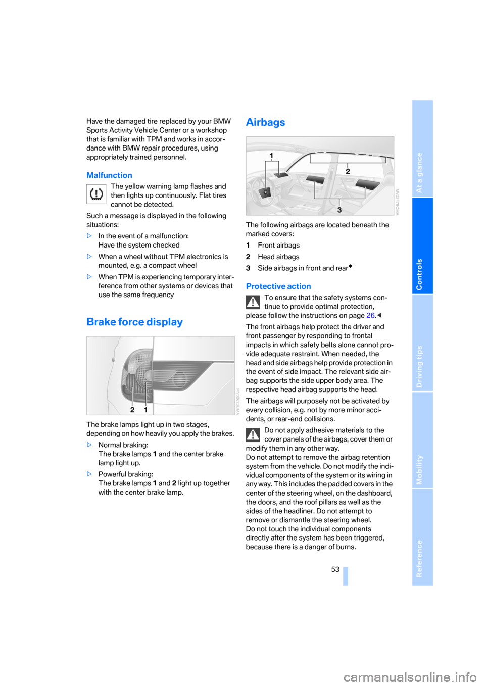
The brake lamps light up in two stages,
depending on how heavily you apply the brakes.
>Normal braking:
The brake lamps 1 and the center brake
lamp light up.
>Powerful braking:
The brake lamps 1 and 2 light up together
with the center brake lamp.
Airbags
The following airbags are located beneath the
marked covers:
1Front airbags
2Head airbags
3Side airbags in front and rear
*
Protective action
To ensure that the safety systems con-
tinue to provide optimal protection,
please follow the instructions on page26.<
The front airbags help protect the driver and
front passenger by responding to frontal
impacts in which safety belts alone cannot pro-
vide adequate restraint. When needed, the
head and side airbags help provide protection in
the event of side impact. The relevant side air-
bag supports the side upper body area. The
respective head airbag supports the head.
The airbags will purposely not be activated by
every collision, e.g. not by more minor acci-
dents, or rear-end collisions.
Do not apply adhesive materials to the
cover panels of the airbags, cover them or
modify them in any other way.
Do not attempt to remove the airbag retention
system from the vehicle. Do not modify the indi-
vidual components of the system or its wiring in
any way. This includes the padded covers in the
center of the steering wheel, on the dashboard,
the doors, and the roof pillars as well as the
sides of the headliner. Do not attempt to
remove or dismantle the steering wheel.
Do not touch the individual components
directly after the system has been triggered,
because there is a danger of burns.
Page 56 of 133
Technology for comfort, convenience and safety
54 In the event of malfunctions, deactivation, or
triggering of the airbag restraint system, have
the testing, repair, removal, and disposal of air-
bag generators executed only by a BMW Sports
Activity Vehicle Center or a workshop that
works according to BMW repair procedures
with correspondingly trained personnel and has
the required explosives licenses. Unprofes-
sional attempts to service the system could
lead to failure in an emergency or undesired air-
bag activation, either of which could result in
personal injury.<
Airbag warnings and information are also pro-
vided on the sun visors.
Automatic deactivation of front
passenger airbags
By evaluating the pressure on the seat cushion
of the front passenger seat, the system detects
whether or not the seat is occupied. The front
and side airbags for the passenger are activated
or deactivated by the system accordingly.
The indicator lamp located above the
inside rearview mirror indicates whether
the front passenger airbag system is currently
deactivated or activated, refer to Status of pas-
senger airbag in the section below.<
Before transporting a child in the front
passenger seat, follow the safety notices
and instructions under Transporting children
safely, refer to page33.
When teenagers or adults assume certain sit-
ting positions, the front and side airbags on the
passenger side can deactivate; this causes the
indicator lamp for the front passenger airbag to
light up. If this happens, have them change their
sitting position so that the passenger airbag is
activated and the indicator lamp goes out. If the
desired status cannot be achieved by changing
their sitting position, then have the person ride
in the back. Do not attach seat covers, seat
cushion padding, ball mats or other items to the
passenger seat unless they are specifically rec-
ommended by BMW. Do not place any items
under the seat which could press against the
seat from below. Otherwise, a correct analysis
of the seat cushion is not ensured.<
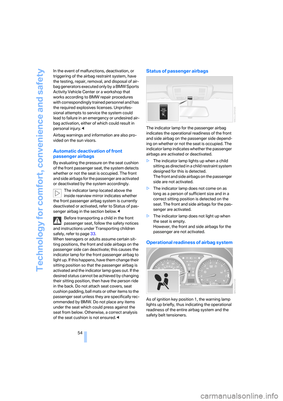
Status of passenger airbags
The indicator lamp for the passenger airbag
indicates the operational readiness of the front
and side airbag on the passenger side depend-
ing on whether or not the seat is occupied. The
indicator lamp indicates whether the passenger
airbags are activated or deactivated.
>The indicator lamp lights up when a child
sitting as directed in a child restraint system
designed for this is detected.
The front and side airbags on the passenger
side are not activated.
>The indicator lamp does not come on as
long as a person of sufficient size and in a
correct sitting position is detected on the
seat. The front and side airbags for the pas-
senger are activated.
>The indicator lamp does not light up when
the seat is empty.
However, the front and side airbags for the
passenger are not activated.
Operational readiness of airbag system
As of ignition key position 1, the warning lamp
lights up briefly, thus indicating the operational
readiness of the entire airbag system and the
safety belt tensioners.
Page 57 of 133

Reference
At a glance
Controls
Driving tips
Mobility
55
Airbag system malfunction
>Warning lamp does not come on with the
ignition key in position 1 or higher.
>The warning lamp lights up continuously.
Have the airbag system checked immedi-
ately if a malfunction occurs; otherwise,
there is a danger of the system failing to
respond in the expected manner to an impact
occurring within its normal response range.<
Page 58 of 133
Lamps
56
Lamps
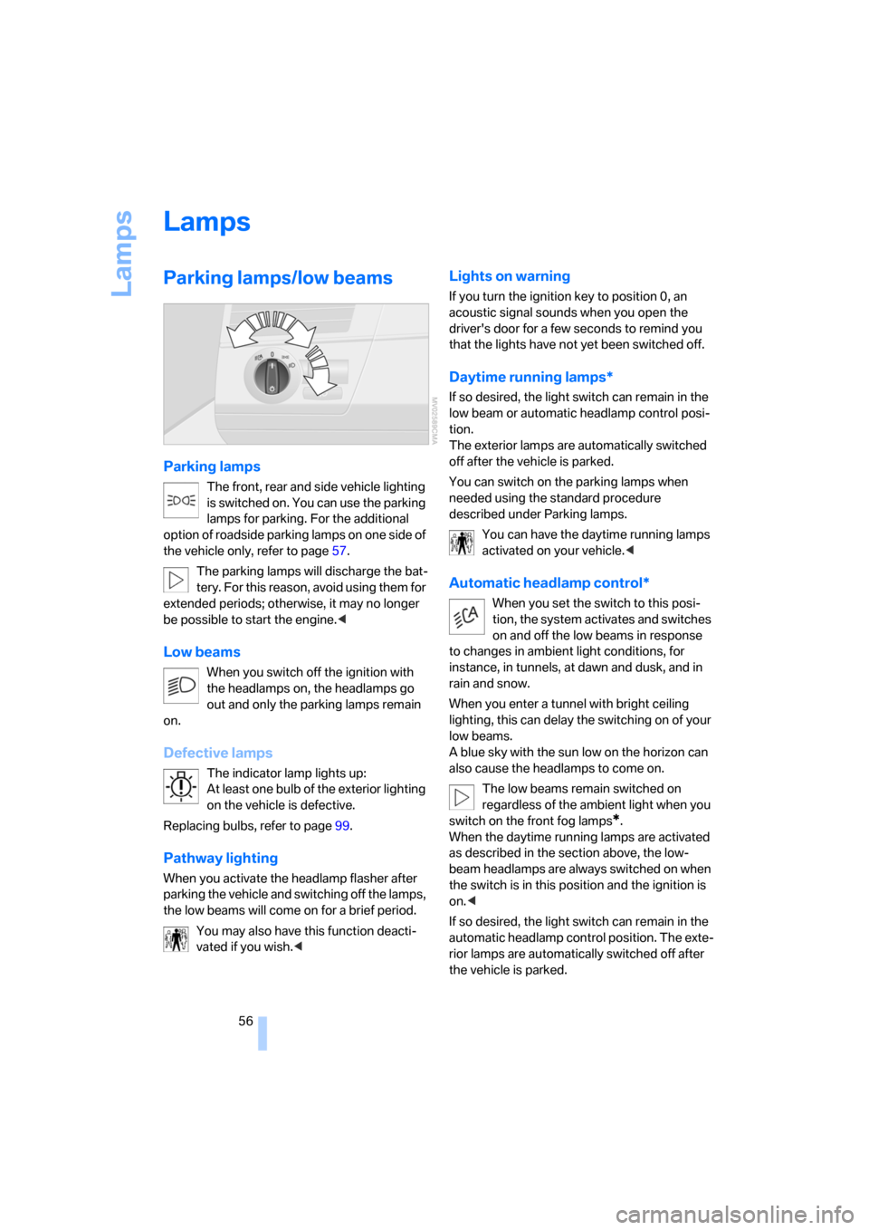
Parking lamps/low beams
Parking lamps
The front, rear and side vehicle lighting
is switched on. You can use the parking
lamps for parking. For the additional
option of roadside parking lamps on one side of
the vehicle only, refer to page57.
The parking lamps will discharge the bat-
tery. For this reason, avoid using them for
extended periods; otherwise, it may no longer
be possible to start the engine.<
Low beams
When you switch off the ignition with
the headlamps on, the headlamps go
out and only the parking lamps remain
on.
Defective lamps
The indicator lamp lights up:
At least one bulb of the exterior lighting
on the vehicle is defective.
Replacing bulbs, refer to page99.
Pathway lighting
When you activate the headlamp flasher after
parking the vehicle and switching off the lamps,
the low beams will come on for a brief period.
You may also have this function deacti-
vated if you wish.<
Lights on warning
If you turn the ignition key to position 0, an
acoustic signal sounds when you open the
driver's door for a few seconds to remind you
that the lights have not yet been switched off.
Daytime running lamps*
If so desired, the light switch can remain in the
low beam or automatic headlamp control posi-
tion.
The exterior lamps are automatically switched
off after the vehicle is parked.
You can switch on the parking lamps when
needed using the standard procedure
described under Parking lamps.
You can have the daytime running lamps
activated on your vehicle.<
Automatic headlamp control*
When you set the switch to this posi-
tion, the system activates and switches
on and off the low beams in response
to changes in ambient light conditions, for
instance, in tunnels, at dawn and dusk, and in
rain and snow.
When you enter a tunnel with bright ceiling
lighting, this can delay the switching on of your
low beams.
A blue sky with the sun low on the horizon can
also cause the headlamps to come on.
The low beams remain switched on
regardless of the ambient light when you
switch on the front fog lamps
*.
When the daytime running lamps are activated
as described in the section above, the low-
beam headlamps are always switched on when
the switch is in this position and the ignition is
on.<
If so desired, the light switch can remain in the
automatic headlamp control position. The exte-
rior lamps are automatically switched off after
the vehicle is parked.
Page 59 of 133
Reference
At a glance
Controls
Driving tips
Mobility
57
Automatic headlamp control cannot
serve as a substitute for the driver's judg-
ment in determining when the vehicle lamps
should be switched on. For example, the sys-
tem cannot detect fog or hazy weather. To
avoid safety risks, you should always switch on
the lamps manually under these conditions.<
You can have the sensitivity of the head-
lamp control adjusted.<
Adaptive Head Light*
The concept
Adaptive Head Light is a variable headlamp
control system that enables better illumination
of the road surface. Depending on the steering
angle and other assumptions, the light from the
headlamp follows the course of the road.
Activating Adaptive Head Light
In ignition position 2, turn the light
switch into the automatic headlamp
control position, refer to page56.
The LED next to the symbol lights up.
In order not to blind oncoming traffic, the Adap-
tive Head Light is not active when driving in
reverse and only points toward the passenger
side when the vehicle is stationary.
Malfunction
The LED next to the symbol for automatic head-
lamp control flashes. Adaptive Head Light is
malfunctioning or has failed. Have the system
checked as soon as possible.
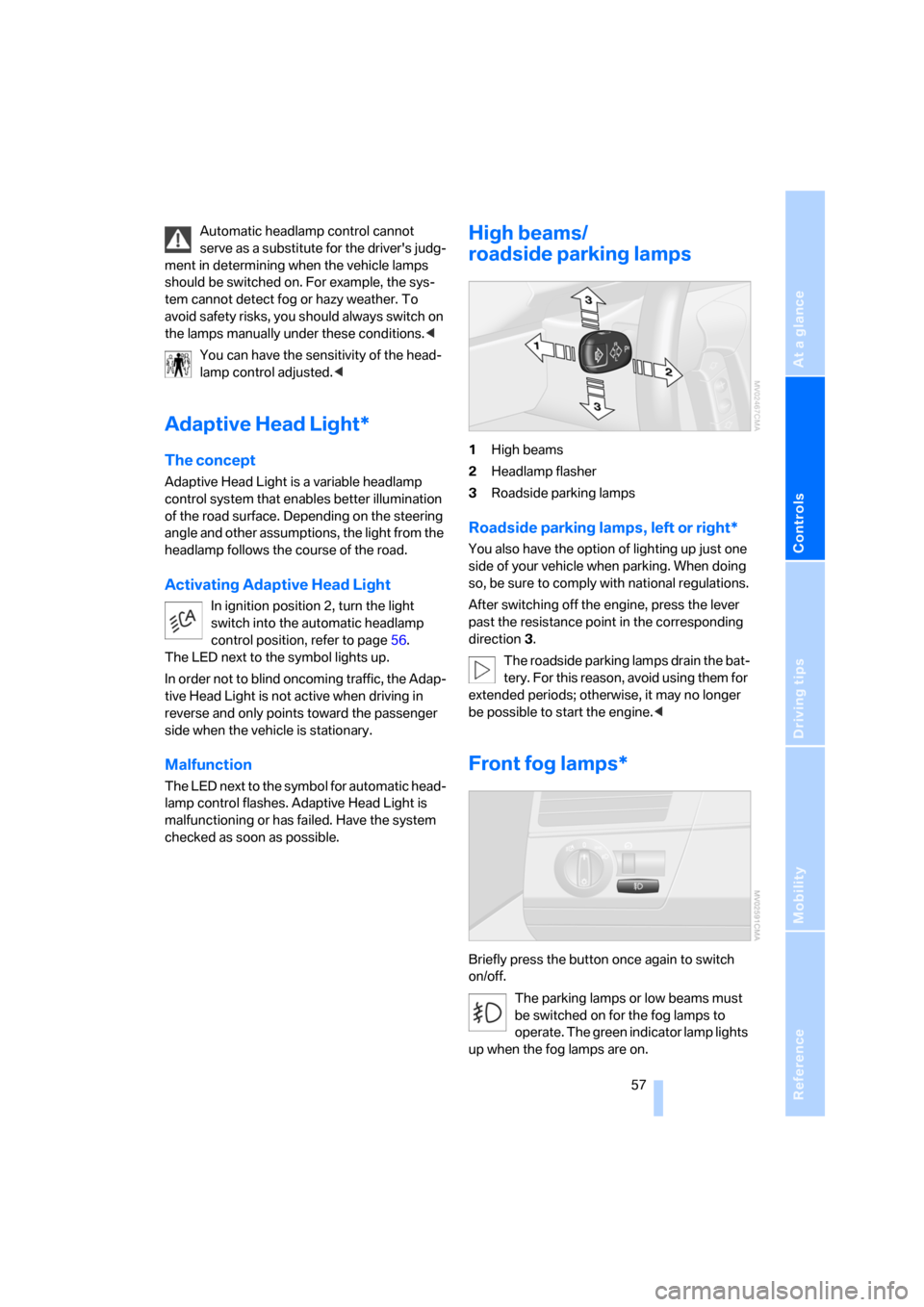
High beams/
roadside parking lamps
1High beams
2Headlamp flasher
3Roadside parking lamps
Roadside parking lamps, left or right*
You also have the option of lighting up just one
side of your vehicle when parking. When doing
so, be sure to comply with national regulations.
After switching off the engine, press the lever
past the resistance point in the corresponding
direction 3.
The roadside parking lamps drain the bat-
tery. For this reason, avoid using them for
extended periods; otherwise, it may no longer
be possible to start the engine.<
Front fog lamps*
Briefly press the button once again to switch
on/off.
The parking lamps or low beams must
be switched on for the fog lamps to
operate. The green indicator lamp lights
up when the fog lamps are on.
Page 62 of 133
Air conditioner
60
Air volume
You can vary the air volume in
steps 1 through 4. The heating or
cooling output is more effective
with a higher air volume.
Switching system on/off
Turn air volume rotary switch to 0. The blower
and air conditioning system are completely
switched off, the air flow is shut off.
To switch on the air conditioning system, set an
arbitrary air volume.
Temperature
To increase the temperature, turn
to the right, toward red.
For a lower temperature, turn the
rotary switch counterclockwise
toward blue.
Air distribution
You can direct air to flow onto the
windows , toward the upper
body and into the footwell .
Intermediate settings are possible.
Rear window defroster
The rear window heating switches
off automatically after a certain
amount of time.
Switching cooling function on/off
When the air conditioning is on, the
air is cooled, dehumidified, and
then reheated depending on the
temperature setting.
Depending on the weather, the windshield may
fog over briefly when the engine is started.
Recirculated-air mode
You can respond to unpleasant
odors outside the vehicle by tem-
porarily suspending the supply of
outside air. The system then recirculates the air
currently within the vehicle.
If condensation starts to form on the
inside window surfaces during operation
in the recirculated-air mode, you should switch
it off and increase the air supply as needed.
The recirculated-air mode should not be used
over a sustained period of time; otherwise, the
air quality inside the vehicle will steadily deteri-
orate.<
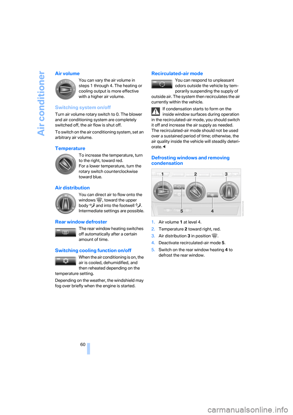
Defrosting windows and removing
condensation
1.Air volume 1 at level 4.
2.Temperature 2 toward right, red.
3.Air distribution 3 in position .
4.Deactivate recirculated-air mode 5.
5.Switch on the rear window heating 4 to
defrost the rear window.
Page 68 of 133
Practical interior accessories
66 The corresponding memory button1 is now
programmed with the signal of the original
hand-held transmitter.
You can use the system when the engine is run-
ning or when the ignition is switched on.
If the system cannot be operated after
repeated programming, check whether
the original hand-held transmitter uses an alter-
nating-code system. To do so, either read the
instructions of the original hand-held transmit-
ter or press and hold down the programmed
memory button 1 of the integrated universal
remote control. If the LED2 on the integrated
universal remote control flashes rapidly for a
short time then lights up for approx. 2 seconds,
this indicates that the original hand-held trans-
mitter uses an alternating-code system. In the
case of an alternating-code system, program
the memory buttons 1 as described in the sec-
tion below on alternating-code transmitters.<
Alternating-code transmitters
Consult the operating instructions of the unit
you wish to set when programming the univer-
sal remote control. You will find information
there on the possibilities for synchronization.
When programming hand-held transmitters
that employ an alternating code, please follow
these additional instructions:
Programming will be easier with the aid of
a second person.<
1.Park your vehicle within the range of the
remote-controlled equipment.
2.Program the integrated universal remote
control as described above in the section on
Fixed-code hand-held transmitters.
3.Locate the button on the receiver of the
equipment to be set, e.g. on its drive unit.
4.Press the button on the receiver of the
device you want to set up. After step 4, you
have approx. 30 seconds for step 5.
5.Press the programmed memory button1
of the integrated universal remote control
three times.The corresponding memory button1 is now
programmed with the signal of the original
hand-held transmitter.
If you have questions, please contact your
BMW Sports Activity Vehicle Center.<
Deleting stored programs
Press both outer buttons1 for approx. 20 sec-
onds, maintaining pressure until the LED2
starts to flash: all stored programs are deleted.
It is not possible to delete individual programs.
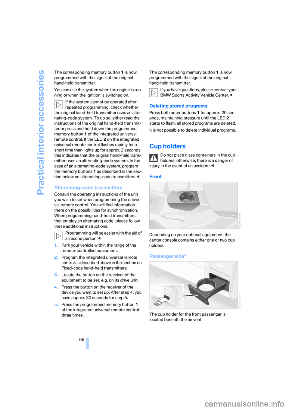
Cup holders
Do not place glass containers in the cup
holders; otherwise, there is a danger of
injury in the event of an accident.<
Front
Depending on your optional equipment, the
center console contains either one or two cup
holders.
Passenger side*
The cup holder for the front passenger is
located beneath the air vent.
Page 80 of 133
Things to remember when driving
78
Safe braking
Your BMW is equipped with ABS as standard
equipment. In situations in which it is required, it
is best to apply the brakes fully. Since the vehi-
cle maintains steering responsiveness, you can
nevertheless avoid possible obstacles with a
minimum of steering effort.
Pulsation at the brake pedal combined with
sounds from the hydraulic circuits indicates to
the driver that ABS is in its active mode.
Wet roads
On wet roads or in heavy rain, briefly apply light
pressure to the brake pedal every few miles.
Watch traffic conditions to ensure that this
maneuver does not endanger other road users.
The heat that is generated by the brake applica-
tions helps to dry the brake pads and rotors.
The full braking force will then be available
when you need it.
Hills
To prevent overheating and reduced effi-
ciency of the brake system, drive long or
steep downhill grades in the gear in which the
least braking is required. Otherwise, even light
but continuous pressure on the brake can lead
to high temperatures, brake wear and possibly
even brake failure.<
The braking action of the engine can be further
intensified by downshifting, all the way down to
first gear if need be. This strategy helps you
avoid placing excessive loads on the brake sys-
tem. Downshifting in manual mode of automatic
transmission, refer to page39. When descend-
ing hills slowly, use HDC Hill Descent Control,
refer to page49.
Never drive with the clutch depressed,
with the transmission in neutral, or with
the engine switched off; otherwise, you will
have neither the braking action of the engine or
nor its power assistance to the brakes or steer-
ing.
Never allow floor mats, carpeting, or other arti-
cles to protrude into the area around the brake
or accelerator pedals and obstruct their move-
ment.<
Corrosion on brake rotors
When the vehicle is driven only occasionally,
during extended periods when the vehicle is not
used at all, and in operating conditions where
brake applications are less frequent, there is an
increased tendency for corrosion to form on
rotors, while contaminants accumulate on the
brake pads. This occurs because the minimal
pressure which must be exerted by the pads
during brake applications to clean the rotors is
not reached.
Should corrosion form on the brake rotors, the
brakes will tend to respond with a pulsating
effect that even extended application will fail to
cure.
Cargo loading
To avoid loading the tires beyond their
approved carrying capacity, never over-
load the vehicle. Overloading can lead to over-
heating and increases the rate at which damage
develops inside the tires. The ultimate result
can assume the form of a sudden blow-out.<
Determining load limit
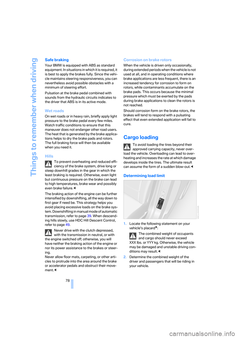
1.Locate the following statement on your
vehicle's placard
*:
The combined weight of occupants
and cargo should never exceed
XXX lbs. or YYY kg. Otherwise, the vehicle
may be damaged and unstable driving con-
ditions may result.<
2.Determine the combined weight of the
driver and passengers that will be riding in
your vehicle.