BMW X3 XDRIVE 28I 2014 Workshop Manual
Manufacturer: BMW, Model Year: 2014, Model line: X3 XDRIVE 28I, Model: BMW X3 XDRIVE 28I 2014Pages: 208, PDF Size: 5.21 MB
Page 51 of 208
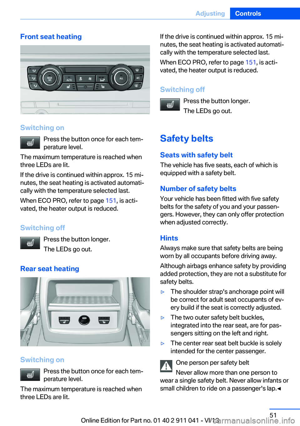
Front seat heating
Switching onPress the button once for each tem‐
perature level.
The maximum temperature is reached when
three LEDs are lit.
If the drive is continued within approx. 15 mi‐
nutes, the seat heating is activated automati‐
cally with the temperature selected last.
When ECO PRO, refer to page 151, is acti‐
vated, the heater output is reduced.
Switching off Press the button longer.
The LEDs go out.
Rear seat heating
Switching on Press the button once for each tem‐
perature level.
The maximum temperature is reached when
three LEDs are lit.
If the drive is continued within approx. 15 mi‐
nutes, the seat heating is activated automati‐
cally with the temperature selected last.
When ECO PRO, refer to page 151, is acti‐
vated, the heater output is reduced.
Switching off Press the button longer.
The LEDs go out.
Safety belts Seats with safety beltThe vehicle has five seats, each of which is
equipped with a safety belt.
Number of safety belts
Your vehicle has been fitted with five safety
belts for the safety of you and your passen‐
gers. However, they can only offer protection
when adjusted correctly.
Hints
Always make sure that safety belts are being
worn by all occupants before driving away.
Although airbags enhance safety by providing
added protection, they are not a substitute for
safety belts.▷The shoulder strap's anchorage point will
be correct for adult seat occupants of ev‐
ery build if the seat is correctly adjusted.▷The two outer safety belt buckles,
integrated into the rear seat, are for pas‐
sengers sitting on the left and right.▷The center rear seat belt buckle is solely
intended for the center passenger.
One person per safety belt
Never allow more than one person to
wear a single safety belt. Never allow infants or
small children to ride on a passenger's lap.◀
Seite 51AdjustingControls51
Online Edition for Part no. 01 40 2 911 041 - VI/13
Page 52 of 208
Putting on the belt
Lay the belt, without twisting, snugly
across the lap and shoulders, as close to the
body as possible. Make sure that the belt lies
low around the hips in the lap area and does
not press on the abdomen. Otherwise, the belt
can slip over the hips in the lap area in a frontal
impact and injure the abdomen.
The safety belt must not lie across the neck,
rub on sharp edges, be routed over solid or
breakable objects, or be pinched.◀
Reduction of restraining effect
Avoid wearing clothing that prevents the
belt from fitting properly, and pull the shoulder
belt periodically to readjust the tension across
your lap; otherwise, the retention effect of the
safety belt may be reduced.◀
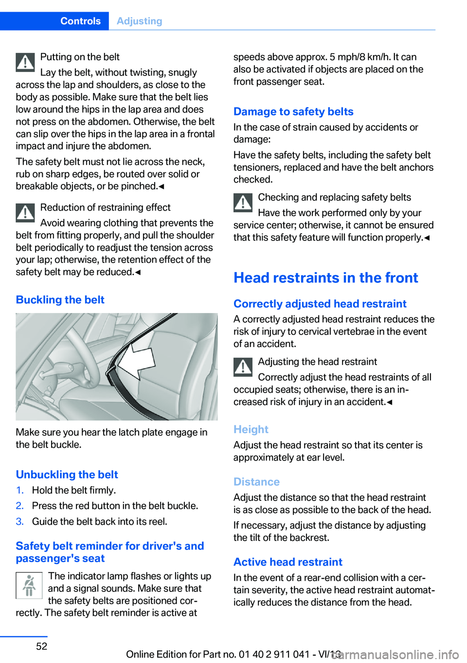
Buckling the belt
Make sure you hear the latch plate engage in
the belt buckle.
Unbuckling the belt
1.Hold the belt firmly.2.Press the red button in the belt buckle.3.Guide the belt back into its reel.
Safety belt reminder for driver's and
passenger's seat
The indicator lamp flashes or lights up
and a signal sounds. Make sure that
the safety belts are positioned cor‐
rectly. The safety belt reminder is active at
speeds above approx. 5 mph/8 km/h. It can
also be activated if objects are placed on the
front passenger seat.
Damage to safety belts In the case of strain caused by accidents or
damage:
Have the safety belts, including the safety belt
tensioners, replaced and have the belt anchors
checked.
Checking and replacing safety belts
Have the work performed only by your
service center; otherwise, it cannot be ensured
that this safety feature will function properly.◀
Head restraints in the front
Correctly adjusted head restraint A correctly adjusted head restraint reduces the
risk of injury to cervical vertebrae in the event
of an accident.
Adjusting the head restraint
Correctly adjust the head restraints of all
occupied seats; otherwise, there is an in‐ creased risk of injury in an accident.◀
Height
Adjust the head restraint so that its center is
approximately at ear level.
Distance Adjust the distance so that the head restraint
is as close as possible to the back of the head.
If necessary, adjust the distance by adjusting
the tilt of the backrest.
Active head restraint In the event of a rear-end collision with a cer‐
tain severity, the active head restraint automat‐
ically reduces the distance from the head.Seite 52ControlsAdjusting52
Online Edition for Part no. 01 40 2 911 041 - VI/13
Page 53 of 208
Reduced protective function▷Do not use seat or head restraint
covers.▷Do not hang objects, e.g., clothes hangers,
on the head restraints.▷Only attach accessories approved by BMW
to the seat or head restraint.
Otherwise, the protective function of the active
head restraint will be impaired and the per‐
sonal safety of the occupants will be endan‐
gered.◀
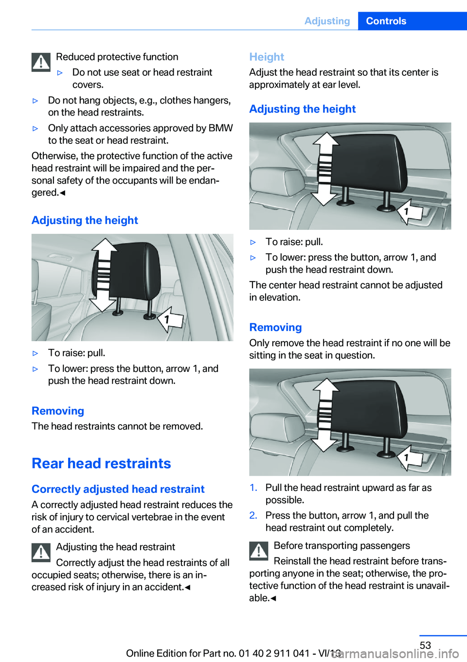
Adjusting the height
▷To raise: pull.▷To lower: press the button, arrow 1, and
push the head restraint down.
Removing
The head restraints cannot be removed.
Rear head restraints
Correctly adjusted head restraint A correctly adjusted head restraint reduces the
risk of injury to cervical vertebrae in the event
of an accident.
Adjusting the head restraint
Correctly adjust the head restraints of all
occupied seats; otherwise, there is an in‐ creased risk of injury in an accident.◀
Height
Adjust the head restraint so that its center is
approximately at ear level.
Adjusting the height▷To raise: pull.▷To lower: press the button, arrow 1, and
push the head restraint down.
The center head restraint cannot be adjusted
in elevation.
RemovingOnly remove the head restraint if no one will be
sitting in the seat in question.
1.Pull the head restraint upward as far as
possible.2.Press the button, arrow 1, and pull the
head restraint out completely.
Before transporting passengers
Reinstall the head restraint before trans‐
porting anyone in the seat; otherwise, the pro‐
tective function of the head restraint is unavail‐
able.◀
Seite 53AdjustingControls53
Online Edition for Part no. 01 40 2 911 041 - VI/13
Page 54 of 208
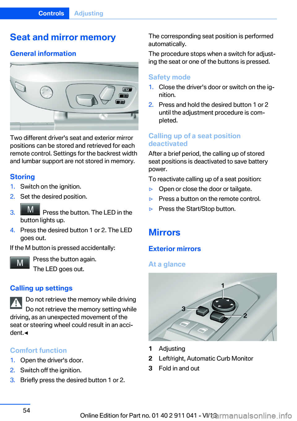
Seat and mirror memory
General information
Two different driver's seat and exterior mirror
positions can be stored and retrieved for each
remote control. Settings for the backrest width
and lumbar support are not stored in memory.
Storing
1.Switch on the ignition.2.Set the desired position.3. Press the button. The LED in the
button lights up.4.Press the desired button 1 or 2. The LED
goes out.
If the M button is pressed accidentally:
Press the button again.
The LED goes out.
Calling up settings Do not retrieve the memory while driving
Do not retrieve the memory setting while
driving, as an unexpected movement of the
seat or steering wheel could result in an acci‐
dent.◀
Comfort function
1.Open the driver's door.2.Switch off the ignition.3.Briefly press the desired button 1 or 2.The corresponding seat position is performed
automatically.
The procedure stops when a switch for adjust‐
ing the seat or one of the buttons is pressed.
Safety mode1.Close the driver's door or switch on the ig‐
nition.2.Press and hold the desired button 1 or 2
until the adjustment procedure is com‐
pleted.
Calling up of a seat position
deactivated
After a brief period, the calling up of stored
seat positions is deactivated to save battery
power.
To reactivate calling up of a seat position:
▷Open or close the door or tailgate.▷Press a button on the remote control.▷Press the Start/Stop button.
Mirrors
Exterior mirrors
At a glance
1Adjusting2Left/right, Automatic Curb Monitor3Fold in and outSeite 54ControlsAdjusting54
Online Edition for Part no. 01 40 2 911 041 - VI/13
Page 55 of 208
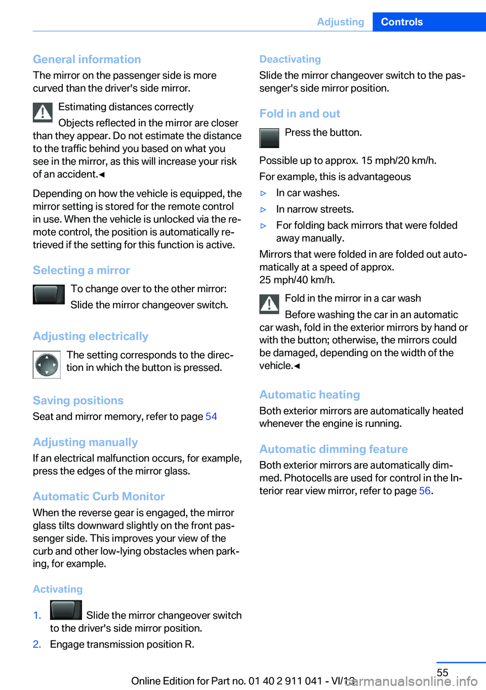
General information
The mirror on the passenger side is more
curved than the driver's side mirror.
Estimating distances correctly
Objects reflected in the mirror are closer
than they appear. Do not estimate the distance
to the traffic behind you based on what you
see in the mirror, as this will increase your risk
of an accident.◀
Depending on how the vehicle is equipped, the
mirror setting is stored for the remote control
in use. When the vehicle is unlocked via the re‐
mote control, the position is automatically re‐
trieved if the setting for this function is active.
Selecting a mirror To change over to the other mirror:Slide the mirror changeover switch.
Adjusting electrically The setting corresponds to the direc‐
tion in which the button is pressed.
Saving positions Seat and mirror memory, refer to page 54
Adjusting manually If an electrical malfunction occurs, for example,
press the edges of the mirror glass.
Automatic Curb Monitor When the reverse gear is engaged, the mirror
glass tilts downward slightly on the front pas‐
senger side. This improves your view of the
curb and other low-lying obstacles when park‐
ing, for example.
Activating1. Slide the mirror changeover switch
to the driver's side mirror position.2.Engage transmission position R.Deactivating
Slide the mirror changeover switch to the pas‐
senger's side mirror position.
Fold in and out Press the button.
Possible up to approx. 15 mph/20 km/h.
For example, this is advantageous▷In car washes.▷In narrow streets.▷For folding back mirrors that were folded
away manually.
Mirrors that were folded in are folded out auto‐
matically at a speed of approx.
25 mph/40 km/h.
Fold in the mirror in a car wash
Before washing the car in an automatic
car wash, fold in the exterior mirrors by hand or
with the button; otherwise, the mirrors could
be damaged, depending on the width of the
vehicle.◀
Automatic heating
Both exterior mirrors are automatically heated
whenever the engine is running.
Automatic dimming feature Both exterior mirrors are automatically dim‐
med. Photocells are used for control in the In‐
terior rear view mirror, refer to page 56.
Seite 55AdjustingControls55
Online Edition for Part no. 01 40 2 911 041 - VI/13
Page 56 of 208
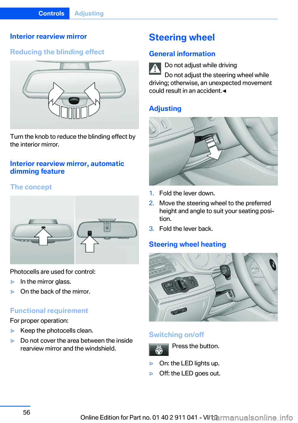
Interior rearview mirror
Reducing the blinding effect
Turn the knob to reduce the blinding effect by
the interior mirror.
Interior rearview mirror, automaticdimming feature
The concept
Photocells are used for control:
▷In the mirror glass.▷On the back of the mirror.
Functional requirement For proper operation:
▷Keep the photocells clean.▷Do not cover the area between the inside
rearview mirror and the windshield.Steering wheel
General information Do not adjust while driving
Do not adjust the steering wheel while
driving; otherwise, an unexpected movement
could result in an accident.◀
Adjusting1.Fold the lever down.2.Move the steering wheel to the preferred
height and angle to suit your seating posi‐
tion.3.Fold the lever back.
Steering wheel heating
Switching on/off
Press the button.
▷On: the LED lights up.▷Off: the LED goes out.Seite 56ControlsAdjusting56
Online Edition for Part no. 01 40 2 911 041 - VI/13
Page 57 of 208
Transporting children safelyVehicle equipmentAll standard, country-specific and optional
equipment that is offered in the model series is
described in this chapter. Therefore, equip‐
ment is also described that is not available in a
vehicle, e. g., because of the selected optional
equipment or country variant. This also applies
for safety-related functions and systems.
The right place for children Note Children in the vehicle
Do not leave children unattended in the
vehicle; otherwise, they could endanger them‐
selves and other persons, e.g., by opening the
doors.◀
Children should always be in the rear
Accident research shows that the safest place
for children is in the back seat.
Transporting children in the rear
Only transport children younger than
13 years of age or shorter than 5 ft/150 cm in
the rear in child restraint fixing systems pro‐
vided in accordance with the age, weight and
size of the child; otherwise, there is an in‐
creased risk of injury in an accident.
Children 13 years of age or older must wear a
safety belt as soon as a suitable child restraint
fixing system can no longer be used, due to
their age, weight and size.◀
Children on the front passenger seat
Should it ever be necessary to use a child re‐
straint fixing system in the front passenger
seat, make sure that the front, knee and side
airbags on the front passenger side are deacti‐vated. Automatic deactivation of front passen‐
ger side airbags, refer to page 96.
Note Deactivated front passenger airbags
If a child restraint fixing system is used in
the front passenger seat, the front passenger
airbags must be deactivated; otherwise, there
is an increased risk of injury to the child when
the airbags are triggered, even with a child re‐
straint fixing system.◀
Installing child restraint
fixing systems
Before mounting
Before mounting child restraint fixing systems,
ensure that the rear seat backrests are locked.
Hints Manufacturer's information for child re‐
straint fixing systems
To select, mount and use child restraint fixing
systems, observe the information provided by
the system manufacturer; otherwise, the pro‐
tective effect can be impaired.◀
Lock the rear seat backrests in position
Before installing a child restraint system,
make sure that the rear seat backrests are
locked; otherwise, the protective effect is not
guaranteed and there is an increased risk of in‐
jury for the child in the event of an accident.◀
On the front passenger seat
Deactivating airbags
After installing a child restraint fixing system in
the front passenger seat, make sure that theSeite 57Transporting children safelyControls57
Online Edition for Part no. 01 40 2 911 041 - VI/13
Page 58 of 208
front, knee and side airbags on the front pas‐
senger side are deactivated.
Deactivate the front passenger airbags auto‐
matically, refer to page 96.
Deactivating the front passenger airbags
If a child restraint fixing system is used in
the front passenger seat, the front passenger
airbags must be deactivated; otherwise, there
is an increased risk of injury to the child when
the airbags are triggered, even with a child re‐
straint fixing system.◀
Seat position and height
Before installing a child restraint fixing system,
move the front passenger seat as far back as
possible and adjust its height to the highest
position to obtain the best possible position for
the belt and to offer optimal protection in the
event of an accident.
Do not change the seat position and height af‐
ter this.
Backrest width Adjustable backrest width: before installing a
child restraint fixing system in the front pas‐
senger seat, open the backrest width com‐
pletely. Do not change the backrest width
again and do not call up a memory position.
Backrest width for the child seat
Before installing a child restraint fixing
system in the front passenger seat, the back‐
rest width must be opened completely. Do not
change the adjustment after this; otherwise,
the stability of the child seat will be reduced.◀Child seat security
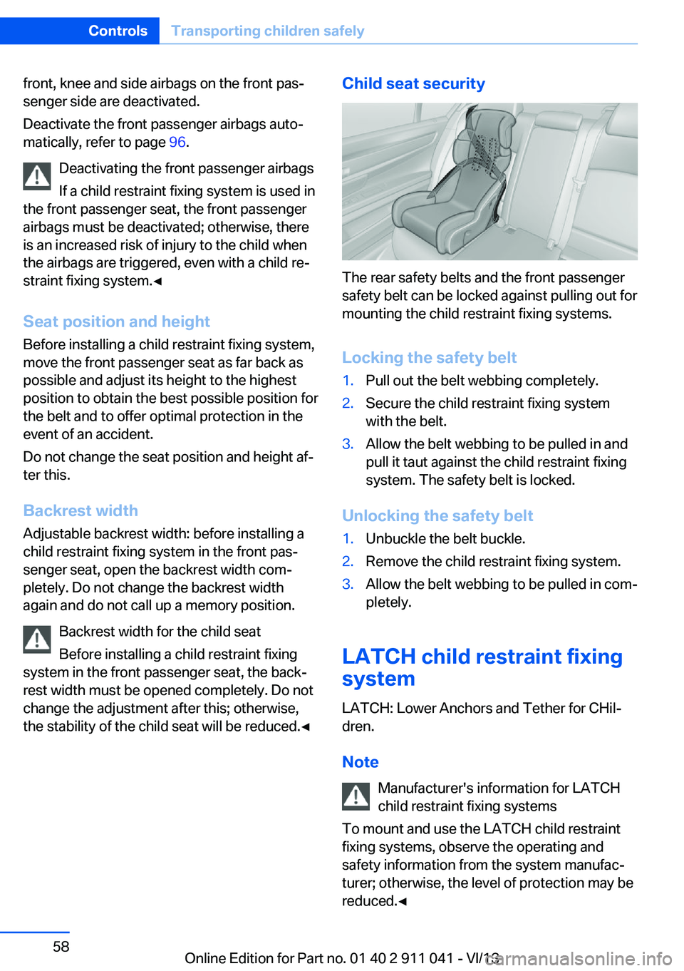
The rear safety belts and the front passenger
safety belt can be locked against pulling out for
mounting the child restraint fixing systems.
Locking the safety belt
1.Pull out the belt webbing completely.2.Secure the child restraint fixing system
with the belt.3.Allow the belt webbing to be pulled in and
pull it taut against the child restraint fixing
system. The safety belt is locked.
Unlocking the safety belt
1.Unbuckle the belt buckle.2.Remove the child restraint fixing system.3.Allow the belt webbing to be pulled in com‐
pletely.
LATCH child restraint fixing
system
LATCH: Lower Anchors and Tether for CHil‐dren.
Note Manufacturer's information for LATCH
child restraint fixing systems
To mount and use the LATCH child restraint
fixing systems, observe the operating and
safety information from the system manufac‐
turer; otherwise, the level of protection may be
reduced.◀
Seite 58ControlsTransporting children safely58
Online Edition for Part no. 01 40 2 911 041 - VI/13
Page 59 of 208
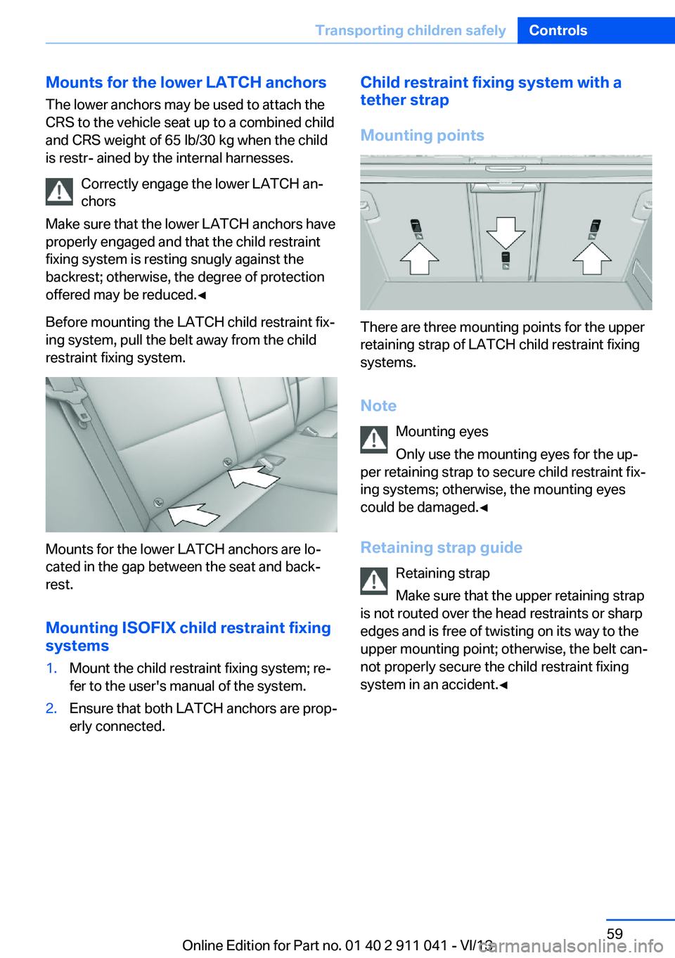
Mounts for the lower LATCH anchorsThe lower anchors may be used to attach the
CRS to the vehicle seat up to a combined child
and CRS weight of 65 lb/30 kg when the child
is restr- ained by the internal harnesses.
Correctly engage the lower LATCH an‐
chors
Make sure that the lower LATCH anchors have
properly engaged and that the child restraint
fixing system is resting snugly against the
backrest; otherwise, the degree of protection
offered may be reduced.◀
Before mounting the LATCH child restraint fix‐
ing system, pull the belt away from the child
restraint fixing system.
Mounts for the lower LATCH anchors are lo‐
cated in the gap between the seat and back‐
rest.
Mounting ISOFIX child restraint fixing systems
1.Mount the child restraint fixing system; re‐
fer to the user's manual of the system.2.Ensure that both LATCH anchors are prop‐
erly connected.Child restraint fixing system with a
tether strap
Mounting points
There are three mounting points for the upper
retaining strap of LATCH child restraint fixing
systems.
Note Mounting eyes
Only use the mounting eyes for the up‐
per retaining strap to secure child restraint fix‐
ing systems; otherwise, the mounting eyes
could be damaged.◀
Retaining strap guide Retaining strap
Make sure that the upper retaining strap
is not routed over the head restraints or sharp
edges and is free of twisting on its way to the
upper mounting point; otherwise, the belt can‐
not properly secure the child restraint fixing
system in an accident.◀
Seite 59Transporting children safelyControls59
Online Edition for Part no. 01 40 2 911 041 - VI/13
Page 60 of 208
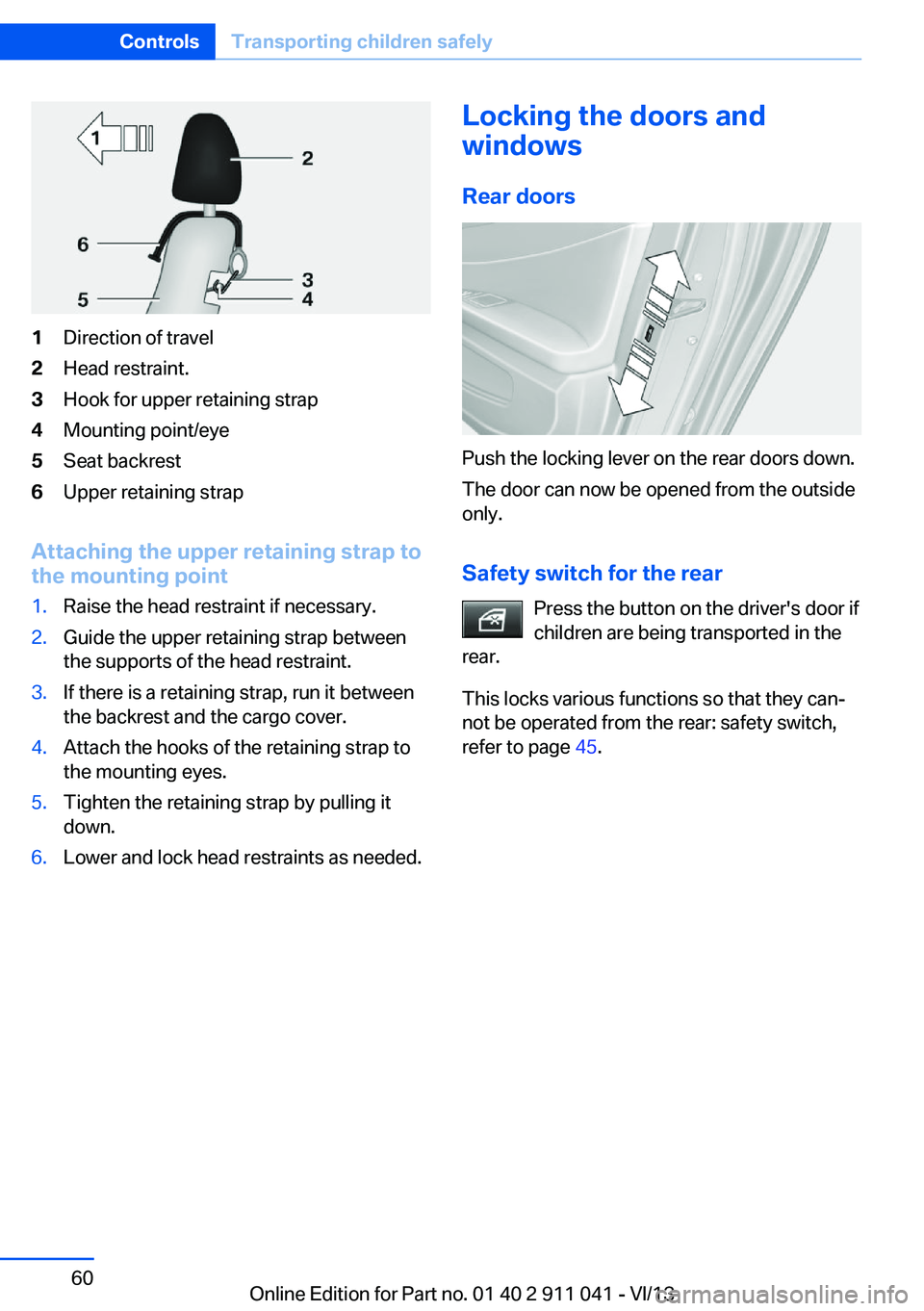
1Direction of travel2Head restraint.3Hook for upper retaining strap4Mounting point/eye5Seat backrest6Upper retaining strap
Attaching the upper retaining strap to
the mounting point
1.Raise the head restraint if necessary.2.Guide the upper retaining strap between
the supports of the head restraint.3.If there is a retaining strap, run it between
the backrest and the cargo cover.4.Attach the hooks of the retaining strap to
the mounting eyes.5.Tighten the retaining strap by pulling it
down.6.Lower and lock head restraints as needed.Locking the doors and
windows
Rear doors
Push the locking lever on the rear doors down.
The door can now be opened from the outside
only.
Safety switch for the rear Press the button on the driver's door if
children are being transported in the
rear.
This locks various functions so that they can‐
not be operated from the rear: safety switch,
refer to page 45.
Seite 60ControlsTransporting children safely60
Online Edition for Part no. 01 40 2 911 041 - VI/13