rear entertainment BMW X3 XDRIVE 35I 2011 User Guide
[x] Cancel search | Manufacturer: BMW, Model Year: 2011, Model line: X3 XDRIVE 35I, Model: BMW X3 XDRIVE 35I 2011Pages: 262, PDF Size: 11.2 MB
Page 79 of 262
▷When the windshield in front of the interior
rearview mirror is fogged over, dirty or cov‐
ered with stickers, etc.
Camera
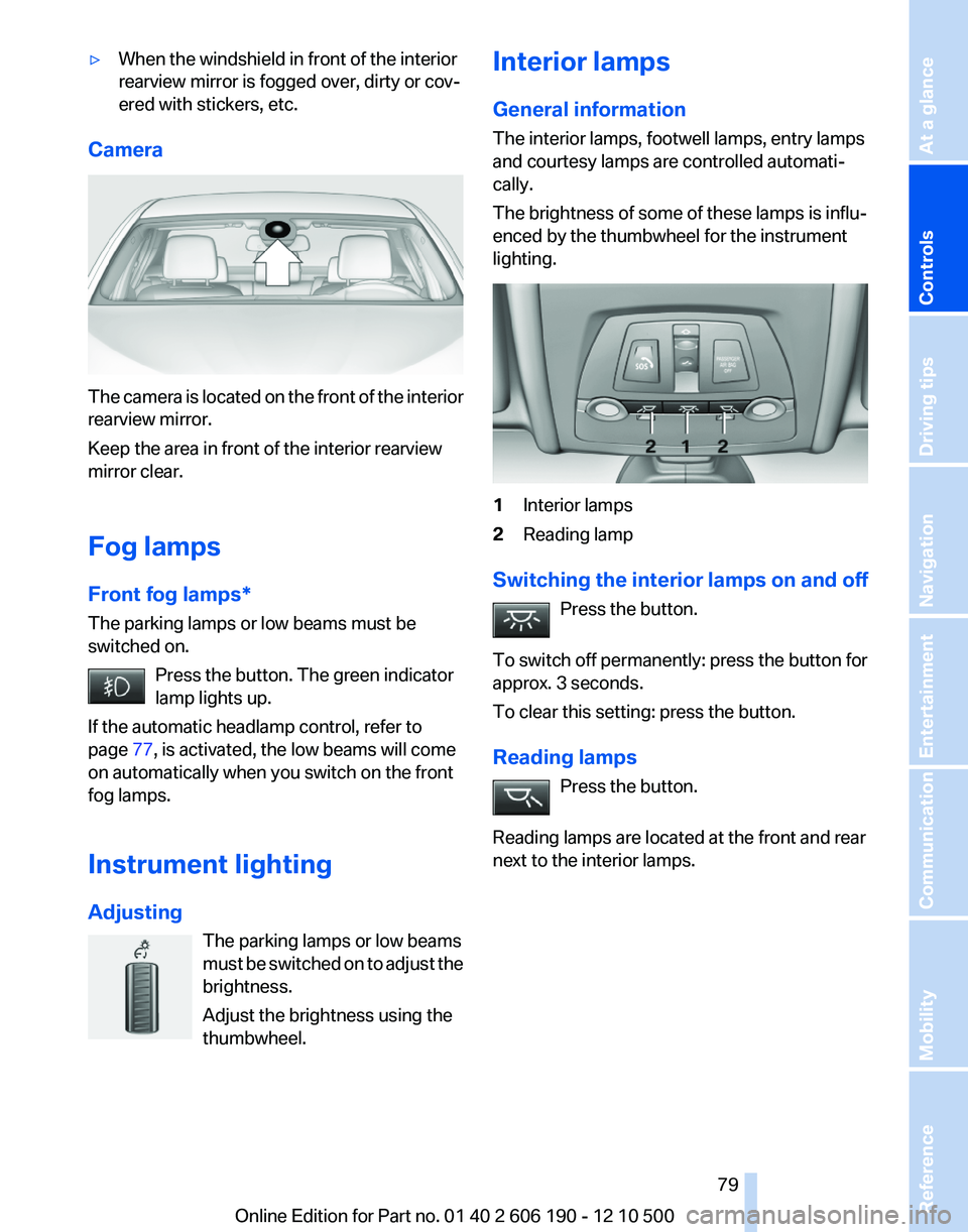
The camera is located on the front of the interior
rearview mirror.
Keep the area in front of the interior rearview
mirror clear.
Fog lamps
Front fog lamps*
The parking lamps or low beams must be
switched on.
Press the button. The green indicator
lamp lights up.
If the automatic headlamp control, refer to
page 77, is activated, the low beams will come
on automatically when you switch on the front
fog lamps.
Instrument lighting
Adjusting The parking lamps or low beams
must be switched on to adjust the
brightness.
Adjust the brightness using the
thumbwheel.
Interior lamps
General information
The interior lamps, footwell lamps, entry lamps
and courtesy lamps are controlled automati‐
cally.
The brightness of some of these lamps is influ‐
enced by the thumbwheel for the instrument
lighting.1Interior lamps2Reading lamp
Switching the interior lamps on and off
Press the button.
To switch off permanently: press the button for
approx. 3 seconds.
To clear this setting: press the button.
Reading lamps Press the button.
Reading lamps are located at the front and rear
next to the interior lamps.
Seite 7979
Online Edition for Part no. 01 40 2 606 190 - 12 10 500
ReferenceMobilityCommunicationEntertainmentNavigationDriving tipsControlsAt a glance
Page 81 of 262
▷Keep the dashboard and window on the
front passenger side clear, i.e., do not cover
with adhesive labels or coverings, and do not
attach holders such as for navigation instru‐
ments and mobile phones.▷Make sure that the front passenger is sitting
correctly, i.e., keeps his or her feet and legs
in the footwell; otherwise, leg injuries can
occur if the front airbag is triggered.▷Do not place slip covers, seat cushions or
other objects on the front passenger seat
that are not approved specifically for seats
with integrated side airbags.▷Do not hang pieces of clothing, such as jack‐
ets, over the backrests.▷Make sure that occupants keep their heads
away from the side airbag and do not rest
against the head airbag; otherwise, injuries
can occur if the airbags are triggered.▷Do not remove the airbag restraint system.▷Do not remove the steering wheel.▷Do not apply adhesive materials to the air‐
bag cover panels, cover them or modify
them in any way.▷Never modify either the individual compo‐
nents or the wiring in the airbag system. This
also applies to steering wheel covers, the
dashboard, the seats, the roof pillars and the
sides of the headliner.◀
Even when all instructions are followed closely,
injury from contact with the airbags cannot be
ruled out in certain situations.
The ignition and inflation noise may lead to
short-term and, in most cases, temporary hear‐
ing impairment in sensitive individuals.
In the case of a malfunction, deactivation
and after triggering of the airbags
Do not touch the individual components imme‐
diately after the system has been triggered; oth‐
erwise, there is the danger of burns.
Only have the airbags checked, repaired or dis‐
mantled and the airbag generator scrapped by
your service center or a workshop that has the
necessary authorization for handling explosives.
Non-professional attempts to service the sys‐
tem could lead to failure in an emergency or un‐
desired triggering of the airbag, either of which
could result in injury.◀
Warnings and information on the airbags are
also found on the sun visors.
Automatic deactivation of the front
passenger airbags
The system determines whether the front pas‐
senger seat is occupied by measuring the re‐
sistance of the human body.
The front, knee, and side airbag on the front
passenger side are activated or deactivated ac‐
cordingly.
Leave feet in the footwell
Make sure that the front passenger keeps
his or her feet in the footwell; otherwise, the front
passenger airbags may not function properly.◀
Child restraint fixing system in the front
passenger seat
Before transporting a child on the front passen‐
ger seat, see the safety notes and instructions
under Children on the front passenger seat.◀
Malfunction of the automatic
deactivation system
When transporting older children and adults, the
front passenger airbags may be deactivated in
certain sitting positions. In this case, the indica‐
tor lamp for the front passenger airbags lights
up.
In this case, change the sitting position so that
the front passenger airbags are activated and
the indicator lamp goes out.
If it is not possible to activate the airbags, have
the person sit in the rear.
To make sure that the occupied seat cushion
can be evaluated correctly▷Do not attach covers, cushions, ball mats or
other items to the front passenger seat un‐
less they are specifically recommended by
the manufacturer of your vehicle.Seite 8181
Online Edition for Part no. 01 40 2 606 190 - 12 10 500
ReferenceMobilityCommunicationEntertainmentNavigationDriving tipsControlsAt a glance
Page 87 of 262
The system ensures maximum forward momen‐
tum on special road conditions, e.g., unplowed
snowy roads, but driving stability is limited.
It is therefore necessary to drive with appropri‐
ate caution.
You may find it useful to briefly activate DTC un‐
der the following special circumstances:▷When driving in slush or on uncleared,
snow-covered roads.▷When rocking the vehicle or driving off in
deep snow or on loose surfaces.▷When driving with snow chains.
Deactivating/activating DTC Dynamic
Traction Control
Activating the Dynamic Traction Control DTC
provides maximum traction on loose ground.
Driving stability is limited during acceleration
and when driving in bends.
Activating DTC Press the button.
TRACTION is displayed in the instru‐
ment cluster and the indicator lamp for DSC
lights up.
Deactivating DTC Press the button again.
TRACTION and the DSC indicator lamp
go out.
Performance Control*
Performance Control enhances the agility of
your vehicle.
To enhance performance during sporty driving,
the rear wheel on the inside of the curve is
braked while the resulting braking effect is
largely compensated by engine intervention.
xDrive
xDrive is the all-wheel-drive system of your ve‐
hicle. Concerted action by the xDrive and DSC
further optimize traction and driving dynamics.
The xDrive all-wheel-drive system variably dis‐
tributes the drive forces to the front and rear
axles as demanded by the driving situation and
road surface.
HDC Hill Descent Control
The concept
HDC is a downhill driving assistant that auto‐
matically controls vehicle speed on steep down‐
hill gradients. Without requiring brake applica‐
tion, the vehicle moves at slightly more than
twice walking speed.
You can activate the Hill Descent Control at
speeds below approx. 22 mph/35 km/h. When
driving downhill, the vehicle reduces its speed
to approx. twice walking speed and then keeps
its speed constant.
While you are actively braking, the system is on
standby. The system does not brake the vehicle
during this time.
Use HDC in low gears or in transmission position
D or R only.
Changing the speed
The speed can be changed in the range from
roughly twice walking speed to approx. 15 mph/
25 km/h by lightly pressing the accelerator.
To set the speed: buttons* on the
steering wheel
The desired speed can be specified in the range
from roughly twice walking speed to approx.
15 mph/25 km/h using the rocker switch of the
cruise control on the steering wheel.Seite 8787
Online Edition for Part no. 01 40 2 606 190 - 12 10 500
ReferenceMobilityCommunicationEntertainmentNavigationDriving tipsControlsAt a glance
Page 93 of 262
Brief status display
Brief display in the speedometer:
Selected desired speed
If --- appears briefly, conditions may not be ad‐
equate to operate the system.
PDC Park Distance Control*
The concept
In addition to the PDC Park Distance Control, the
backup camera*, refer to page 95, can be
switched on.
PDC supports you when parking. Objects that
you are approaching slowly in front of or behind
your vehicle are indicated with:▷Signal tones.▷Visual display.
Measurement
Measurements are made by ultrasound sensors
in the bumpers.
The range is approx. 6 ft/2 m.
An acoustic warning is first given:
▷By the front sensors and two rear corner
sensors at approx. 24 in/60 cm.▷By the rear middle sensors at approx. 5 ft/
1.50 m.
System limits
Check the traffic situation as well
PDC cannot serve as a substitute for the
driver's personal judgment of the traffic situa‐
tion. Check the traffic situation around the vehi‐
cle with your own eyes. Otherwise, an accident
could result from road users or objects located
outside of the PDC detection range.
Loud noises from outside and inside the vehicle
may prevent you from hearing the PDC's signal
tone.◀
Avoid driving quickly with PDC
Avoid approaching an object quickly.
Avoid driving away quickly while PDC is not yet
active.
For technical reasons, the system may other‐
wise be too late in issuing a warning.◀
Limits of ultrasonic measurement
The detection of objects can reach the physical
limits of ultrasonic measurement, for instance:▷With tow bars and trailer hitches.▷With thin or wedge-shaped objects.▷With low objects.▷With objects with corners and sharp edges.
Low objects already displayed, e.g., curbs, can
move into the blind area of the sensors before or
after a continuous tone sounds.
High, protruding objects such as ledges may not
be detected.
False warnings
PDC may issue a warning under the following
conditions even though there is no obstacle
within the detection range:
▷In heavy rain.▷When sensors are very dirty or covered in
ice.▷When sensors are covered in snow.▷On rough road surfaces.▷In large buildings with right angles and
smooth walls, e.g., in underground garages.▷In heavy exhaust.▷Due to other ultrasound sources, e.g.,
sweeping machines, high pressure steam
cleaners or neon lights.
Switching on automatically
Select transmission position R with the engine
running.
Switching off automatically
The system switches off and the LED goes out:
Seite 9393
Online Edition for Part no. 01 40 2 606 190 - 12 10 500
ReferenceMobilityCommunicationEntertainmentNavigationDriving tipsControlsAt a glance
Page 95 of 262
Display on the Control Display
Switching on the backup camera via
iDrive
With PDC activated:
"Rear view camera"
The backup camera image is displayed. The set‐
ting is stored for the remote control currently in
use.
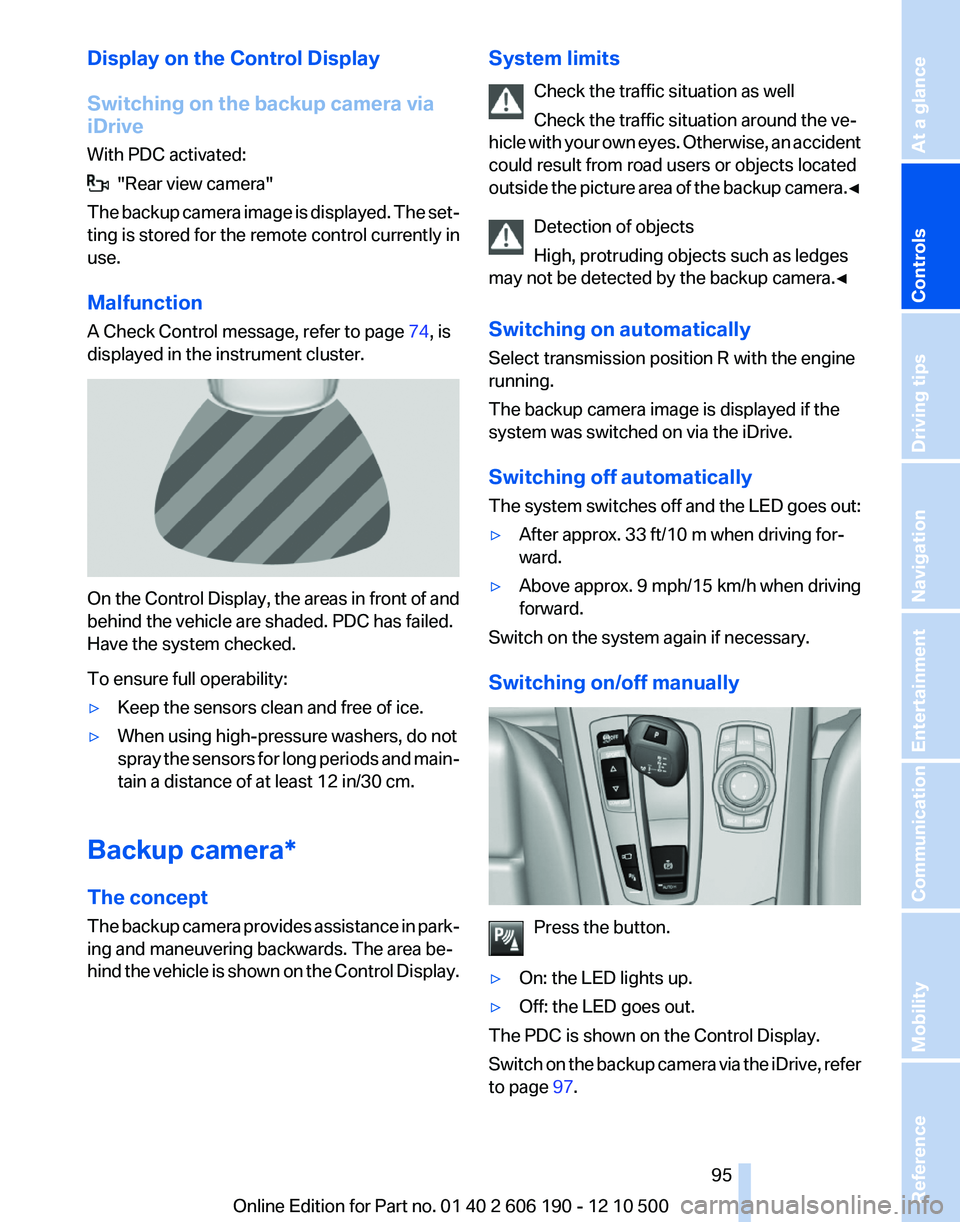
Malfunction
A Check Control message, refer to page 74, is
displayed in the instrument cluster.
On the Control Display, the areas in front of and
behind the vehicle are shaded. PDC has failed.
Have the system checked.
To ensure full operability:
▷Keep the sensors clean and free of ice.▷When using high-pressure washers, do not
spray the sensors for long periods and main‐
tain a distance of at least 12 in/30 cm.
Backup camera*
The concept
The backup camera provides assistance in park‐
ing and maneuvering backwards. The area be‐
hind the vehicle is shown on the Control Display.
System limits
Check the traffic situation as well
Check the traffic situation around the ve‐
hicle with your own eyes. Otherwise, an accident
could result from road users or objects located
outside the picture area of the backup camera. ◀
Detection of objects
High, protruding objects such as ledges
may not be detected by the backup camera.◀
Switching on automatically
Select transmission position R with the engine
running.
The backup camera image is displayed if the
system was switched on via the iDrive.
Switching off automatically
The system switches off and the LED goes out:▷After approx. 33 ft/10 m when driving for‐
ward.▷Above approx. 9 mph/15 km/h when driving
forward.
Switch on the system again if necessary.
Switching on/off manually
Press the button.
▷On: the LED lights up.▷Off: the LED goes out.
The PDC is shown on the Control Display.
Switch on the backup camera via the iDrive, refer
to page 97.
Seite 9595
Online Edition for Part no. 01 40 2 606 190 - 12 10 500
ReferenceMobilityCommunicationEntertainmentNavigationDriving tipsControlsAt a glance
Page 97 of 262
Activating the assistance functions
More than one assistance function can be active
at the same time.
Showing the parking aid lines
"Parking aid lines"
Pathway and turning circle lines are displayed.
Showing the obstacle marking
"Obstacle marking"
Spatially-shaped markings are displayed.
Display on the Control Display
Switching on the backup camera via
iDrive
With PDC activated:
"Rear view camera"
The backup camera image is displayed. The set‐
ting is stored for the remote control currently in
use.
Brightness
With the backup camera switched on:
1. Select the symbol.2.Turn the controller until the desired setting
is reached and press the controller.
Contrast
With the backup camera switched on:
1. Select the symbol.2.Turn the controller until the desired setting
is reached and press the controller.Camera
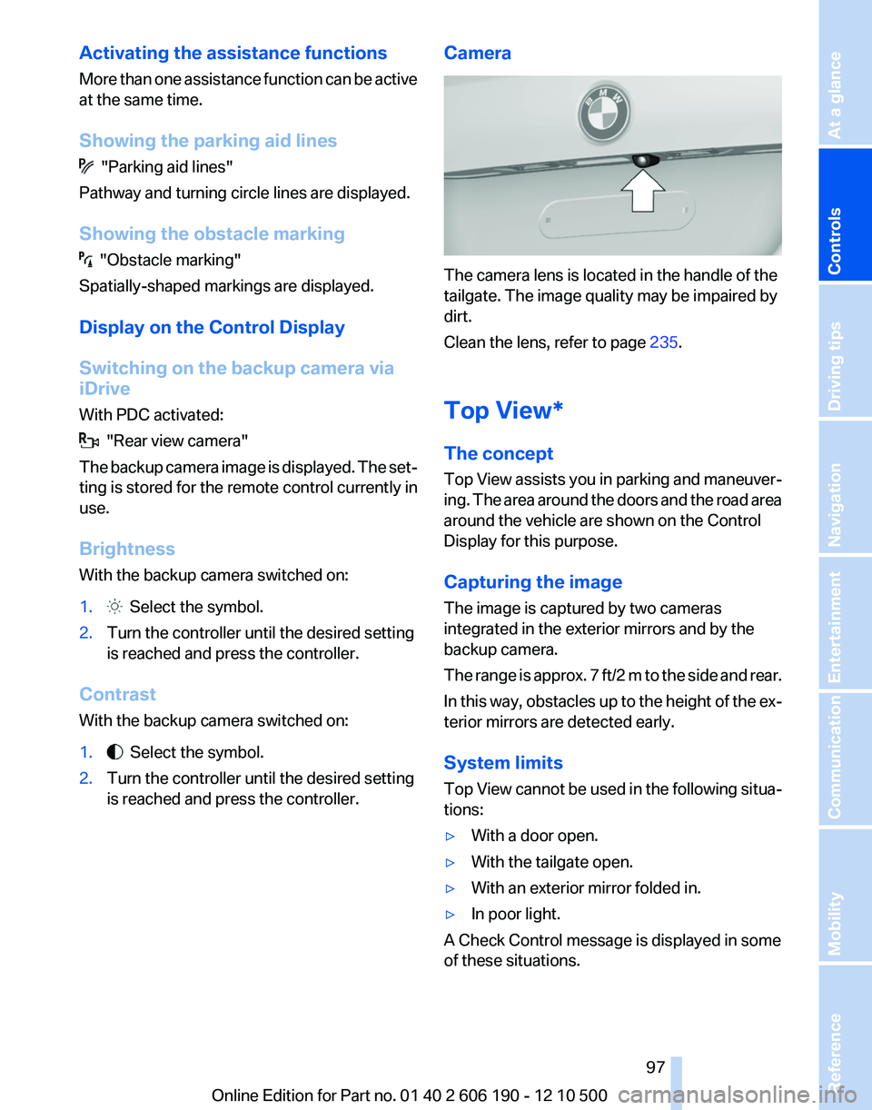
The camera lens is located in the handle of the
tailgate. The image quality may be impaired by
dirt.
Clean the lens, refer to page 235.
Top View*
The concept
Top View assists you in parking and maneuver‐
ing. The area around the doors and the road area
around the vehicle are shown on the Control
Display for this purpose.
Capturing the image
The image is captured by two cameras
integrated in the exterior mirrors and by the
backup camera.
The range is approx. 7 ft/2 m to the side and rear.
In this way, obstacles up to the height of the ex‐
terior mirrors are detected early.
System limits
Top View cannot be used in the following situa‐
tions:
▷With a door open.▷With the tailgate open.▷With an exterior mirror folded in.▷In poor light.
A Check Control message is displayed in some
of these situations.
Seite 9797
Online Edition for Part no. 01 40 2 606 190 - 12 10 500
ReferenceMobilityCommunicationEntertainmentNavigationDriving tipsControlsAt a glance
Page 101 of 262
Climate control
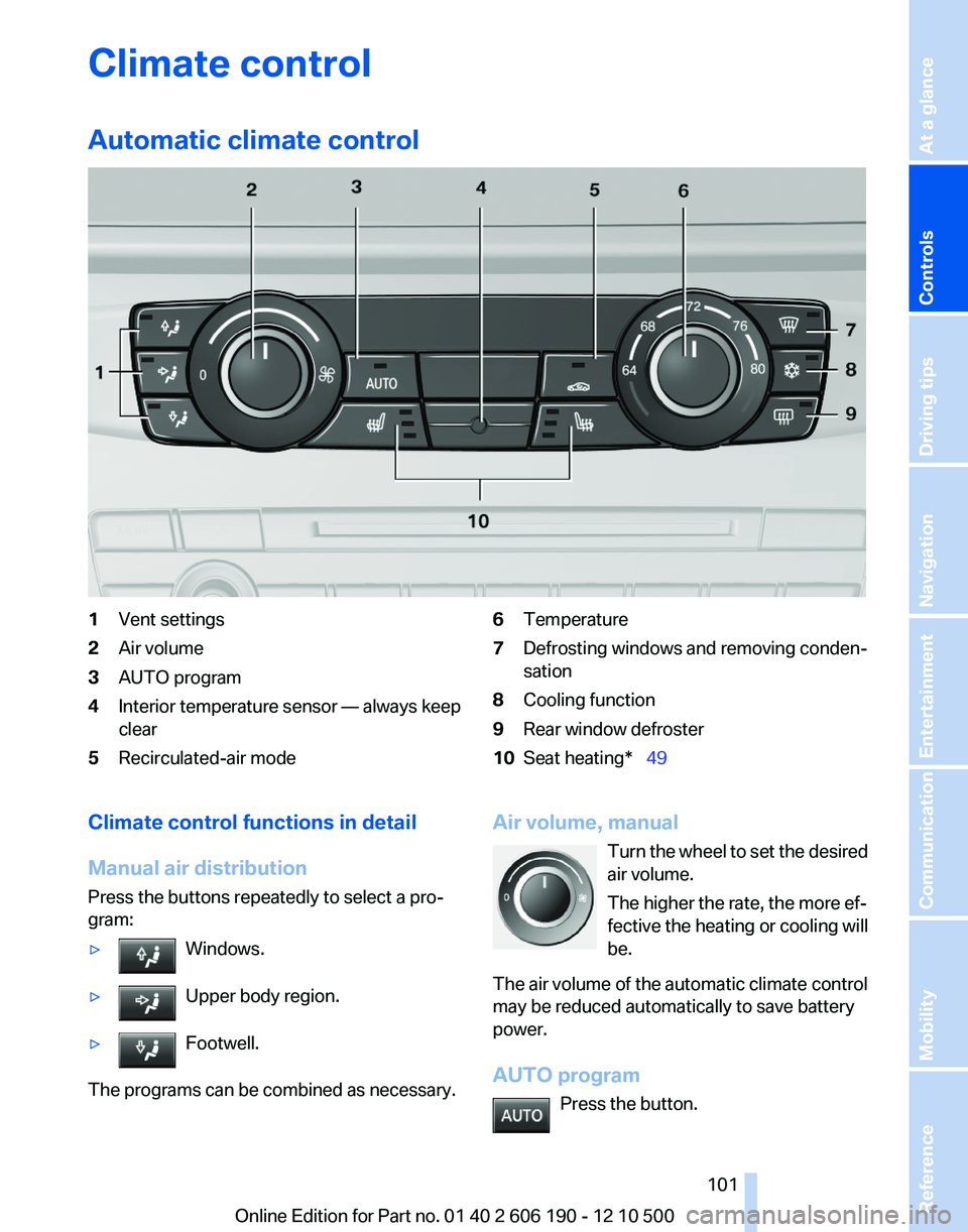
Automatic climate control1Vent settings2Air volume3AUTO program4Interior temperature sensor — always keep
clear5Recirculated-air mode6Temperature7Defrosting windows and removing conden‐
sation8Cooling function9Rear window defroster10Seat heating* 49Climate control functions in detail
Manual air distribution
Press the buttons repeatedly to select a pro‐
gram:▷Windows.▷Upper body region.▷Footwell.
The programs can be combined as necessary.
Air volume, manual
Turn the wheel to set the desired
air volume.
The higher the rate, the more ef‐
fective the heating or cooling will
be.
The air volume of the automatic climate control
may be reduced automatically to save battery
power.
AUTO program Press the button.Seite 101101
Online Edition for Part no. 01 40 2 606 190 - 12 10 500
ReferenceMobilityCommunicationEntertainmentNavigationDriving tipsControlsAt a glance
Page 103 of 262
Microfilter
The microfilter removes dust and pollen from
the incoming air.
This filter should be replaced during scheduled
maintenance of your vehicle.More information can be found in the service re‐
quirements display, refer to page 73.
Automatic climate control with enhanced features*
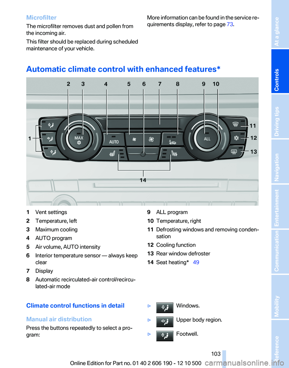
1Vent settings2Temperature, left3Maximum cooling4AUTO program5Air volume, AUTO intensity6Interior temperature sensor — always keep
clear7Display8Automatic recirculated-air control/recircu‐
lated-air mode9ALL program10Temperature, right11Defrosting windows and removing conden‐
sation12Cooling function13Rear window defroster14Seat heating* 49Climate control functions in detail
Manual air distribution
Press the buttons repeatedly to select a pro‐
gram:▷Windows.▷Upper body region.▷Footwell.Seite 103103
Online Edition for Part no. 01 40 2 606 190 - 12 10 500
ReferenceMobilityCommunicationEntertainmentNavigationDriving tipsControlsAt a glance
Page 105 of 262
If the windows are fogged over, switch off
the recirculated-air mode and press the
AUTO button to utilize the condensation
sensor. Make sure that air can flow onto the
windshield.
Continuous recirculated-air mode
The recirculated-air mode should not be
used for an extended period of time, as the air
quality inside the vehicle deteriorates steadily. ◀
ALL program Press the button.
The current setting or later settings of
the temperature on the driver's side are trans‐
ferred to the front passenger side.
The program is switched off if the settings on
the front passenger side are changed.
Defrosting windows and removing
condensation
Press the button.
Ice and condensation are quickly re‐
moved from the windshield and the front side
windows.
The air volume can be adjusted when the pro‐
gram is active.
If the windows are fogged over, additionally
switch on the cooling function or press the
AUTO button to utilize the condensation sensor.
Cooling function
The passenger compartment can only be
cooled with the engine running.
Press the button.
The air is cooled and dehumidified and
– depending on the temperature setting –
warmed again.
Depending on the weather, the windshield may
fog up briefly when the engine is started.
The cooling function is switched on automati‐
cally with the AUTO program.
When using the automatic climate control, con‐
densation water, refer to page 122, develops
that exits underneath the vehicle.
Rear window defroster Press the button.
The rear window defroster switches off
automatically after a certain period of time.
Switching the system on/off
Switching off Press the left button at the minimum
speed.
Switching on
Press any button, except for the buttons for the
ALL program or rear window heating.
Microfilter/activated-charcoal filter,
recirculated-air filter
The microfilter removes dust and pollen from
the incoming air.
The activated-charcoal filter removes gaseous
pollutants from the outside air that enters the
vehicle.
The recirculated-air filter removes dust from the
interior air in recirculated-air mode.
These filters should be replaced during sched‐
uled maintenance of your vehicle.
More information can be found in the service re‐
quirements display, refer to page 73.Seite 105105
Online Edition for Part no. 01 40 2 606 190 - 12 10 500
ReferenceMobilityCommunicationEntertainmentNavigationDriving tipsControlsAt a glance
Page 109 of 262
The cigarette lighter is located in the center con‐
sole.
Push in the lighter.
The lighter can be removed as
soon as it pops back out.
Connecting electrical devices
Sockets
The lighter socket can be used for electrical de‐
vices up to approx. 200 watts with 12 volts with
the engine running or the ignition switched on.
Do not damage the socket by using unsuitable
connectors.
Front center console
Remove the cover or cigarette lighter*.
Center armrest
Remove the cover.
Rear center console*
Remove the cover.
In the cargo area
The socket is located on the right side in the
cargo area.
Seite 109109
Online Edition for Part no. 01 40 2 606 190 - 12 10 500
ReferenceMobilityCommunicationEntertainmentNavigationDriving tipsControlsAt a glance