brake light BMW X3 XDRIVE 35I 2011 Owners Manual
[x] Cancel search | Manufacturer: BMW, Model Year: 2011, Model line: X3 XDRIVE 35I, Model: BMW X3 XDRIVE 35I 2011Pages: 262, PDF Size: 11.2 MB
Page 14 of 262
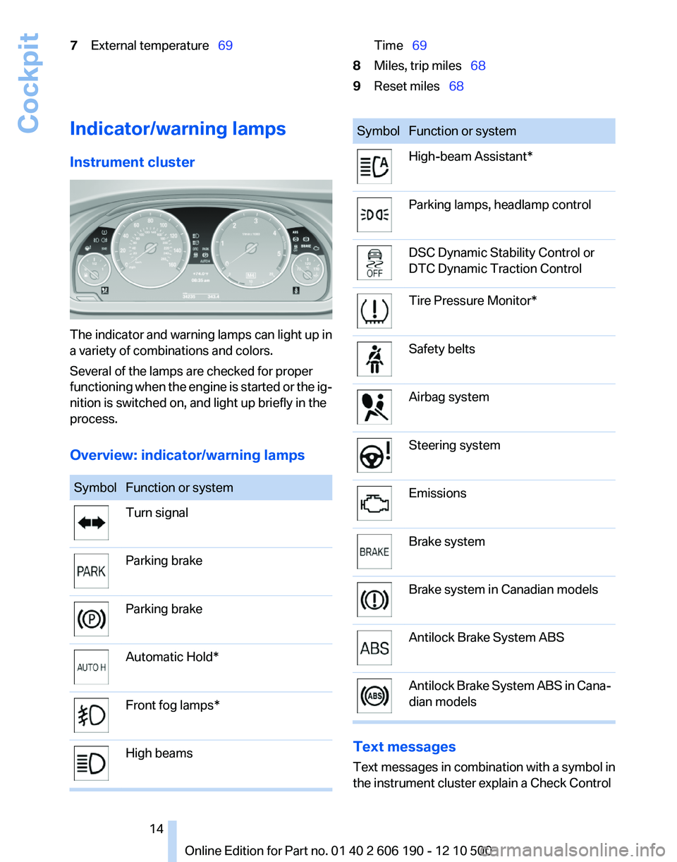
7External temperature 69Time 698Miles, trip miles 689Reset miles 68Indicator/warning lamps
Instrument cluster
The indicator and warning lamps can light up in
a variety of combinations and colors.
Several of the lamps are checked for proper
functioning when the engine is started or the ig‐
nition is switched on, and light up briefly in the
process.
Overview: indicator/warning lamps
SymbolFunction or systemTurn signalParking brakeParking brakeAutomatic Hold*Front fog lamps*High beamsSymbolFunction or systemHigh-beam Assistant*Parking lamps, headlamp controlDSC Dynamic Stability Control or
DTC Dynamic Traction ControlTire Pressure Monitor*Safety beltsAirbag systemSteering systemEmissionsBrake systemBrake system in Canadian modelsAntilock Brake System ABSAntilock Brake System ABS in Cana‐
dian models
Text messages
Text messages in combination with a symbol in
the instrument cluster explain a Check Control
Seite 1414
Online Edition for Part no. 01 40 2 606 190 - 12 10 500Cockpit
Page 58 of 262
DrivingStart/Stop button
The concept Pressing the Start/Stop button
switches the ignition on or off and
starts the engine.
The engine starts if the brake
pedal is pressed when you press
the Start/Stop button.
Ignition on
Press the Start/Stop button and do not press on
the brake pedal at the same time.
All vehicle systems are ready for operation.
Most of the indicator and warning lamps in the
instrument cluster light up for varying lengths of
time.
To save battery power when the engine is off,
switch off the ignition and any unnecessary
electronic systems/power consumers.
The ignition switches off automatically:▷When the vehicle is locked, if the low beams
are switched on.▷Shortly before the battery is discharged
completely, so that the engine can still be
started.▷If the engine is switched off and the ignition
is switched on, the system automatically
switches to the radio ready state when the
door is opened if the lights are switched off
or the daytime running lights are switched
on.
Ignition off
Press the Start/Stop button again and do not
press on the brake pedal at the same time.
All indicator lamps in the instrument cluster go
out.
To save battery power when the engine is off,
switch off the ignition and any unnecessary
electronic systems/power consumers.
Transmission position P with the ignition
off
When the ignition is switched off, position P is
engaged automatically. When in an automatic
car wash, for example, ensure that the ignition is
not switched off accidentally.◀
When the vehicle is locked using the central
locking system, the ignition switches off auto‐
matically.
Radio ready state
This state can only be reached by pressing the
Start/Stop button briefly to switch off the engine
while it is running.
Some electronic systems/power consumers re‐
main ready for operation.
Radio ready state switches off automatically:▷After approx. 8 minutes.▷When the vehicle is locked using the central
locking system.
Starting the engine
General information Enclosed areas
Do not let the engine run in enclosed
areas; otherwise, breathing of exhaust fumes
may lead to loss of consciousness and death.
The exhaust gases contain carbon monoxide, an
odorless and colorless but highly toxic gas.◀
Unattended vehicle
Do not leave the car unattended with the
engine running; otherwise, it presents a poten‐
tial source of danger.
Before leaving the car with the engine running,
set the parking brake and place the transmission
in position P or neutral to prevent the car from
moving.◀
Seite 5858
Online Edition for Part no. 01 40 2 606 190 - 12 10 500Driving
Page 60 of 262
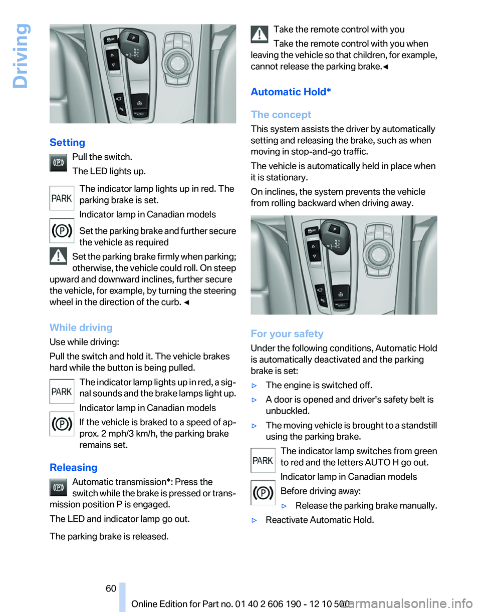
SettingPull the switch.
The LED lights up.
The indicator lamp lights up in red. The
parking brake is set.
Indicator lamp in Canadian models
Set the parking brake and further secure
the vehicle as required
Set the parking brake firmly when parking;
otherwise, the vehicle could roll. On steep
upward and downward inclines, further secure
the vehicle, for example, by turning the steering
wheel in the direction of the curb. ◀
While driving
Use while driving:
Pull the switch and hold it. The vehicle brakes
hard while the button is being pulled.
The indicator lamp lights up in red, a sig‐
nal sounds and the brake lamps light up.
Indicator lamp in Canadian models
If the vehicle is braked to a speed of ap‐
prox. 2 mph/3 km/h, the parking brake
remains set.
Releasing Automatic transmission*: Press the
switch while the brake is pressed or trans‐
mission position P is engaged.
The LED and indicator lamp go out.
The parking brake is released.
Take the remote control with you
Take the remote control with you when
leaving the vehicle so that children, for example,
cannot release the parking brake.◀
Automatic Hold*
The concept
This system assists the driver by automatically
setting and releasing the brake, such as when
moving in stop-and-go traffic.
The vehicle is automatically held in place when
it is stationary.
On inclines, the system prevents the vehicle
from rolling backward when driving away.
For your safety
Under the following conditions, Automatic Hold
is automatically deactivated and the parking
brake is set:
▷The engine is switched off.▷A door is opened and driver's safety belt is
unbuckled.▷The moving vehicle is brought to a standstill
using the parking brake.
The indicator lamp switches from green
to red and the letters AUTO H go out.
Indicator lamp in Canadian models
Before driving away:
▷Release the parking brake manually.▷Reactivate Automatic Hold.Seite 6060
Online Edition for Part no. 01 40 2 606 190 - 12 10 500Driving
Page 61 of 262
Leaving the vehicle with the engine run‐
ning
Before leaving the vehicle with the engine run‐
ning, engage position P of the automatic trans‐
mission and ensure that the parking brake is set.
Otherwise, the vehicle may begin to roll.◀
Activating
This function can be activated when the driver's
door is closed and the safety belt is fastened, or
while driving.
Press the button.
The LED and the letters AUTO H light
up.
The indicator lamp lights up.
Automatic Hold is activated.
Deactivating Press the button again.
The LED and the letters AUTO H go
out.
Automatic Hold is deactivated.
If the vehicle is being held by Automatic Hold,
press on the brake pedal to deactivate it.
When the parking brake, refer to page 59, is set
manually, Automatic Hold is deactivated auto‐
matically.
Driving
Automatic Hold is activated: the vehicle is auto‐
matically secured against rolling when it stops.
The indicator lamp lights up in green.
Step on the accelerator pedal to drive
off.
The brake is released automatically.
The indicator lamp goes out.
Lower lamp: indicator lamp in Canadian models
Before driving into a car wash
Deactivate Automatic Hold; otherwise, the
parking brake will be set when the vehicle is sta‐
tionary and the vehicle will no longer be able to
roll.◀Parking
The parking brake is automatically set if the en‐
gine is switched off while the vehicle is being
held by Automatic Hold.
The indicator lamp changes from green
to red.
The parking brake is not set if the engine
is switched off while the vehicle is coast‐
ing to a halt. Automatic Hold is deacti‐
vated.
Take the remote control with you
Take the remote control with you when
leaving the vehicle so that children, for example,
cannot release the parking brake.◀
Malfunction
In the event of a failure or malfunction of the
parking brake, secure the vehicle against rolling
using a wheel chock, for example, when leaving
it.
Turn signal, high beams,
headlamp flasher
Turn signal
Using turn signals
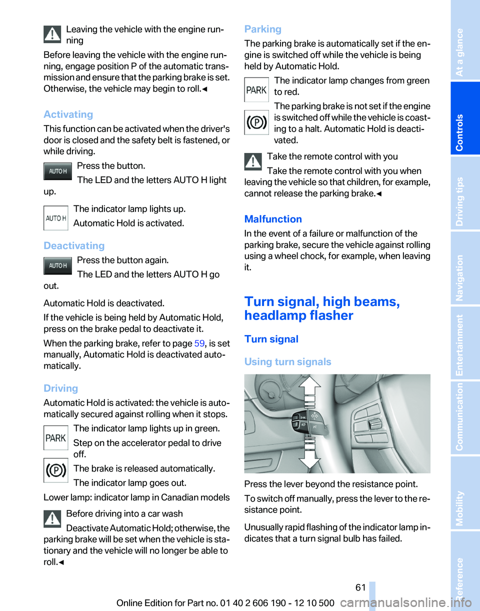
Press the lever beyond the resistance point.
To switch off manually, press the lever to the re‐
sistance point.
Unusually rapid flashing of the indicator lamp in‐
dicates that a turn signal bulb has failed.
Seite 6161
Online Edition for Part no. 01 40 2 606 190 - 12 10 500
ReferenceMobilityCommunicationEntertainmentNavigationDriving tipsControlsAt a glance
Page 85 of 262
the vehicle manufacturer on the vehicle placard
or tire inflation pressure label. (If your vehicle has
tires of a different size than the size indicated on
the vehicle placard or tire inflation pressure la‐
bel, you should determine the proper tire infla‐
tion pressure for those tires.) As an added safety
feature, your vehicle has been equipped with a
tire pressure monitoring system (TPMS) that il‐
luminates a low tire pressure telltale when one
or more of your tires is significantly under-in‐
flated. Accordingly, when the low tire pressure
telltale illuminates, you should stop and check
your tires as soon as possible, and inflate them
to the proper pressure. Driving on a significantly
under-inflated tire causes the tire to overheat
and can lead to tire failure. Under-inflation also
reduces fuel efficiency and tire tread life, and
may affect the vehicle's handling and stopping
ability. Please note that the TPMS is not a sub‐
stitute for proper tire maintenance, and it is the
driver's responsibility to maintain correct tire
pressure, even if under-inflation has not reached
the level to trigger illumination of the TPMS low
tire pressure telltale. Your vehicle has also been
equipped with a TPMS malfunction indicator to
indicate when the system is not operating prop‐
erly. The TPMS malfunction indicator is com‐
bined with the low tire pressure telltale. When
the system detects a malfunction, the telltale will
flash for approximately one minute and then re‐
main continuously illuminated. This sequence
will continue upon subsequent vehicle start-ups
as long as the malfunction exists. When the mal‐
function indicator is illuminated, the system may
not be able to detect or signal low tire pressure
as intended. TPMS malfunctions may occur for
a variety of reasons, including the installation of
replacement or alternate tires or wheels on the
vehicle that prevent the TPMS from functioning
properly. Always check the TPMS malfunction
telltale after replacing one or more tires or
wheels on your vehicle to ensure that the re‐
placement or alternate tires and wheels allow
the TPMS to continue to function properly.Brake force display*
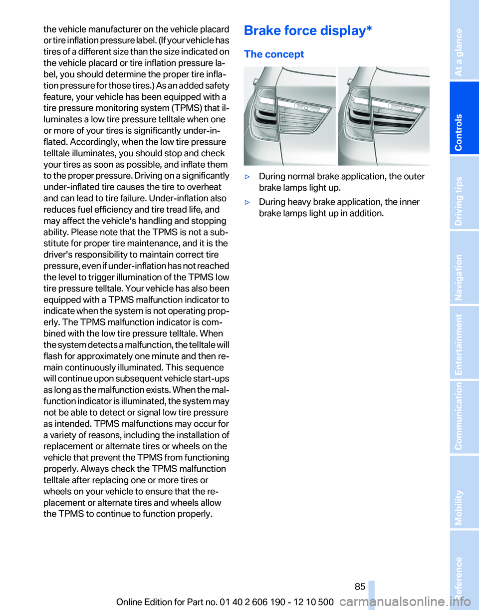
The concept▷During normal brake application, the outer
brake lamps light up.▷During heavy brake application, the inner
brake lamps light up in addition.Seite 8585
Online Edition for Part no. 01 40 2 606 190 - 12 10 500
ReferenceMobilityCommunicationEntertainmentNavigationDriving tipsControlsAt a glance
Page 86 of 262
Driving stability control systemsAntilock Brake System ABS
ABS prevents locking of the wheels during brak‐
ing.
The vehicle remains steerable even during full
brake applications, thus increasing active
safety.
ABS is operational every time you start the en‐
gine.
Brake assistant
When you apply the brakes rapidly, this system
automatically produces the maximum braking
force boost. It thus helps to achieve the shortest
possible braking distance during full braking.
This system utilizes all of the benefits provided
by ABS.
Do not reduce the pressure on the brake pedal
for the duration of the full braking.
DSC Dynamic Stability
Control
The concept
DSC prevents traction loss in the driving wheels
when driving away and accelerating.
DSC also recognizes unstable vehicle condi‐
tions, such as fishtailing or nose-diving. Subject
to physical limits, DSC helps to keep the vehicle
on a steady course by reducing engine speed
and by applying brakes at individual wheels.
Adjust your driving style to the situation
An appropriate driving style is always the
responsibility of the driver.
The laws of physics cannot be repealed, even
with DSC.
Therefore, do not reduce the additional safety
margin by driving in a risky manner.◀Indicator/warning lamps
The indicator lamp flashes: DSC con‐
trols the drive forces and brake forces.
The indicator lamp lights up: DSC has
failed.
Deactivating DSC: DSC OFF
When DSC is deactivated, driving stability is re‐
duced during acceleration and when driving in
bends.
To increase vehicle stability, activate DSC again
as soon as possible.
Deactivating DSC Press and hold the button, but not lon‐
ger than approx. 10 seconds, until the
indicator lamp for DSC lights up in the instru‐
ment cluster and DSC OFF is displayed.
The DSC system is switched off.
Activating DSC Press the button.
DSC OFF and the DSC indicator lamp
go out.
Indicator/warning lamps
When DSC is deactivated, DSC OFF is dis‐
played in the instrument cluster.
The indicator lamp lights up: DSC is de‐
activated.
DTC Dynamic Traction
Control
The concept
The DTC system is a version of the DSC in which
forward momentum is optimized.Seite 8686
Online Edition for Part no. 01 40 2 606 190 - 12 10 500Driving stability control systems
Page 87 of 262
The system ensures maximum forward momen‐
tum on special road conditions, e.g., unplowed
snowy roads, but driving stability is limited.
It is therefore necessary to drive with appropri‐
ate caution.
You may find it useful to briefly activate DTC un‐
der the following special circumstances:▷When driving in slush or on uncleared,
snow-covered roads.▷When rocking the vehicle or driving off in
deep snow or on loose surfaces.▷When driving with snow chains.
Deactivating/activating DTC Dynamic
Traction Control
Activating the Dynamic Traction Control DTC
provides maximum traction on loose ground.
Driving stability is limited during acceleration
and when driving in bends.
Activating DTC Press the button.
TRACTION is displayed in the instru‐
ment cluster and the indicator lamp for DSC
lights up.
Deactivating DTC Press the button again.
TRACTION and the DSC indicator lamp
go out.
Performance Control*
Performance Control enhances the agility of
your vehicle.
To enhance performance during sporty driving,
the rear wheel on the inside of the curve is
braked while the resulting braking effect is
largely compensated by engine intervention.
xDrive
xDrive is the all-wheel-drive system of your ve‐
hicle. Concerted action by the xDrive and DSC
further optimize traction and driving dynamics.
The xDrive all-wheel-drive system variably dis‐
tributes the drive forces to the front and rear
axles as demanded by the driving situation and
road surface.
HDC Hill Descent Control
The concept
HDC is a downhill driving assistant that auto‐
matically controls vehicle speed on steep down‐
hill gradients. Without requiring brake applica‐
tion, the vehicle moves at slightly more than
twice walking speed.
You can activate the Hill Descent Control at
speeds below approx. 22 mph/35 km/h. When
driving downhill, the vehicle reduces its speed
to approx. twice walking speed and then keeps
its speed constant.
While you are actively braking, the system is on
standby. The system does not brake the vehicle
during this time.
Use HDC in low gears or in transmission position
D or R only.
Changing the speed
The speed can be changed in the range from
roughly twice walking speed to approx. 15 mph/
25 km/h by lightly pressing the accelerator.
To set the speed: buttons* on the
steering wheel
The desired speed can be specified in the range
from roughly twice walking speed to approx.
15 mph/25 km/h using the rocker switch of the
cruise control on the steering wheel.Seite 8787
Online Edition for Part no. 01 40 2 606 190 - 12 10 500
ReferenceMobilityCommunicationEntertainmentNavigationDriving tipsControlsAt a glance
Page 88 of 262
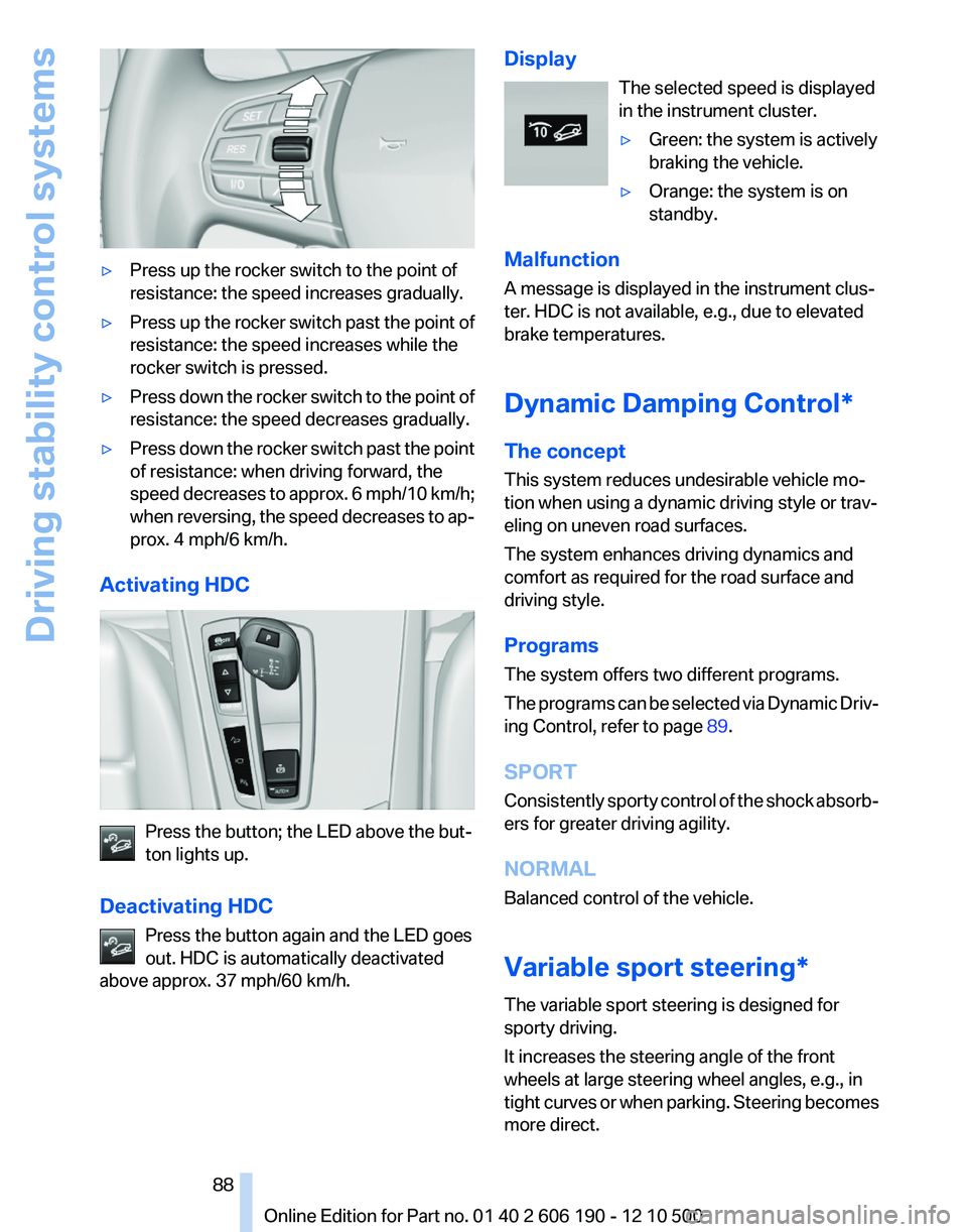
▷Press up the rocker switch to the point of
resistance: the speed increases gradually.▷Press up the rocker switch past the point of
resistance: the speed increases while the
rocker switch is pressed.▷Press down the rocker switch to the point of
resistance: the speed decreases gradually.▷Press down the rocker switch past the point
of resistance: when driving forward, the
speed decreases to approx. 6 mph/10 km/h;
when reversing, the speed decreases to ap‐
prox. 4 mph/6 km/h.
Activating HDC
Press the button; the LED above the but‐
ton lights up.
Deactivating HDC Press the button again and the LED goes
out. HDC is automatically deactivated
above approx. 37 mph/60 km/h.
Display
The selected speed is displayed
in the instrument cluster.▷Green: the system is actively
braking the vehicle.▷Orange: the system is on
standby.
Malfunction
A message is displayed in the instrument clus‐
ter. HDC is not available, e.g., due to elevated
brake temperatures.
Dynamic Damping Control*
The concept
This system reduces undesirable vehicle mo‐
tion when using a dynamic driving style or trav‐
eling on uneven road surfaces.
The system enhances driving dynamics and
comfort as required for the road surface and
driving style.
Programs
The system offers two different programs.
The programs can be selected via Dynamic Driv‐
ing Control, refer to page 89.
SPORT
Consistently sporty control of the shock absorb‐
ers for greater driving agility.
NORMAL
Balanced control of the vehicle.
Variable sport steering*
The variable sport steering is designed for
sporty driving.
It increases the steering angle of the front
wheels at large steering wheel angles, e.g., in
tight curves or when parking. Steering becomes
more direct.
Seite 8888
Online Edition for Part no. 01 40 2 606 190 - 12 10 500Driving stability control systems
Page 92 of 262
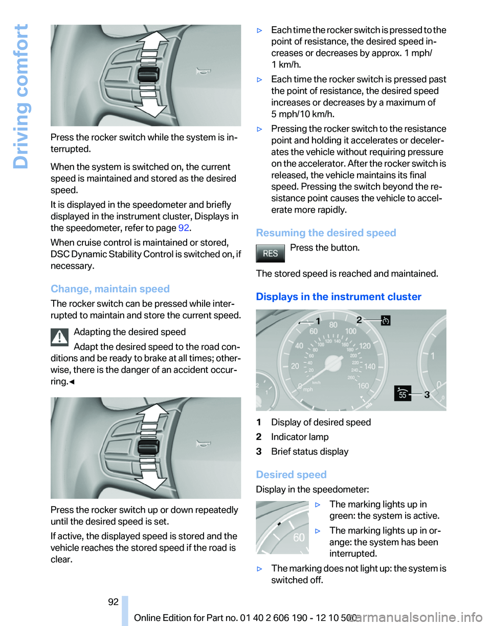
Press the rocker switch while the system is in‐
terrupted.
When the system is switched on, the current
speed is maintained and stored as the desired
speed.
It is displayed in the speedometer and briefly
displayed in the instrument cluster, Displays in
the speedometer, refer to page 92.
When cruise control is maintained or stored,
DSC Dynamic Stability Control is switched on, if
necessary.
Change, maintain speed
The rocker switch can be pressed while inter‐
rupted to maintain and store the current speed.
Adapting the desired speed
Adapt the desired speed to the road con‐
ditions and be ready to brake at all times; other‐
wise, there is the danger of an accident occur‐
ring.◀
Press the rocker switch up or down repeatedly
until the desired speed is set.
If active, the displayed speed is stored and the
vehicle reaches the stored speed if the road is
clear.
▷Each time the rocker switch is pressed to the
point of resistance, the desired speed in‐
creases or decreases by approx. 1 mph/
1 km/h.▷Each time the rocker switch is pressed past
the point of resistance, the desired speed
increases or decreases by a maximum of
5 mph/10 km/h.▷Pressing the rocker switch to the resistance
point and holding it accelerates or deceler‐
ates the vehicle without requiring pressure
on the accelerator. After the rocker switch is
released, the vehicle maintains its final
speed. Pressing the switch beyond the re‐
sistance point causes the vehicle to accel‐
erate more rapidly.
Resuming the desired speed
Press the button.
The stored speed is reached and maintained.
Displays in the instrument cluster
1Display of desired speed2Indicator lamp3Brief status display
Desired speed
Display in the speedometer:
▷The marking lights up in
green: the system is active.▷The marking lights up in or‐
ange: the system has been
interrupted.▷The marking does not light up: the system is
switched off.Seite 9292
Online Edition for Part no. 01 40 2 606 190 - 12 10 500Driving comfort
Page 122 of 262
Avoid load on the brakes
Avoid placing excessive load on the brake
system. Light but consistent brake pressure can
lead to high temperatures, brake wear and pos‐
sibly even brake failure.◀
Do not drive in neutral
Do not drive in neutral or with the engine
stopped, as doing so disables engine braking. In
addition, steering and brake assist is unavailable
with the engine stopped.◀
Brake disc corrosion
Corrosion on the brake discs and contamination
on the brake pads are furthered by:▷Low mileage.▷Extended periods when the vehicle is not
used at all.▷Infrequent use of the brakes.
Corrosion occurs when the minimum pressure
that must be exerted by the pads during brake
applications to clean the discs is not reached.
Should corrosion form on the brake discs, the
brakes will tend to respond with a pulsating ef‐
fect that generally cannot be corrected.
Condensation under the parked vehicle
When using the automatic climate control, con‐
densation water develops that exits underneath
the vehicle.
Therefore, traces of condensed water under the
vehicle are normal.
Loading Overloading the vehicle
To avoid exceeding the approved carrying
capacity of the tires, never overload the vehicle.
Overloading can lead to overheating and in‐
creases the rate at which damage develops in‐
side the tires. This could result in a sudden loss
of tire inflation pressure.◀
No fluids in the trunk
Make sure that fluids do not leak into the
trunk; otherwise, the vehicle may be damaged. ◀
Determining the load limit1.Locate the following statement on your ve‐
hicle’s placard*:▷The combined weight of occupants and
cargo should never exceed XXX kg or
YYY lbs. Otherwise, damage to the ve‐
hicle and unstable driving situations may
result.2.Determine the combined weight of the
driver and passengers that will be riding in
your vehicle.3.Subtract the combined weight of the driver
and passengers from XXX kilograms or YYY
pounds.4.The resulting figure equals the available
amount of cargo and luggage load capacity.
For example, if the YYY amount equals
1,400 lbs and there will be five 150 lbs pas‐
sengers in your vehicle, the amount of avail‐
able cargo and luggage load capacity is
650 lbs: 1,400 lbs minus 750 lbs = 650 lbs.5.Determine the combined weight of luggage
and cargo being loaded on the vehicle. That
weight may not safely exceed the available
cargo and luggage load capacity calculated
in Step 4.Seite 122122
Online Edition for Part no. 01 40 2 606 190 - 12 10 500Things to remember when driving