service indicator BMW X4 2016 F26 Owner's Manual
[x] Cancel search | Manufacturer: BMW, Model Year: 2016, Model line: X4, Model: BMW X4 2016 F26Pages: 253, PDF Size: 5.21 MB
Page 83 of 253
▷Messages, e.g. Check Control, refer to
page 83.▷Navigation display, see User's manual for
Navigation, Entertainment and Communi‐
cation.▷Range, refer to page 88.▷Status, Driving Dynamics Control, refer to
page 130.▷Service requirements, refer to page 89.▷Speed limit detection, refer to page 90.▷Time, refer to page 87.
Check Control
The concept The Check Control system monitors functions
in the vehicle and notifies you of malfunctions
in the monitored systems.
A Check Control message is displayed as a
combination of indicator or warning lights and
text messages in the instrument cluster and in
the Head-up Display.
In addition, an acoustic signal may sound and a text message may appear on the Control Dis‐
play.
Indicator/warning lights
General information
The indicator and warning lights in the instru‐
ment cluster can light up in a variety of combi‐
nations and colors.
Several of the lights are checked for proper
functioning and light up temporarily when the
engine is started or the ignition is switched on.
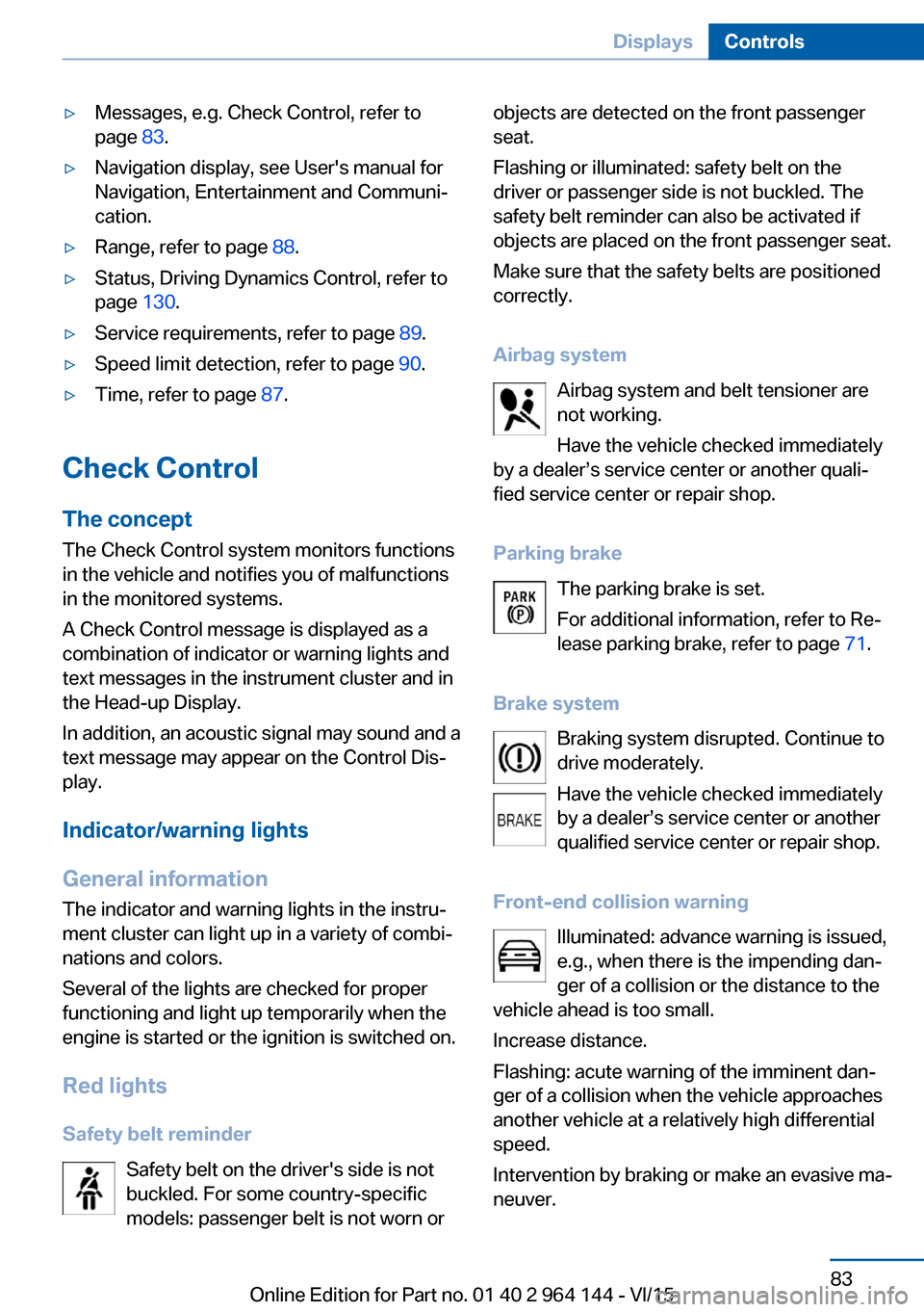
Red lights Safety belt reminder Safety belt on the driver's side is not
buckled. For some country-specific
models: passenger belt is not worn or
objects are detected on the front passenger
seat.
Flashing or illuminated: safety belt on the
driver or passenger side is not buckled. The
safety belt reminder can also be activated if
objects are placed on the front passenger seat.
Make sure that the safety belts are positioned
correctly.
Airbag system Airbag system and belt tensioner are
not working.
Have the vehicle checked immediately
by a dealer’s service center or another quali‐
fied service center or repair shop.
Parking brake The parking brake is set.
For additional information, refer to Re‐ lease parking brake, refer to page 71.
Brake system Braking system disrupted. Continue to
drive moderately.
Have the vehicle checked immediately
by a dealer’s service center or another qualified service center or repair shop.
Front-end collision warning Illuminated: advance warning is issued,
e.g., when there is the impending dan‐
ger of a collision or the distance to the
vehicle ahead is too small.
Increase distance.
Flashing: acute warning of the imminent dan‐
ger of a collision when the vehicle approaches
another vehicle at a relatively high differential
speed.
Intervention by braking or make an evasive ma‐
neuver.Seite 83DisplaysControls83
Online Edition for Part no. 01 40 2 964 144 - VI/15
Page 85 of 253
▷TPM could not conclude the reset: perform
the reset of the system again.▷A wheel without TPM electronics is
mounted: Have it checked by a dealer’s
service center or another qualified service
center or repair shop as needed.▷Malfunction: Have system checked imme‐
diately by a dealer’s service center or an‐
other qualified service center or repair
shop.
For more information, see Tire Pressure Moni‐
tor, refer to page 106.
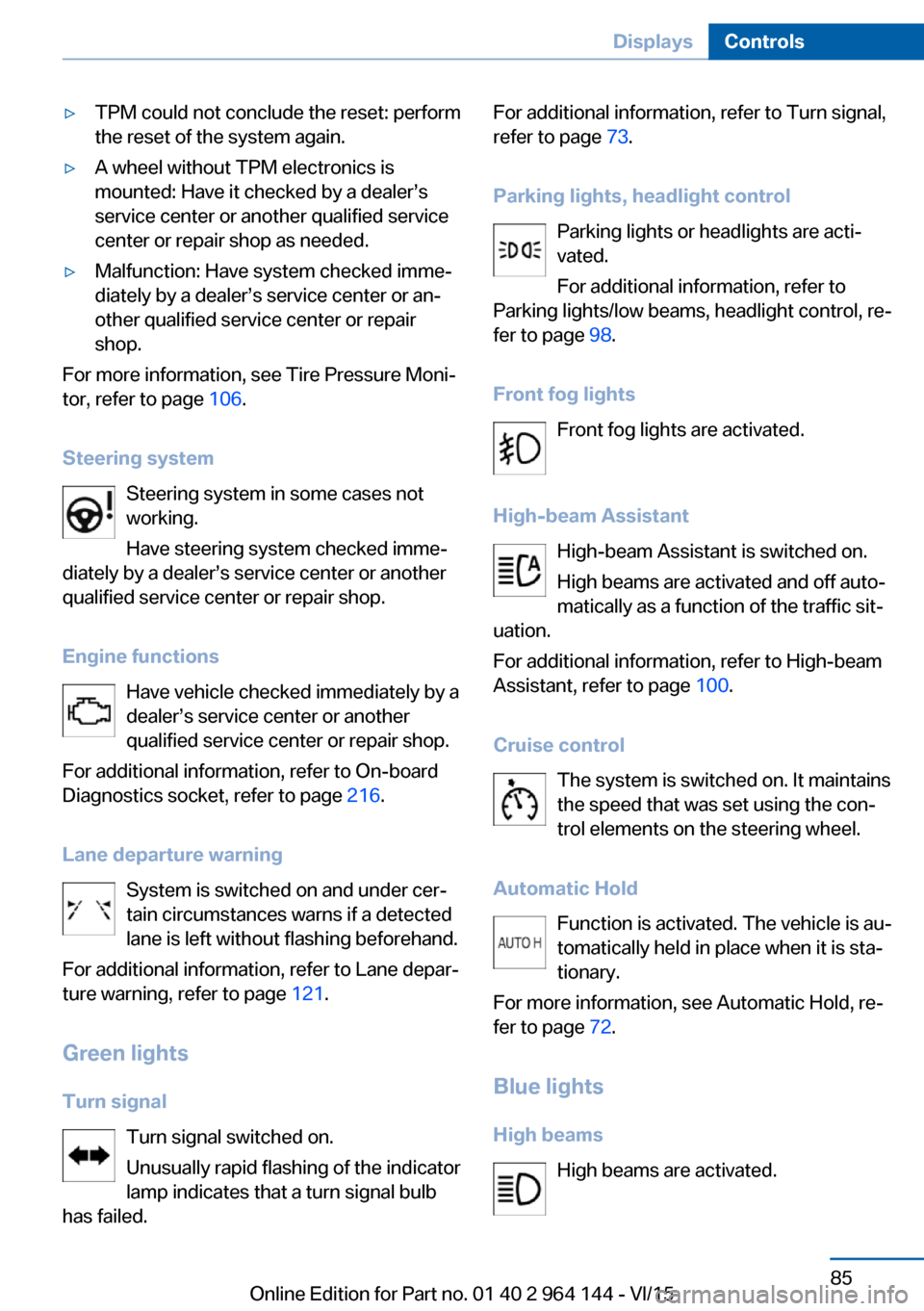
Steering system Steering system in some cases not
working.
Have steering system checked imme‐
diately by a dealer’s service center or another
qualified service center or repair shop.
Engine functions Have vehicle checked immediately by a
dealer’s service center or another
qualified service center or repair shop.
For additional information, refer to On-board
Diagnostics socket, refer to page 216.
Lane departure warning System is switched on and under cer‐
tain circumstances warns if a detected
lane is left without flashing beforehand.
For additional information, refer to Lane depar‐
ture warning, refer to page 121.
Green lights Turn signal Turn signal switched on.
Unusually rapid flashing of the indicator
lamp indicates that a turn signal bulb
has failed.
For additional information, refer to Turn signal,
refer to page 73.
Parking lights, headlight control Parking lights or headlights are acti‐
vated.
For additional information, refer to
Parking lights/low beams, headlight control, re‐
fer to page 98.
Front fog lights Front fog lights are activated.
High-beam Assistant High-beam Assistant is switched on.
High beams are activated and off auto‐
matically as a function of the traffic sit‐
uation.
For additional information, refer to High-beam
Assistant, refer to page 100.
Cruise control The system is switched on. It maintains
the speed that was set using the con‐
trol elements on the steering wheel.
Automatic Hold Function is activated. The vehicle is au‐
tomatically held in place when it is sta‐
tionary.
For more information, see Automatic Hold, re‐
fer to page 72.
Blue lights
High beams High beams are activated.Seite 85DisplaysControls85
Online Edition for Part no. 01 40 2 964 144 - VI/15
Page 86 of 253
For additional information, refer to High
beams, refer to page 74.
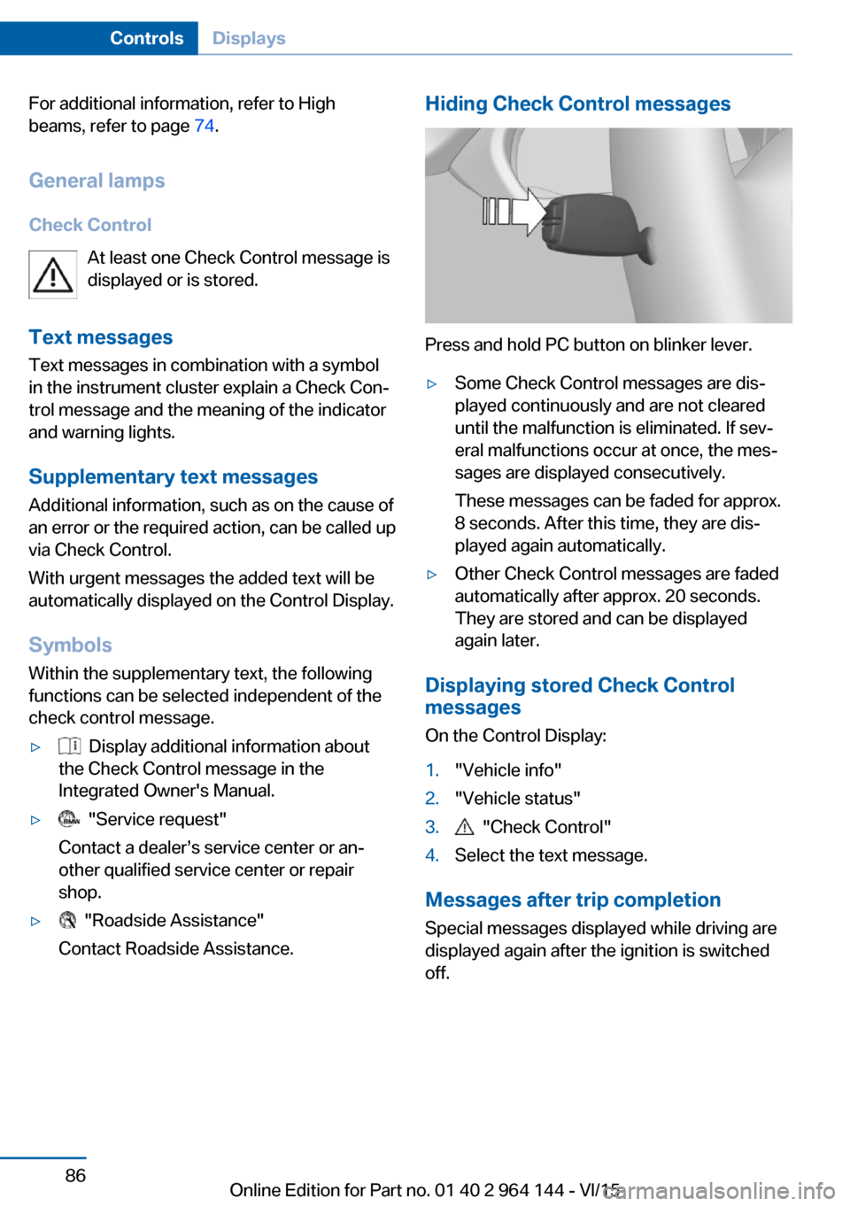
General lamps Check Control At least one Check Control message is
displayed or is stored.
Text messages Text messages in combination with a symbol
in the instrument cluster explain a Check Con‐
trol message and the meaning of the indicator
and warning lights.
Supplementary text messagesAdditional information, such as on the cause of
an error or the required action, can be called up
via Check Control.
With urgent messages the added text will be
automatically displayed on the Control Display.
Symbols
Within the supplementary text, the following
functions can be selected independent of the
check control message.▷ Display additional information about
the Check Control message in the
Integrated Owner's Manual.▷ "Service request"
Contact a dealer’s service center or an‐
other qualified service center or repair
shop.▷ "Roadside Assistance"
Contact Roadside Assistance.Hiding Check Control messages
Press and hold PC button on blinker lever.
▷Some Check Control messages are dis‐
played continuously and are not cleared
until the malfunction is eliminated. If sev‐
eral malfunctions occur at once, the mes‐
sages are displayed consecutively.
These messages can be faded for approx.
8 seconds. After this time, they are dis‐
played again automatically.▷Other Check Control messages are faded
automatically after approx. 20 seconds.
They are stored and can be displayed
again later.
Displaying stored Check Control
messages
On the Control Display:
1."Vehicle info"2."Vehicle status"3. "Check Control"4.Select the text message.
Messages after trip completion Special messages displayed while driving are
displayed again after the ignition is switched
off.
Seite 86ControlsDisplays86
Online Edition for Part no. 01 40 2 964 144 - VI/15
Page 89 of 253
Service requirements
The concept After the ignition is turned on the instrument
cluster briefly displays available driving dis‐
tance or time to the next scheduled mainte‐
nance.
A service advisor can read out the current
service requirements from your remote con‐
trol.
Display
Detailed information on service
requirements
More information on the scope of service re‐
quired can be displayed on the Control Dis‐
play.1."Vehicle info"2."Vehicle status"3. "Service required"
Required maintenance procedures and le‐
gally mandated inspections are displayed.4.Select an entry to call up detailed informa‐
tion.
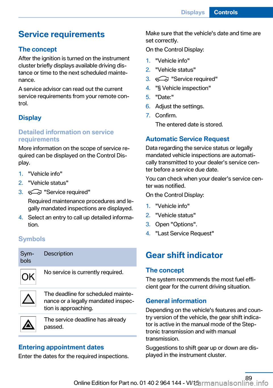
Symbols
Sym‐
bolsDescriptionNo service is currently required.The deadline for scheduled mainte‐
nance or a legally mandated inspec‐
tion is approaching.The service deadline has already
passed.
Entering appointment dates
Enter the dates for the required inspections.
Make sure that the vehicle's date and time are
set correctly.
On the Control Display:1."Vehicle info"2."Vehicle status"3. "Service required"4."§ Vehicle inspection"5."Date:"6.Adjust the settings.7.Confirm.
The entered date is stored.
Automatic Service Request
Data regarding the service status or legally
mandated vehicle inspections are automati‐
cally transmitted to your dealer’s service cen‐
ter before a service due date.
You can check when your dealer’s service cen‐
ter was notified.
On the Control Display:
1."Vehicle info"2."Vehicle status"3.Open "Options".4."Last Service Request"
Gear shift indicator
The conceptThe system recommends the most fuel effi‐
cient gear for the current driving situation.
General information
Depending on the vehicle's features and coun‐
try version of the vehicle, the gear shift indica‐
tor is active in the manual mode of the Step‐
tronic transmission and with manual
transmission.
Suggestions to shift gear up or down are dis‐
played in the instrument cluster.
Seite 89DisplaysControls89
Online Edition for Part no. 01 40 2 964 144 - VI/15
Page 105 of 253
injuries or danger to life. Have the airbag sys‐
tem checked, repaired, dismantled and scrap‐
ped by a dealer’s service center or another
qualified service center or repair shop.◀
Correct function When the ignition is switched on, the
warning lamp in the instrument cluster
lights up briefly and thereby indicates
the operational readiness of the entire airbag
system and the belt tensioner.
Airbag system malfunctioning▷Warning lamp does not come on when the
ignition is turned on.▷The warning lamp lights up continuously.
Automatic deactivation of the front-
seat passenger airbags
The concept The system reads if the front passenger seat is
occupied by measuring the human body's re‐
sistance.
Front, knee and side airbag on the front pas‐
senger's side are either activated or deacti‐
vated.
Information Before transporting a child on the front pas‐
senger seat, refer to the safety notes and in‐
structions for children on the front passenger
seat, see Children.
WARNING
The ensure the front-seat passenger air‐
bag function, it must be detected, whether a
person occupies the front passenger seat. The
entire seat cushion area must be used for this
purpose. There is risk of injuries or danger to
life. Make sure that the front passenger keeps
his or her feet in the floor area.◀
Malfunction of the automatic
deactivation system
When transporting older children and adults,
the front-seat passenger airbags may be deac‐
tivated in certain sitting positions. In this case,
the indicator lamp for the front-seat passenger
airbags lights up.
In this case, change the sitting position so that
the front-seat passenger airbags are activated
and the indicator lamp goes out.
If it is not possible to activate the airbags, have
the person sit in the rear.
To enable correct recognition of the occupied
seat cushion▷Do not attach covers, cushions, ball mats
or other items to the front passenger seat
unless they are specifically determined to
be safe for use on the front passenger
seat.▷Do not place any electronic devices on the
passenger seat if a child restraint system is
to be installed on it.▷Do not place objects under the seat that
could press against the seat from below.▷No moisture in or on the seat.
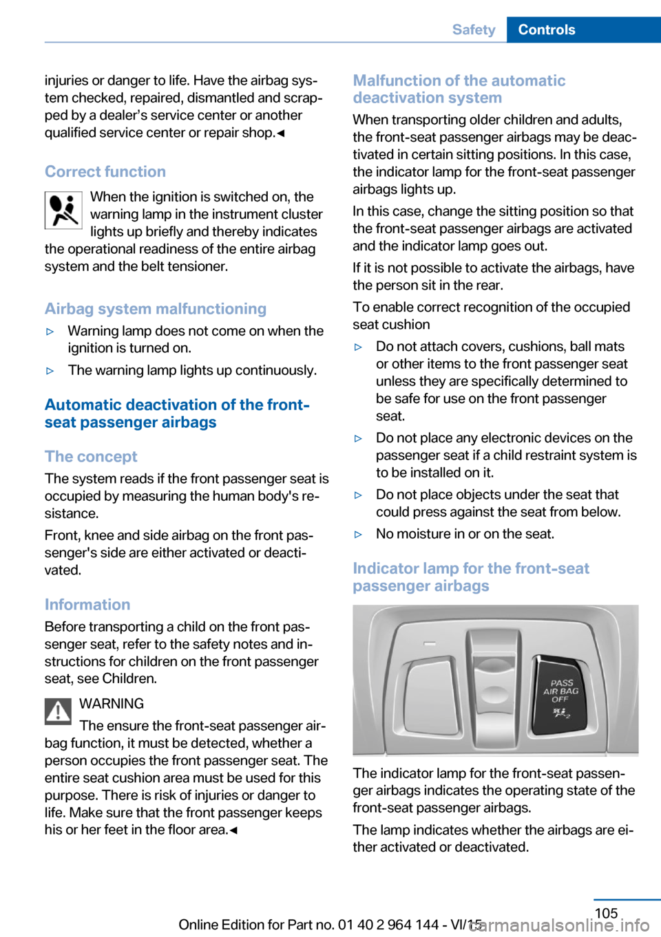
Indicator lamp for the front-seat
passenger airbags
The indicator lamp for the front-seat passen‐
ger airbags indicates the operating state of the
front-seat passenger airbags.
The lamp indicates whether the airbags are ei‐
ther activated or deactivated.
Seite 105SafetyControls105
Online Edition for Part no. 01 40 2 964 144 - VI/15
Page 112 of 253
WARNING
Your vehicle handles differently when a
run-flat tire is damaged and has low or missing
tire inflation pressure, e.g., your lane stability is
reduced when braking, braking distances are
longer and the self-steering properties will
change. There is risk of an accident.
Drive moderately and do not exceed a speed of
50 mph/80 km/h.◀
Final tire failure
Vibrations or loud noises while driving can indi‐
cate the final failure of a tire.
Reduce speed and stop; otherwise, pieces of
the tire could come loose and cause an acci‐
dent.
Do not continue driving. Contact a dealer’s
service center or another qualified service cen‐
ter or repair shop.
Intelligent Safety The concept
Intelligent Safety enables central operation of
the driver assistance system. Depending on
how the vehicle is equipped, Intelligent Safety
consists of one or more systems that can help
prevent a imminent collision.▷Front-end collision warning, refer to
page 113.▷Pedestrian warning, refer to page 119.▷Lane departure warning, refer to
page 121.▷Active Blind Spot Detection, refer to
page 123.
Information
WARNING
Indicators and warnings do not relieve
from the personal responsibility. Due to sys‐
tem limits, warnings or reactions of the system
may not be output or they may be output too
late or incorrectly. There is risk of an accident.
Adjust the driving style to the traffic condi‐
tions. Watch traffic closely and actively inter‐
fere in the respective situations.◀
WARNING
Due to system limits, individual functions
can malfunction during tow-starting/towing
with the Intelligent Safety systems activated,
e.g. approach control warning with light brak‐
ing function. There is risk of an accident.
Switch all Intelligent Safety systems off prior to
tow-starting/towing.◀
Overview
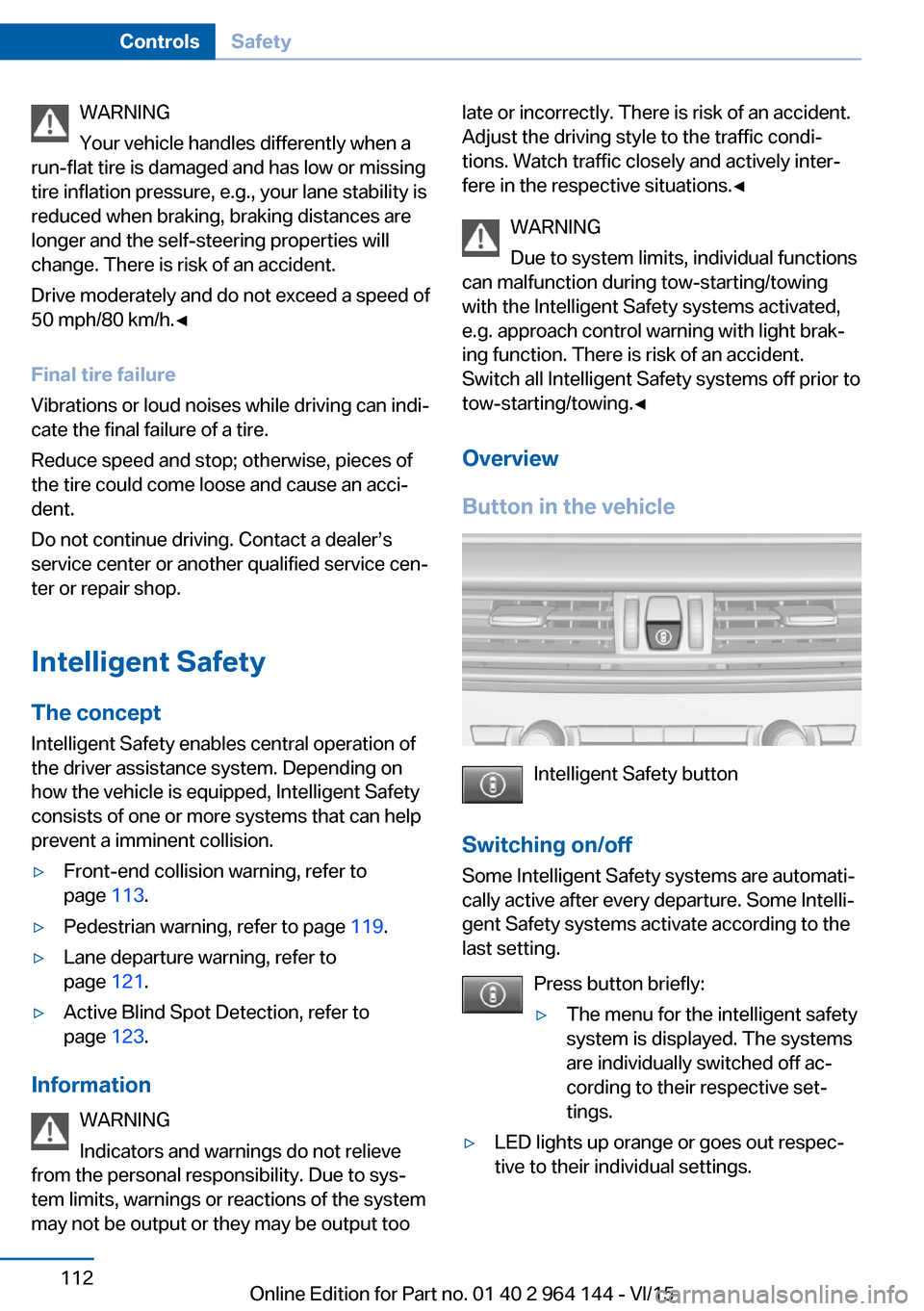
Button in the vehicle
Intelligent Safety button
Switching on/off Some Intelligent Safety systems are automati‐
cally active after every departure. Some Intelli‐
gent Safety systems activate according to the
last setting.
Press button briefly:
▷The menu for the intelligent safety
system is displayed. The systems
are individually switched off ac‐
cording to their respective set‐
tings.▷LED lights up orange or goes out respec‐
tive to their individual settings.Seite 112ControlsSafety112
Online Edition for Part no. 01 40 2 964 144 - VI/15
Page 184 of 253
Avoid high engine speeds
As a rule: driving at low engine speeds lowers
fuel consumption and reduces wear.
Use 1st gear to get the vehicle moving. Start‐
ing with the 2nd gear, accelerate rapidly. When
accelerating, shift up before reaching high en‐
gine speeds.
When you reach the desired speed, shift into
the highest applicable gear and drive with the
engine speed as low as possible and at a con‐
stant speed.
If necessary, observe the gear shift indicator of
the vehicle, refer to page 89.
Use coasting
When approaching a red light, take your foot
off the accelerator and let the vehicle coast to
a halt.
For going downhill take your foot off the accel‐
erator and let the vehicle roll.
The flow of fuel is interrupted while coasting.
Switch off the engine during longer stops
Switch off the engine during longer stops, e.g.,
at traffic lights, railroad crossings or in traffic
congestion.
Auto Start/Stop function The Auto Start/Stop function of your vehicle
automatically switches off the engine during a
stop.
If the engine is switched off and then restarted
rather than leaving the engine running con‐
stantly, fuel consumption and emissions are
reduced. Savings can begin within a few sec‐
onds of switching off the engine.
In addition, fuel consumption is also deter‐
mined by other factors, such as driving style,road conditions, maintenance or environmental
factors.
Switch off any functions that
are not currently needed
Functions such as seat heating and the rear
window defroster require a lot of energy and
reduce the range, especially in city and stop-
and-go traffic.
Switch off these functions if they are not needed.
The ECO PRO driving program supports the
energy conserving use of comfort features.
These functions are automatically deactivated
partially or completely.
Have maintenance carriedout
Have vehicles maintained regularly to achieve
optimal vehicle efficiency and service life.
BMW recommends that maintenance work be
performed by a BMW dealer’s service center.
For information on the BMW Maintenance
System, refer to page 215.
ECO PRO
The concept ECO PRO supports a driving style that saves
on fuel consumption. For this purpose, the en‐
gine control and comfort features, e. g. the cli‐
mate control output, are adjusted.
Under certain conditions the engine is auto‐
matically decoupled from the transmission in
the D selector lever position. The vehicle con‐
tinues traveling with the engine idling to re‐
duce fuel consumption. Selector lever position
D remains engaged.Seite 184Driving tipsSaving fuel184
Online Edition for Part no. 01 40 2 964 144 - VI/15
Page 200 of 253
cantly from the norm due to variations in driv‐
ing habits, service practices and differences in
road characteristics and climate.
Traction
The traction grades, from highest to lowest,
are AA, A, B, and C.
Those grades represent the tire's ability to
stop on wet pavement as measured under
controlled conditions on specified government
test surfaces of asphalt and concrete. A tire
marked C may have poor traction performance.
The traction grade assigned to this tire is
based on straight-ahead braking traction tests,
and does not include acceleration, cornering,
hydroplaning, or peak traction characteristics.
Temperature
The temperature grades are A, the highest, B, and C, representing the tire's resistance to the
generation of heat and its ability to dissipate
heat when tested under controlled conditions
on a specified indoor laboratory test wheel.
Sustained high temperature can cause the ma‐
terial of the tire to degenerate and reduce tire
life, and excessive temperature can lead to
sudden tire failure. The grade C corresponds
to a level of performance which all passenger
car tires must meet under the Federal Motor
Vehicle Safety Standard No. 109. Grades Band
A represent higher levels of performance on
the laboratory test wheel than the minimum re‐
quired by law.
WARNING
The temperature grade for this tire is es‐
tablished for a tire that is properly inflated and
not overloaded. Excessive speed, underinfla‐
tion, or excessive loading, either separately or
in combination, can cause heat buildup and
possible tire failure.◀RSC – Run-flat tires
Run-flat tires, refer to page 202, are labeled
with a circular symbol containing the letters
RSC marked on the sidewall.
M+S Winter and all-season tires with better cold
weather performance than summer tires.
Tire tread Summer tires
Do not drive with a tire tread depth of less than
0.12 in/3 mm.
There is an increased danger of hydroplaning if
the tire tread depth is less than 0.12 in/3 mm.
Winter tires Do not drive with a tire tread depth of less than
0.16 in/4 mm.
Below a tread depth of 0.16 in/4 mm, tires are
less suitable for winter operation.
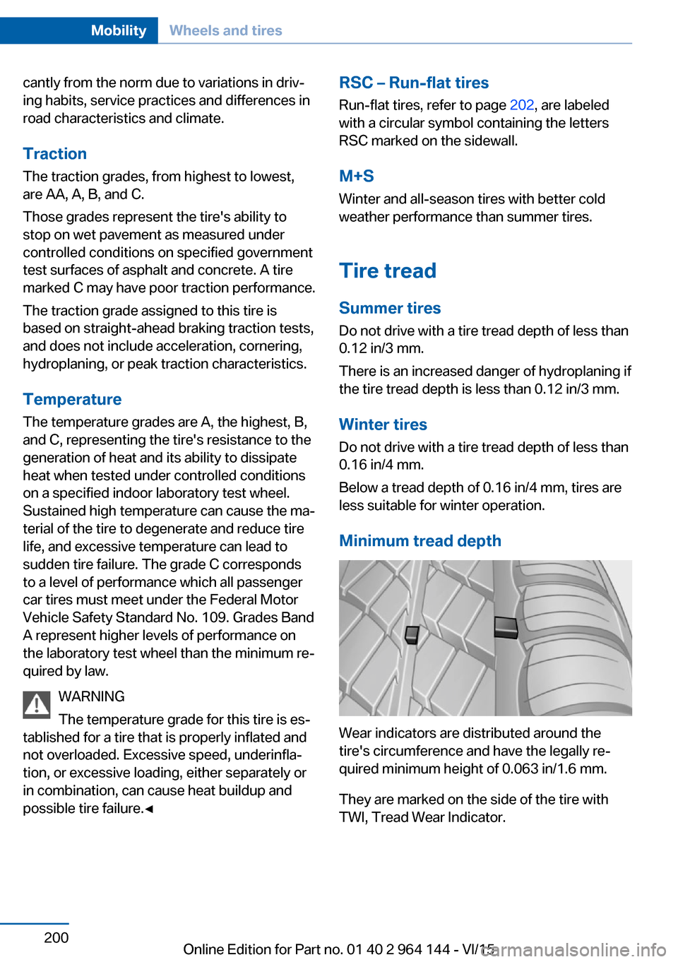
Minimum tread depth
Wear indicators are distributed around the
tire's circumference and have the legally re‐
quired minimum height of 0.063 in/1.6 mm.
They are marked on the side of the tire with
TWI, Tread Wear Indicator.
Seite 200MobilityWheels and tires200
Online Edition for Part no. 01 40 2 964 144 - VI/15
Page 220 of 253
3.Install the new bulb in reverse order of re‐
moval.4.Place the cover according to the arrow
markings on the headlight housing.5.Close the headlight housing with the lid.
Xenon headlights
Information
Because of the long service life of these bulbs,
the likelihood of failure is very low. Switching
the lights on and off frequently shortens their
service life.
If a bulb fails, turn on the front fog lights and
continue the trip with great care. Comply with
local regulations.
DANGER
There can be high voltage in the lighting
system. There is danger to life. The manufac‐
turer of your vehicle recommends that the
work on the lighting system including bulb re‐
placement be performed by a dealer’s service
center or another qualified service center or re‐
pair shop.◀
For checking and adjusting headlamp aim,
contact a dealer’s service center or another
qualified service center or repair shop.
Overview
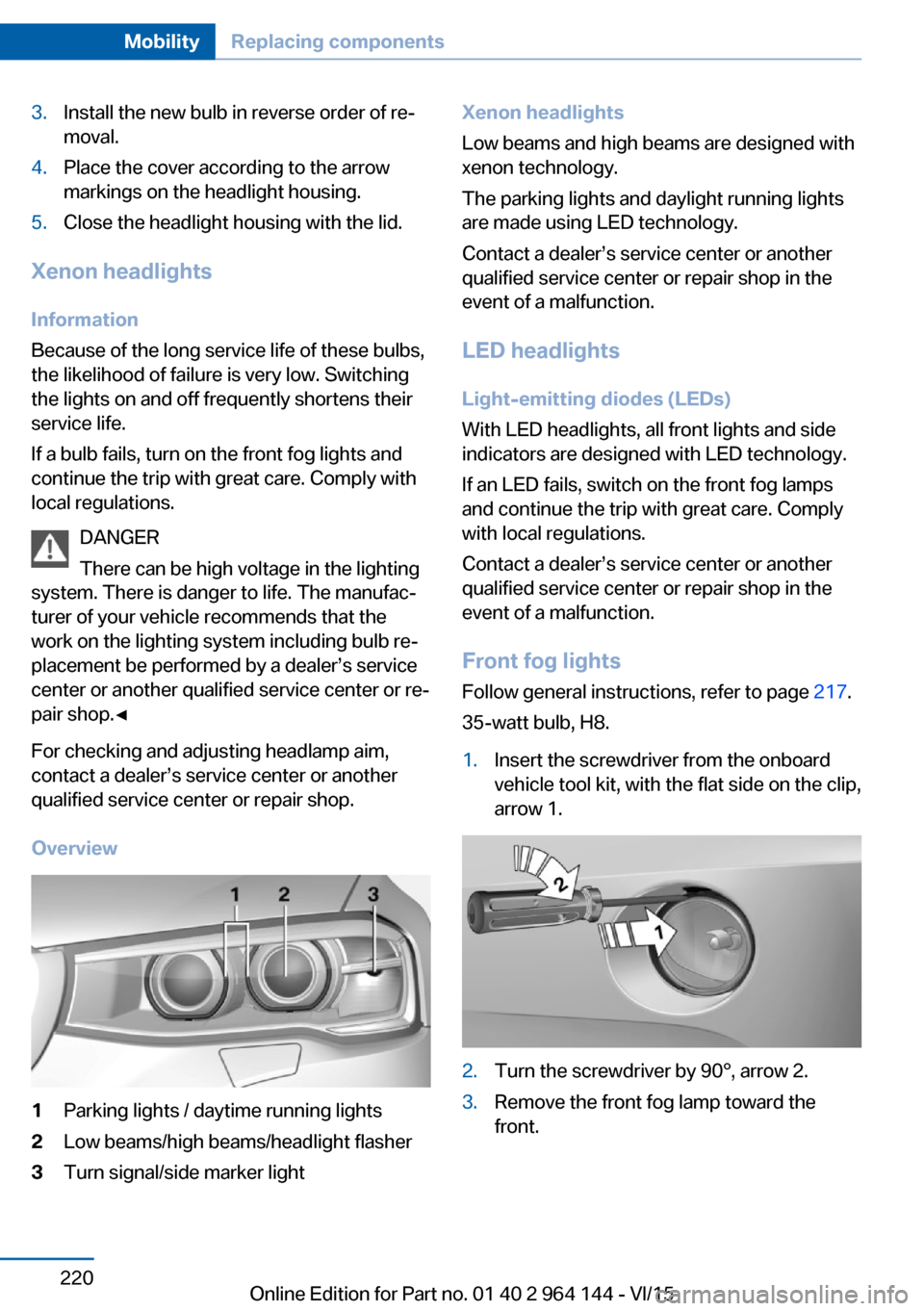
1Parking lights / daytime running lights2Low beams/high beams/headlight flasher3Turn signal/side marker lightXenon headlights
Low beams and high beams are designed with
xenon technology.
The parking lights and daylight running lights
are made using LED technology.
Contact a dealer’s service center or another
qualified service center or repair shop in the
event of a malfunction.
LED headlights Light-emitting diodes (LEDs)
With LED headlights, all front lights and side
indicators are designed with LED technology.
If an LED fails, switch on the front fog lamps
and continue the trip with great care. Comply with local regulations.
Contact a dealer’s service center or another
qualified service center or repair shop in the
event of a malfunction.
Front fog lights
Follow general instructions, refer to page 217.
35-watt bulb, H8.1.Insert the screwdriver from the onboard
vehicle tool kit, with the flat side on the clip,
arrow 1.2.Turn the screwdriver by 90°, arrow 2.3.Remove the front fog lamp toward the
front.Seite 220MobilityReplacing components220
Online Edition for Part no. 01 40 2 964 144 - VI/15
Page 246 of 253
Hood 207
Horn 14
Hot exhaust system 177
HUD Head-up Display 95
Hydroplaning 177
I Ice warning, see External temperature warning 87
Icy roads, see External tem‐ perature warning 87
Identification marks, tires 199
Identification number, see ve‐ hicle identification num‐
ber 10
iDrive 18
Ignition key, see Remote con‐ trol 34
Ignition off 67
Ignition on 67
Indication of a flat tire 107 , 110
Indicator and alarm lamps, see Check Control 83
Indicator lamp, see Check Control 83
Individual air distribu‐ tion 157, 160
Individual settings, see Per‐ sonal Profile 35
Inflation pressure, tires 196
Inflation pressure warning, tires 110
Info display, refer to On- Board computer 92
Information 6
Initialize, Tire Pressure Moni‐ tor TPM 107
Initializing, Flat Tire Monitor FTM 110
Instrument cluster 82
Instrument cluster, electronic displays 82
Instrument lighting 102
Integrated key 34 Integrated Owner's Manual in
the vehicle 30
Intelligent Emergency Re‐ quest 226
Intelligent Safety 112
Intensity, AUTO pro‐ gram 159
Interior equipment 163
Interior lights 102
Interior lights during unlock‐ ing 37
Interior lights with the vehicle locked 38
Interior motion sensor 47
Interior rearview mirror, auto‐ matic dimming feature 61
Interior rearview mirror, man‐ ually dimmable 61
Internet page 6
Interval display, service re‐ quirements 89
Interval mode 75
J
Jacking points for the vehicle jack 224
Joystick, Steptronic transmis‐ sion 78
Jump-starting 227
K
Key/remote control 34
Keyless Go, see Comfort Ac‐ cess 42
Key Memory, see Personal Profile 35
Kickdown, Steptronic trans‐ mission 77
Knee airbag 104
L Label on recommended tires 201 Lamp in the exterior mirror,
see Active Blind Spot De‐
tection 123
Lamp replacement 217
Lamp replacement, front 218
Lamp replacement, rear 221
Lane departure warning 121
Lane margin, warning 121
Language on Control Dis‐ play 95
Lashing eyes, securing cargo 181
LATCH child restraint sys‐ tem 65
Launch Control 80
Leather, care 232
LEDs, light-emitting di‐ odes 218
Letters and numbers, enter‐ ing 25
Light 98
Light alloy wheels, care 233
Light control 100
Light-emitting diodes, LEDs 218
Lighter 165
Lighting 98
Lights and bulbs 217
Light switch 98
Load 181
Loading 180
Lock, door 39
Locking/unlocking via door lock 39
Locking/unlocking with re‐ mote control 37
Locking, automatic 46
Locking, settings 45
Lock, power window 49
Locks, doors, and win‐ dows 66
Low beams 98
Low beams, automatic, see High-beam Assistant 100
Lower back support 54 Seite 246ReferenceEverything from A to Z246
Online Edition for Part no. 01 40 2 964 144 - VI/15