BMW X5 2000 E53 Central Body Electronics Service Manual
Manufacturer: BMW, Model Year: 2000, Model line: X5, Model: BMW X5 2000 E53Pages: 64, PDF Size: 4.03 MB
Page 41 of 64
ZKE - 41
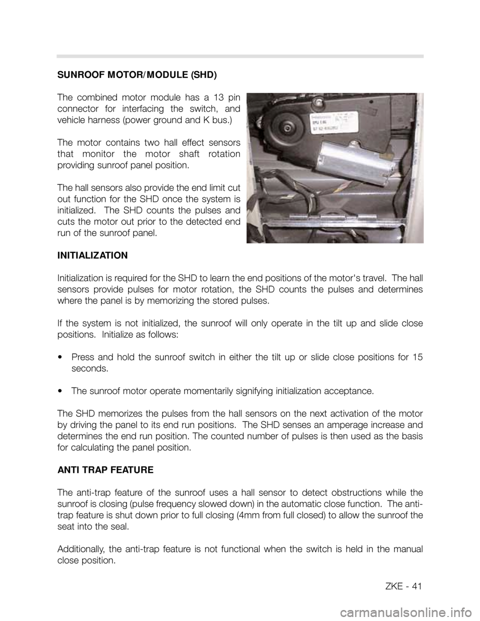
SUNROOF MOTOR/MODULE (SHD)
The combined motor module has a 13 pin
connector for interfacing the switch, and
vehicle harness (power ground and K bus.)
The motor contains two hall effect sensors
that monitor the motor shaft rotation
providing sunroof panel position.
The hall sensors also provide the end limit cut
out function for the SHD once the system is
initialized. The SHD counts the pulses and
cuts the motor out prior to the detected end
run of the sunroof panel.
INITIALIZATION
Initialization is required for the SHD to learn the end positions of the motor's travel. The hall
sensors provide pulses for motor rotation, the SHD counts the pulses and determines
where the panel is by memorizing the stored pulses.
If the system is not initialized, the sunroof will only operate in the tilt up and slide close
positions. Initialize as follows:
• Press and hold the sunroof switch in either the tilt up or slide close positions for 15
seconds.
• The sunroof motor operate momentarily signifying initialization acceptance.
The SHD memorizes the pulses from the hall sensors on the next activation of the motor
by driving the panel to its end run positions. The SHD senses an amperage increase and
determines the end run position. The counted number of pulses is then used as the basis
for calculating the panel position.
ANTI TRAP FEATURE
The anti-trap feature of the sunroof uses a hall sensor to detect obstructions while the
sunroof is closing (pulse frequency slowed down) in the automatic close function. The anti-
trap feature is shut down prior to full closing (4mm from full closed) to allow the sunroof the
seat into the seal.
Additionally, the anti-trap feature is not functional when the switch is held in the manual
close position.
Page 42 of 64
ZKE - 42
SHD SELF DIAGNOSIS
The SHD monitors its operation and stores fault codes if a defect is determined: The SHD
monitors the following conditions:
• SHD motor relays:The relays are checked for sticking contacts (plausibility) and non
functional contacts.
• Hall effect position sensors:The SHD must detect a pulse frequency from the hall
effect sensor(s) during operation.
• Sunroof Switch: The SHD monitors the signal plausibility of the coded signaling from
the sunroof switch.
SUNROOF FAULT RESPONSE CHARACTERISTICS
If a fault occurs with any of these functions, the SHD responds as follows:
• Overrides the end run detection.
• Switches the motor off if the relay contacts stick for more than 500 ms.
• Switches the motor off if pulses are not received.
EMERGENCY OPERATION OF SUNROOF
If the sunroof motor does not respond to the switch signals, the hex key in the trunk lid tool
kit is used to manually turn the motor shaft drive as on previous systems
Page 43 of 64
ZKE - 43
INTERIOR LIGHTING
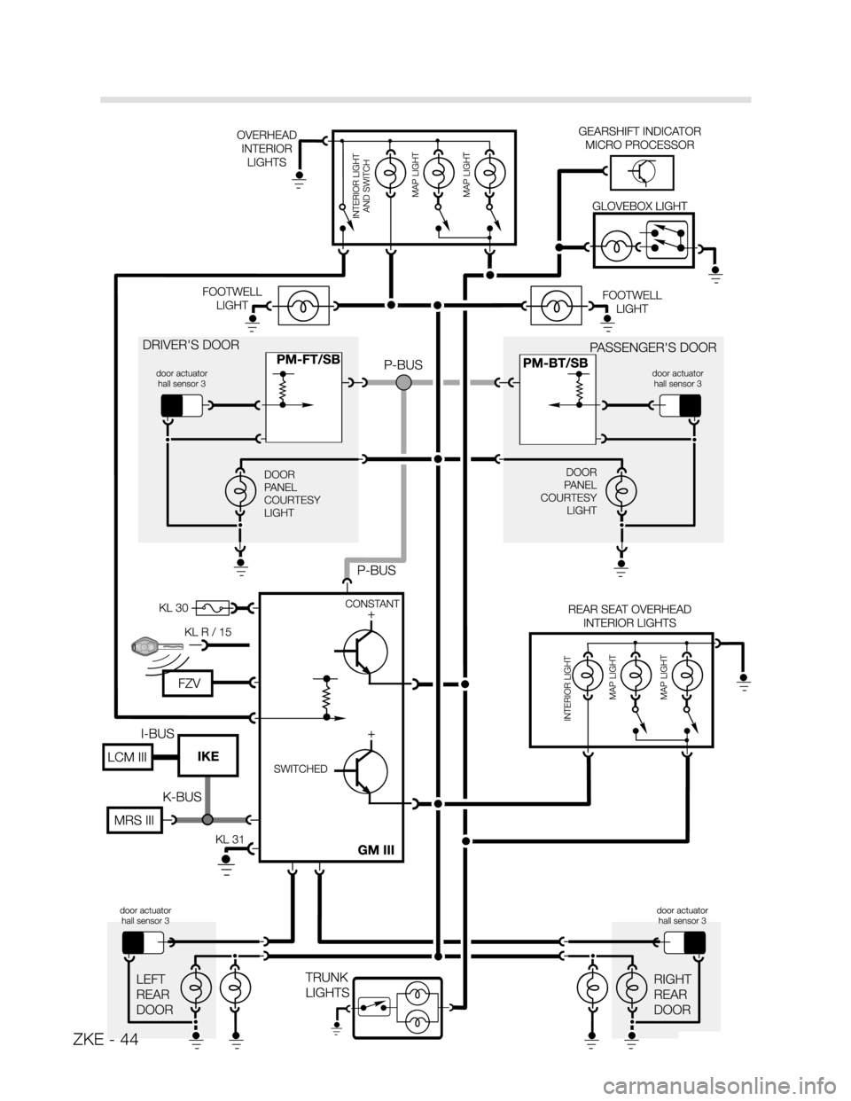
The GM controls the interior lighting automatically with the status change of several moni-
tored inputs. The lighting can also be manually controlled using the interior light switch.
COMPONENTS
DOOR CONTACTS: The door lock actuators contain a hall effect sensor for the purpose
of monitoring door open/closed status (hall sensor 3 in the driver's door actuator). The hall
effect sensor is located directly behind the rotary latch plate encased in the actuator. The
sensor is activated by the rotary latch plate's position. A change in current flow informs the
General module when a door is opened or closed.
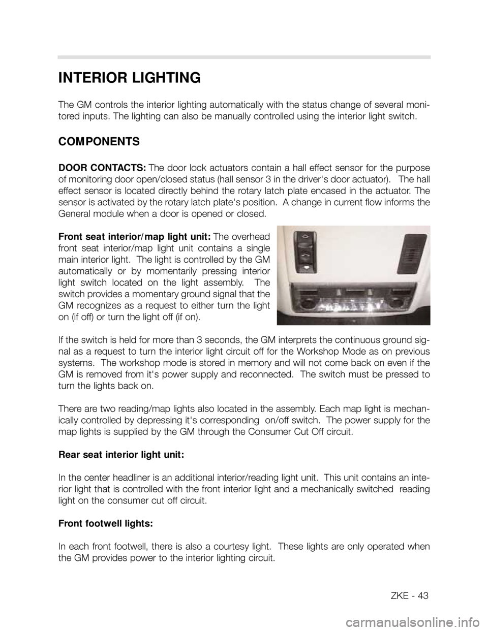
Front seat interior/map light unit: The overhead
front seat interior/map light unit contains a single
main interior light. The light is controlled by the GM
automatically or by momentarily pressing interior
light switch located on the light assembly. The
switch provides a momentary ground signal that the
GM recognizes as a request to either turn the light
on (if off) or turn the light off (if on).
If the switch is held for more than 3 seconds, the GM interprets the continuous ground sig-
nal as a request to turn the interior light circuit off for the Workshop Mode as on previous
systems. The workshop mode is stored in memory and will not come back on even if the
GM is removed from it's power supply and reconnected. The switch must be pressed to
turn the lights back on.
There are two reading/map lights also located in the assembly. Each map light is mechan-
ically controlled by depressing it's corresponding on/off switch. The power supply for the
map lights is supplied by the GM through the Consumer Cut Off circuit.
Rear seat interior light unit:
In the center headliner is an additional interior/reading light unit. This unit contains an inte-
rior light that is controlled with the front interior light and a mechanically switched reading
light on the consumer cut off circuit.
Front footwell lights:
In each front footwell, there is also a courtesy light. These lights are only operated when
the GM provides power to the interior lighting circuit.
Page 44 of 64
ZKE - 44
Page 45 of 64
ZKE - 45
AUTOMATIC CONTROL FUNCTION
The GM provides 12 volts (linear application providing soft on feature) to the interior light-
ing circuit when the one of the following input signal statuses change:
• Door contact hall sensor active (door opened)
• An Unlock request from the driver's door key lock hall sensors are received. This only
occurs if the ignition switch is off.
• An Unlock request is from the FZV keyless entry system is received via the K bus. This
only occurs if the ignition switch is off as well.
• The ignition switch is switched off and the vehicle exterior lights (LCM III) have been on
for a minimum of 2 minutes prior. This information is provided to the GM via the K bus.
• Active crash signal from the MRS III control module.
• Lock button of FZV key is pressed with the vehicle is already locked (interior search
function).
The GM gradually reduces the full 12 volt power supply (linear reduction providing soft off)
until the lights are off when the following input signal statuses change:
• Immediately after the ignition switch is turned to KL R with the driver's door hall sensor
door contact closed.
• When the vehicle is locked (single or double) with the door contacts closed.
• When the vehicle door contacts are closed. The lights remain on for 20 seconds and
then go to soft off.
• After the interior search function is activated, the lights will automatically turn off (soft off)
after 8 seconds.
• After 16 minutes with a door contact active (open door) and the key off, the lights are
switched off (consumer cutoff function).
• The component activation function of the DIS also has the ability to switch the lights.
The Interior lighting output circuit of the GM is approximately 3.5 amps with all lights on.
Page 46 of 64
ZKE - 46
ANTI-THEFT (DWA) SYSTEM
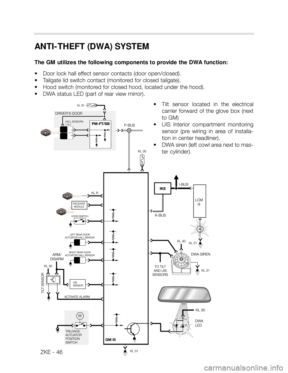
The GM utilizes the following components to provide the DWA function:
• Door lock hall effect sensor contacts (door open/closed).
• Tailgate lid switch contact (monitored for closed tailgate).
• Hood switch (monitored for closed hood, located under the hood).
• DWA status LED (part of rear view mirror).
• Tilt sensor located in the electrical
carrier forward of the glove box (next
to GM)
• UIS Interior compartment monitoring
sensor (pre wiring in area of installa-
tion in center headliner).
• DWA siren (left cowl area next to mas-
ter cylinder).
Page 47 of 64
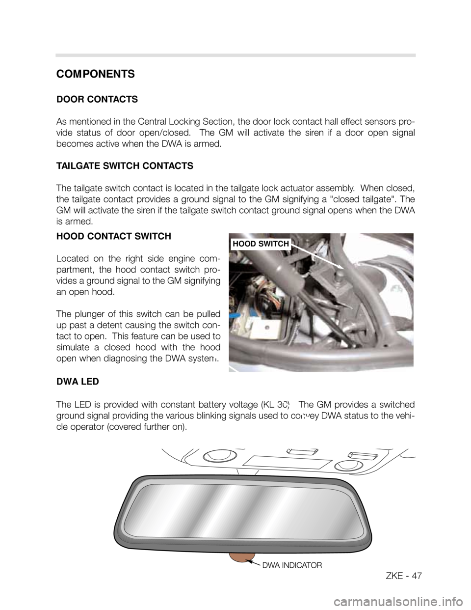
HOOD CONTACT SWITCH
Located on the right side engine com-
partment, the hood contact switch pro-
vides a ground signal to the GM signifying
an open hood.
The plunger of this switch can be pulled
up past a detent causing the switch con-
tact to open. This feature can be used to
simulate a closed hood with the hood
open when diagnosing the DWA system.
DWA LED
The LED is provided with constant battery voltage (KL 30). The GM provides a switched
ground signal providing the various blinking signals used to convey DWA status to the vehi-
cle operator (covered further on).HOOD SWITCH
COMPONENTS
DOOR CONTACTS
As mentioned in the Central Locking Section, the door lock contact hall effect sensors pro-
vide status of door open/closed. The GM will activate the siren if a door open signal
becomes active when the DWA is armed.
TAILGATE SWITCH CONTACTS
The tailgate switch contact is located in the tailgate lock actuator assembly. When closed,
the tailgate contact provides a ground signal to the GM signifying a "closed tailgate". The
GM will activate the siren if the tailgate switch contact ground signal opens when the DWA
is armed.
ZKE - 47
Page 48 of 64
ZKE - 48
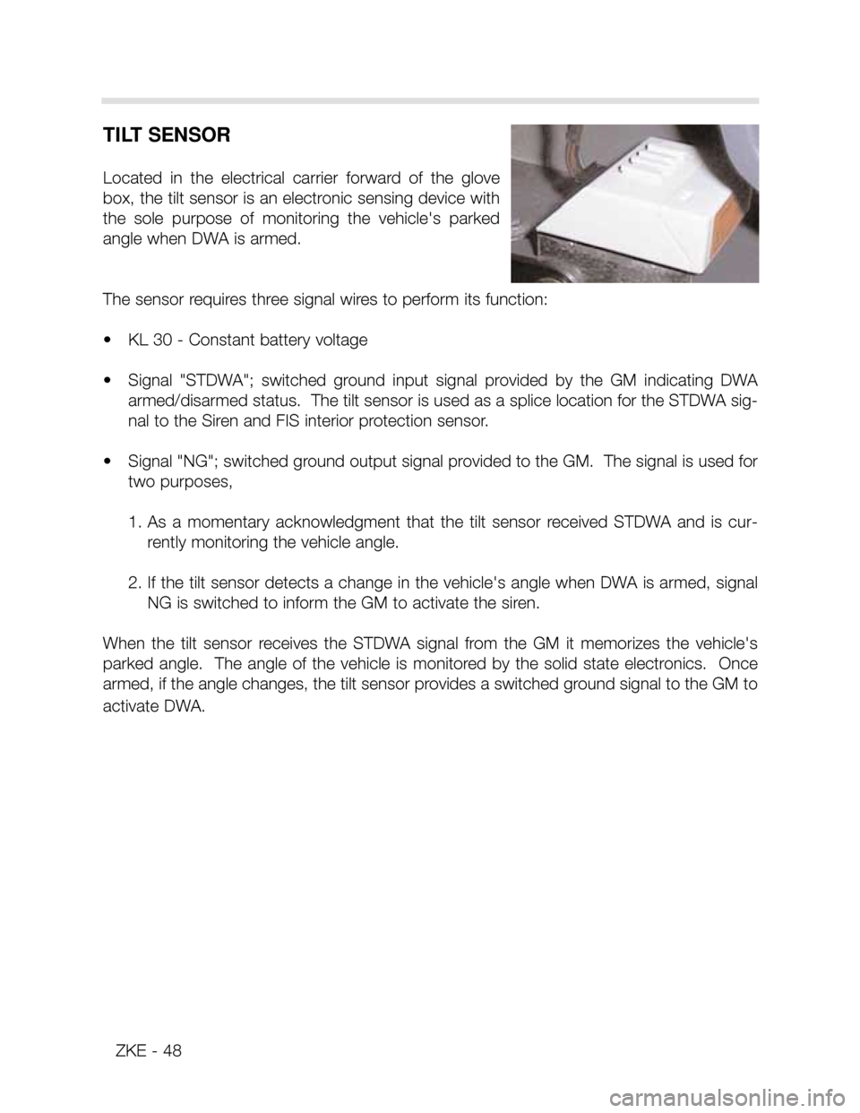
TILT SENSOR
Located in the electrical carrier forward of the glove
box, the tilt sensor is an electronic sensing device with
the sole purpose of monitoring the vehicle's parked
angle when DWA is armed.
The sensor requires three signal wires to perform its function:
• KL 30 - Constant battery voltage
• Signal "STDWA"; switched ground input signal provided by the GM indicating DWA
armed/disarmed status. The tilt sensor is used as a splice location for the STDWA sig-
nal to the Siren and FIS interior protection sensor.
• Signal "NG"; switched ground output signal provided to the GM. The signal is used for
two purposes,
1. As a momentary acknowledgment that the tilt sensor received STDWA and is cur-
rently monitoring the vehicle angle.
2. If the tilt sensor detects a change in the vehicle's angle when DWA is armed, signal
NG is switched to inform the GM to activate the siren.
When the tilt sensor receives the STDWA signal from the GM it memorizes the vehicle's
parked angle. The angle of the vehicle is monitored by the solid state electronics. Once
armed, if the angle changes, the tilt sensor provides a switched ground signal to the GM to
activate DWA.
Page 49 of 64
ZKE - 49
INTERIOR PROTECTION (UIS)
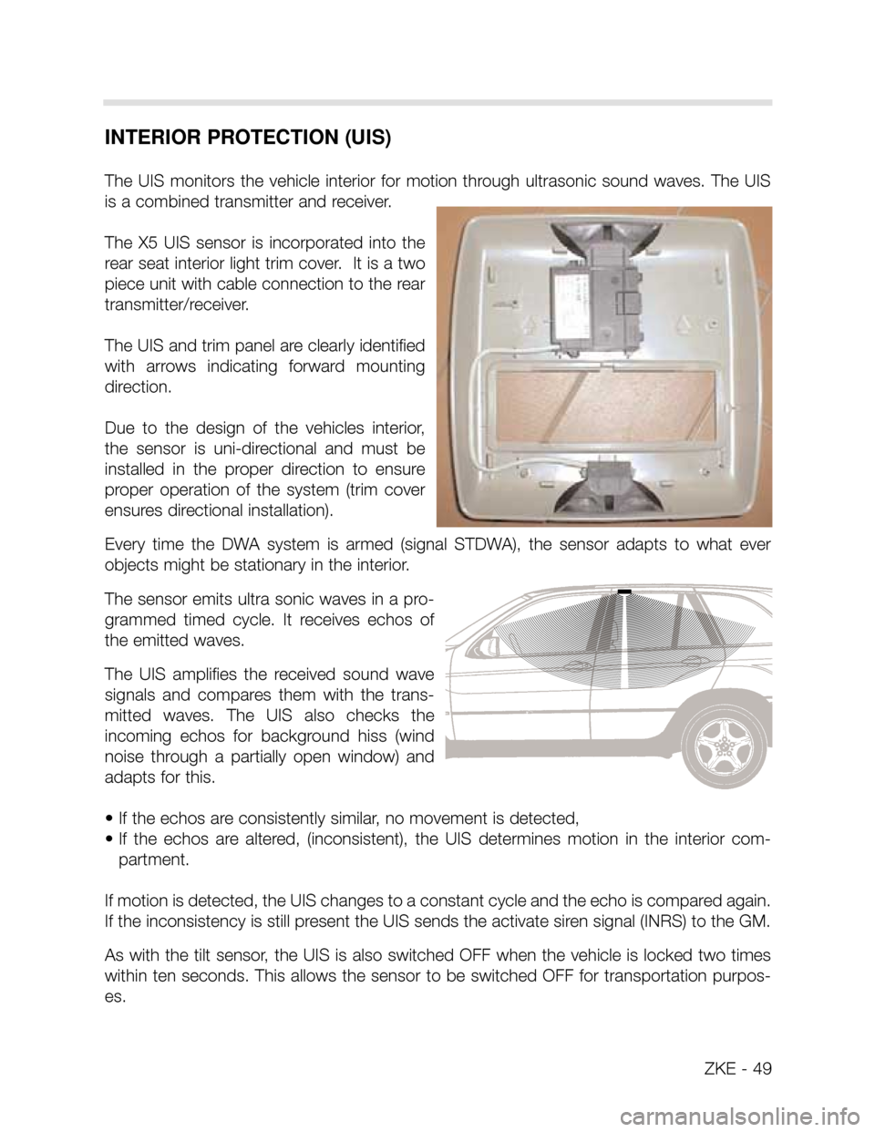
The UIS monitors the vehicle interior for motion through ultrasonic sound waves. The UIS
is a combined transmitter and receiver.
The X5 UIS sensor is incorporated into the
rear seat interior light trim cover. It is a two
piece unit with cable connection to the rear
transmitter/receiver.
The UIS and trim panel are clearly identified
with arrows indicating forward mounting
direction.
Due to the design of the vehicles interior,
the sensor is uni-directional and must be
installed in the proper direction to ensure
proper operation of the system (trim cover
ensures directional installation).
Every time the DWA system is armed (signal STDWA), the sensor adapts to what ever
objects might be stationary in the interior.
The sensor emits ultra sonic waves in a pro-
grammed timed cycle. It receives echos of
the emitted waves.
The UIS amplifies the received sound wave
signals and compares them with the trans-
mitted waves. The UIS also checks the
incoming echos for background hiss (wind
noise through a partially open window) and
adapts for this.
• If the echos are consistently similar, no movement is detected,
• If the echos are altered, (inconsistent), the UIS determines motion in the interior com-
partment.
If motion is detected, the UIS changes to a constant cycle and the echo is compared again.
If the inconsistency is still present the UIS sends the activate siren signal (INRS) to the GM.
As with the tilt sensor, the UIS is also switched OFF when the vehicle is locked two times
within ten seconds. This allows the sensor to be switched OFF for transportation purpos-
es.
Page 50 of 64
ALARM SIREN
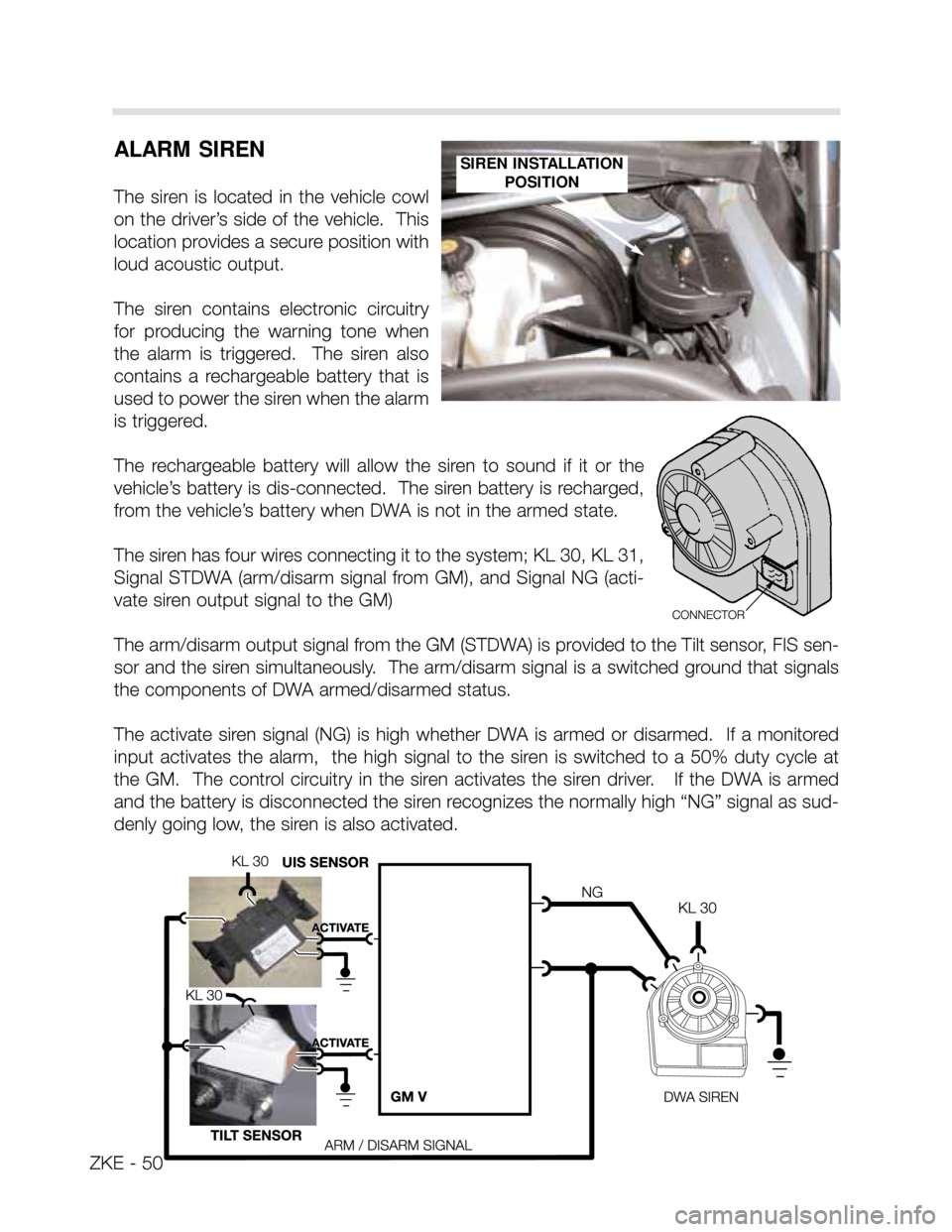
The siren is located in the vehicle cowl
on the driver’s side of the vehicle. This
location provides a secure position with
loud acoustic output.
The siren contains electronic circuitry
for producing the warning tone when
the alarm is triggered. The siren also
contains a rechargeable battery that is
used to power the siren when the alarm
is triggered.
The rechargeable battery will allow the siren to sound if it or the
vehicle’s battery is dis-connected. The siren battery is recharged,
from the vehicle’s battery when DWA is not in the armed state.
The siren has four wires connecting it to the system; KL 30, KL 31,
Signal STDWA (arm/disarm signal from GM), and Signal NG (acti-
vate siren output signal to the GM)
The arm/disarm output signal from the GM (STDWA) is provided to the Tilt sensor, FIS sen-
sor and the siren simultaneously. The arm/disarm signal is a switched ground that signals
the components of DWA armed/disarmed status.
The activate siren signal (NG) is high whether DWA is armed or disarmed. If a monitored
input activates the alarm, the high signal to the siren is switched to a 50% duty cycle at
the GM. The control circuitry in the siren activates the siren driver. If the DWA is armed
and the battery is disconnected the siren recognizes the normally high “NG” signal as sud-
denly going low, the siren is also activated.
SIREN INSTALLATION
POSITION
ZKE - 50