air BMW X5 2000 E53 Level Control System Manual
[x] Cancel search | Manufacturer: BMW, Model Year: 2000, Model line: X5, Model: BMW X5 2000 E53Pages: 57, PDF Size: 1.89 MB
Page 27 of 57
27
Level Control Systems
Two Axle Air Suspension (E53 EHC II)
Purpose of the System
The two axle air suspension system (EHC2) offers advantages over the single-axle air sus-
pension with respect to ride comfort and off-road capability.
Lowering the entire body makes it easier to enter, exit, load and unload the vehicle.
The vehicle's off-road capability was improved by providing the possibility for increasing the
ground clearance of the body.
The driver can now choose between three different ride levels which can be set with a rock-
er switch, as required. Automatic ride-height control for payload compensation and
automatic inclination compensation continue to be fitted.
D De
ef
fi
ic
ci
it
ts
s
o
of
f
t
th
he
e
o
ol
ld
d
s
sy
ys
st
te
em
m
The automatic payload compensation facility for the single-axle air suspension did not per-
mit driver control. The driver could not actively control the system to make it easier to enter
and exit or load the vehicle.
Ride level was compensated via the rear axle only.
A Ad
dv
va
an
nt
ta
ag
ge
es
s
o
of
f
t
th
he
e
n
ne
ew
w
s
sy
ys
st
te
em
m
The new system allows the ride-height control system to be controlled actively by the dri-
ver.
The twin axle air suspension allows both axles to be lowered evenly and in parallel.
As a result, it is easier for the occupants to enter, exit, load and unload the vehicle.
On the E39, the load of the complete rear axle was born for the first time by air suspension
in combination with the optional ride height control system. The system was controlled
automatically under all operation conditions, and there was no possibility for driver inter-
vention on the X5, the rear axle previously had single axle air suspension only. The air sup-
ply unit and the control unit were adopted from the E39. The air springs were adapted to
the X5.
There is a standard version and a sports version.
The ride-height control system (EHC) was supplied as standard in combination with the
M62 engine and is available as an optional extra in combination with the M54 engine.
EHC2 is optional on both the M62 and M54 versions of the X5 and not available on the
4.6is X5.
Page 28 of 57
28
Level Control Systems
System components
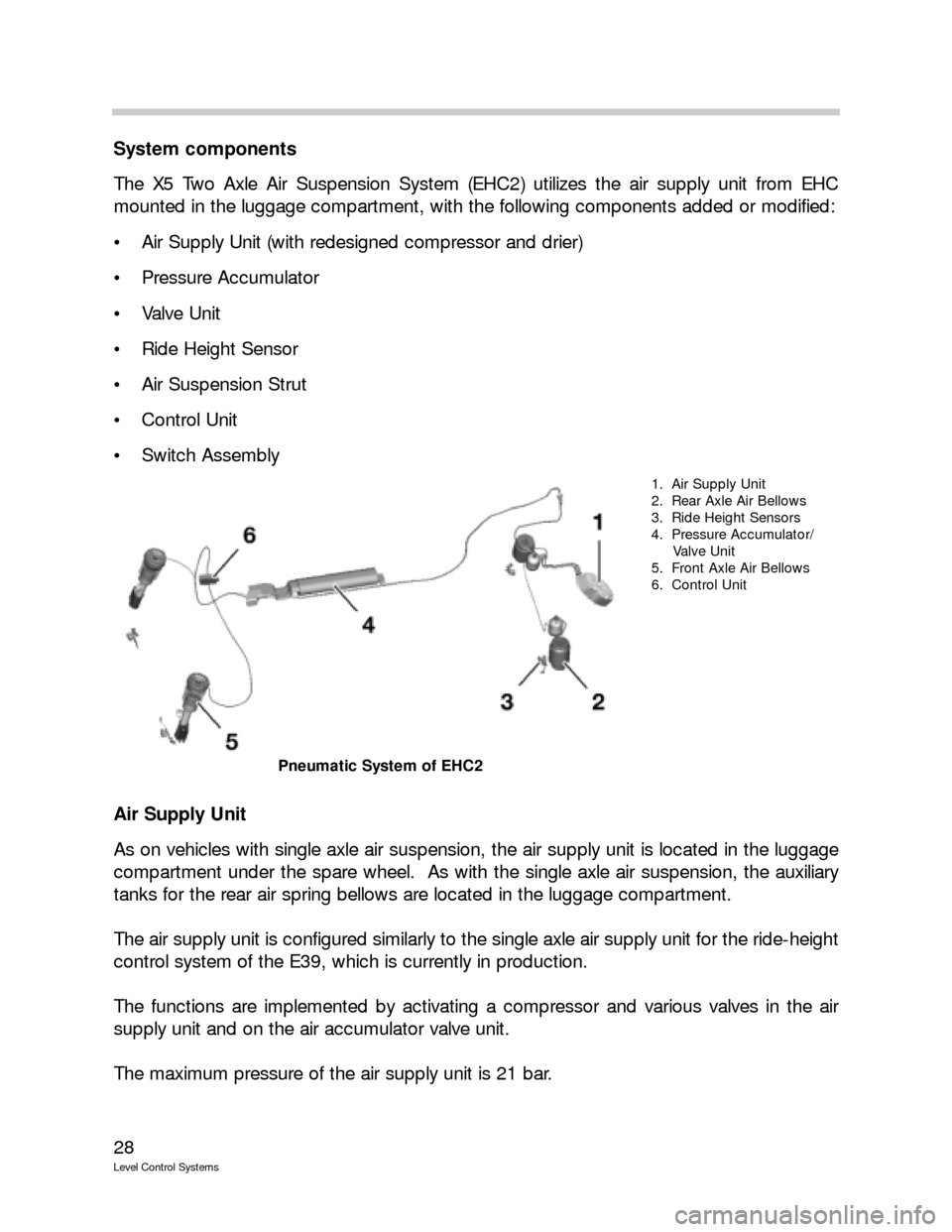
The X5 Two Axle Air Suspension System (EHC2) utilizes the air supply unit from EHC
mounted in the luggage compartment, with the following components added or modified:
Air Supply Unit (with redesigned compressor and drier)
Pressure Accumulator
Valve Unit
Ride Height Sensor
Air Suspension Strut
Control Unit
Switch Assembly
Air Supply Unit
As on vehicles with single axle air suspension, the air supply unit is located in the luggage
compartment under the spare wheel. As with the single axle air suspension, the auxiliary
tanks for the rear air spring bellows are located in the luggage compartment.
The air supply unit is configured similarly to the single axle air supply unit for the ride-height
control system of the E39, which is currently in production.
The functions are implemented by activating a compressor and various valves in the air
supply unit and on the air accumulator valve unit.
The maximum pressure of the air supply unit is 21 bar.
1. Air Supply Unit
2. Rear Axle Air Bellows
3. Ride Height Sensors
4. Pressure Accumulator/
Valve Unit
5. Front Axle Air Bellows
6. Control Unit
Pneumatic System of EHC2
Page 29 of 57
29
Level Control Systems
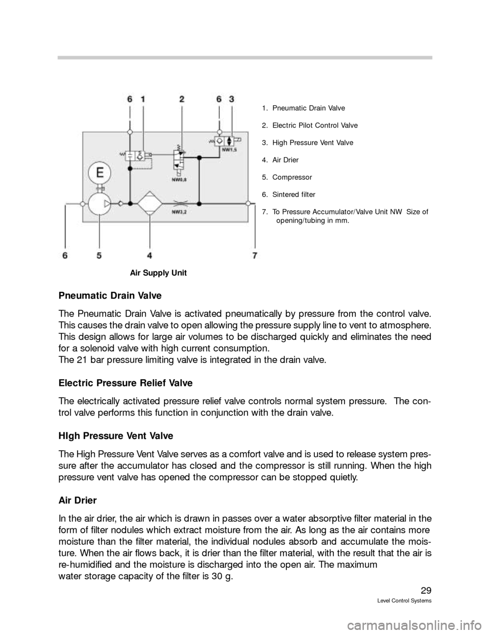
Pneumatic Drain Valve
The Pneumatic Drain Valve is activated pneumatically by pressure from the control valve.
This causes the drain valve to open allowing the pressure supply line to vent to atmosphere.
This design allows for large air volumes to be discharged quickly and eliminates the need
for a solenoid valve with high current consumption.
The 21 bar pressure limiting valve is integrated in the drain valve.
Electric Pressure Relief Valve
The electrically activated pressure relief valve controls normal system pressure. The con-
trol valve performs this function in conjunction with the drain valve.
HIgh Pressure Vent Valve
The High Pressure Vent Valve serves as a comfort valve and is used to release system pres-
sure after the accumulator has closed and the compressor is still running. When the high
pressure vent valve has opened the compressor can be stopped quietly.
Air Drier
In the air drier, the air which is drawn in passes over a water absorptive filter material in the
form of filter nodules which extract moisture from the air. As long as the air contains more
moisture than the filter material, the individual nodules absorb and accumulate the mois-
ture. When the air flows back, it is drier than the filter material, with the result that the air is
re-humidified and the moisture is discharged into the open air. The maximum
water storage capacity of the filter is 30 g.
1. Pneumatic Drain Valve
2. Electric Pilot Control Valve
3. High Pressure Vent Valve
4. Air Drier
5. Compressor
6. Sintered filter
7. To Pressure Accumulator/Valve Unit NW Size of
opening/tubing in mm.
Air Supply Unit
Page 30 of 57
30
Level Control Systems
Compressor
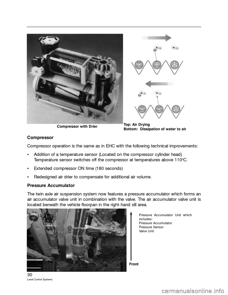
Compressor operation is the same as in EHC with the following technical improvements:
Addition of a temperature sensor (Located on the compressor cylinder head)
Temperature sensor switches off the compressor at temperatures above 110
0C.
Extended compressor ON time (180 seconds)
Redesigned air drier to compensate for additional air volume.
Pressure Accumulator
The twin axle air suspension system now features a pressure accumulator which forms an
air accumulator valve unit in combination with the valve. The air accumulator valve unit is
located beneath the vehicle floorpan in the right-hand sill area.
Top: Air Drying
Bottom: Dissipation of water to airCompressor with Drier
Pressure Accumulator Unit which
includes:
Pressure Accumulator
Pressure Sensor
Valve Unit
Front
Page 31 of 57
31
Level Control Systems
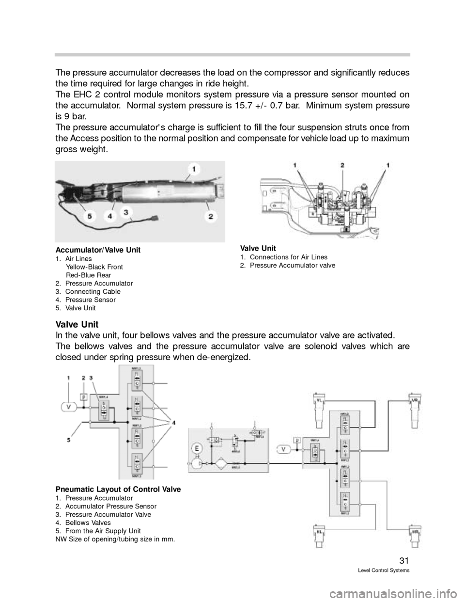
The pressure accumulator decreases the load on the compressor and significantly reduces
the time required for large changes in ride height.
The EHC 2 control module monitors system pressure via a pressure sensor mounted on
the accumulator. Normal system pressure is 15.7 +/- 0.7 bar. Minimum system pressure
is 9 bar.
The pressure accumulator's charge is sufficient to fill the four suspension struts once from
the Access position to the normal position and compensate for vehicle load up to maximum
gross weight.
Valve Unit
In the valve unit, four bellows valves and the pressure accumulator valve are activated.
The bellows valves and the pressure accumulator valve are solenoid valves which are
closed under spring pressure when de-energized.
Accumulator/Valve Unit
1. Air Lines
Yellow-Black Front
Red-Blue Rear
2. Pressure Accumulator
3. Connecting Cable
4. Pressure Sensor
5. Valve Unit
Valve Unit
1. Connections for Air Lines
2. Pressure Accumulator valve
Pneumatic Layout of Control Valve
1. Pressure Accumulator
2. Accumulator Pressure Sensor
3. Pressure Accumulator Valve
4. Bellows Valves
5. From the Air Supply Unit
NW Size of opening/tubing size in mm.
Page 33 of 57
33
Level Control Systems
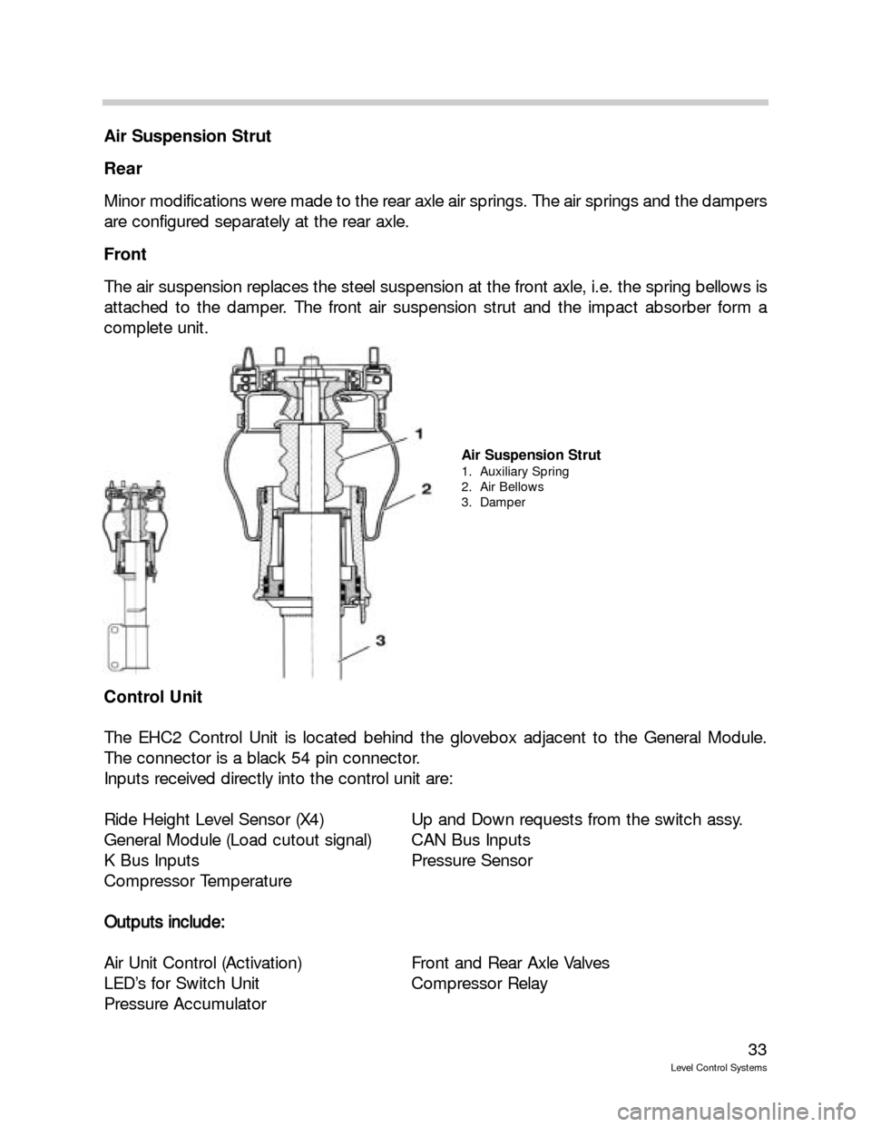
Air Suspension Strut
Rear
Minor modifications were made to the rear axle air springs. The air springs and the dampers
are configured separately at the rear axle.
Front
The air suspension replaces the steel suspension at the front axle, i.e. the spring bellows is
attached to the damper. The front air suspension strut and the impact absorber form a
complete unit.
Control Unit
The EHC2 Control Unit is located behind the glovebox adjacent to the General Module.
The connector is a black 54 pin connector.
Inputs received directly into the control unit are:
Ride Height Level Sensor (X4) Up and Down requests from the switch assy.
General Module (Load cutout signal) CAN Bus Inputs
K Bus Inputs Pressure Sensor
Compressor Temperature
O Ou
ut
tp
pu
ut
ts
s
i
in
nc
cl
lu
ud
de
e:
:
Air Unit Control (Activation) Front and Rear Axle Valves
LED’s for Switch Unit Compressor Relay
Pressure Accumulator
Air Suspension Strut
1. Auxiliary Spring
2. Air Bellows
3. Damper
Page 35 of 57
35
Level Control Systems
Principle of Operation
Ride Height Control Operations
In addition to the automatic ride-height control system for payload compensation, the dri-
ver can set three different vehicle ride heights.
Off-road (+25 mm), high ground clearance to a max. speed of 50 km/h
Standard (0 mm), normal ride level
Access (-35 mm), for entry and exit, loading and unloading to a max. speed of 35 km/h
or can be activated in Standard mode at road speeds < 25 km/h
The various heights are selected by scroll rocker. Light emitting diodes indicate the present
ride height setting.
Ride height can be adjusted from terminal 15 and with the doors closed. The hood and tail-
gate may be open.
The system also controls inclination automatically, like the single axle air suspension.
All control operations are executed without stopping at intermediate levels. The vehicle is
configured pneumatically in such a way that the front and rear axles can be lowered in par-
allel in any load situation. Depending on the load situation, either the front axle or the rear
axle is slightly quicker. On account of the different control speeds, a difference in height
between the two axles is possible during all control operations. If a max. permissible thresh-
old is exceeded, the quicker axle is stopped briefly.
The various levels can be preselected while travelling. Changeover between ride levels is
effected at the speed threshold values defined in the control unit. The control unit monitors
the change-over.
As soon as the driver sets a new target ride level by pressing a button or when a change-
over is initiated automatically by a specific driving condition, the LED for the current ride
level remains lit and the LED for the target ride level begins to flash.
When the new level is reached, the LED for the previous level goes out and the LED for the
new level reached stays lit permanently.
Page 37 of 57
37
Level Control Systems
In addition to the LED indicator, the following text messages can
be displayed in the instrument cluster:
T TR
RA
AI
IL
LE
ER
R
M
MO
OD
DE
E
A coupled trailer is identified via the trailer connector. To avoid damaging the trailer and
the vehicle, changes of vehicle level are generally avoided. The standard level is "frozen."
If the trailer is coupled at a level other than the Standard level, the vehicle ride level is
not changed to Standard unless a button is pressed or the speed threshold for auto-
matic change-over is reached. The standard level is then "frozen" until the trailer con-
nector is disconnected.
R RI
ID
DE
E
H
HE
EI
IG
GH
HT
T
C
CO
ON
NT
TR
RO
OL
L
I
IN
NA
AC
CT
TI
IV
VE
E
Faults in the system and on the control unit which are only identified by the instrument
cluster, e.g. control unit disconnected
R RI
ID
DE
E
H
HE
EI
IG
GH
HT
T
C
CO
ON
NT
TR
RO
OL
L
I
IN
NA
AC
CT
TI
IV
VE
E
+
+
M
MA
AX
X.
.
6
60
0
k
km
m/
/h
h
For safety-critical faults (vehicle is too high or at inclination)
Control Modes
Sleep mode
If the vehicle is parked, it enters Sleep mode after 16 minutes. No further control opera-
tions are executed. A "watch dog" wakes up the control unit for a few minutes every 6
hours (wakeup mode) in order to compensate for possible inclination of the vehicle. (Vehicle
height may only be corrected once as air supply unit only operates with engine running.)
Wake-up
In wake-up mode, the control unit is woken up for a set period of time in order to com-
pensate for possible inclination of the vehicle. Inclination of the vehicle can be caused by
large temperature differences or by minor leaks. Adjustments to the front and rear axles
ensure that the vehicle is visually level. To minimize power consumption, the vehicle is low-
ered only. The nominal level of the lowest wheel serves as the nominal level for all other
wheels. The lowest nominal level to which the vehicle is lowered is the Access level (-35
mm).
Exception:if the vehicle is parked at Access level, the vehicle is lowered to max. -50 mm
in wake-up mode. If the vehicle is parked for a prolonged period of time and there is a leak
in the system, further loss of pressure does not produce a change of ride level since the
weight of the body is born by the auxiliary suspension and the residual tire pressure.
Advance /Overrun
When the vehicle is woken out of sleep mode by the load-cutout signal (VA), it normally
enters advance / overrun mode. Since the engine is not (no longer) running in this mode,
however, there are restrictions on the control operations that can be performed in order to
conserve the battery. Ride level compensation is restricted to tolerance ranges of 20 mm
and 25 mm in the up and down directions respectively. This serves to reduce the frequen-
cy of control operations.
Page 39 of 57
39
Level Control Systems
Workshop Hints
If a threshold level is exceeded on all 4 wheels when the vehicle is stationary, the control
unit assumes that the vehicle has been raised on a workshop platform.
There are three possible reset conditions for workshop platform recognition:
The original level values are undershot at all four wheels,
A selection is made by button,
A speed of >40 km/h is recognized for 3 s.
Vehicle jack
If the lowering speed at a wheel is too low during the lowering operation, the system
assumes that the wheel is jacked up. However, the downward velocity must be less than
a certain preprogrammed speed threshold. If the system detects a jacked wheel, it stores
the height of this wheel.
Car jack recognition is reset when the stored ride height is again undershot. When a trav-
elling speed of 40 km/h is maintained for at least 3 s, another control attempt is performed.
The car jack recognition can also be reset by button selection.
Please note that the system also controls ride height in diagnostic mode. For this reason,
Belt Mode must be activated before carrying out work on the system or before setting the
vehicle ride height.
Belt Mode:
Heights are fixed and are not compensated. If Belt Mode is set, the function LED is off. The
text message "ride-height control system inactive" appears in the instrument cluster.
Transport Mode:
The Transport Mode setting is for transportation purposes. When the ignition is turned on,
the message "ride-height control system inactive" appears. Heights are increased or
decreased depending on ignition key status, e.g. ride height is reduced when the vehicle is
lashed to a ship or train and raised when the "Engine on" signal is generated and when the
vehicle is transported on a transporter truck.
The correct ride height is set to ± 5 mm via "Activate components." The left and right ride
levels are set separately at the rear axle. The ride levels are then set at the front axle. The
left and right air springs are adjusted jointly for this purpose.
Following this, the new ride height for the front and rear axles is stored via the "Offset func-
tion."
Before replacing components, the system must be depressurized! This is done in the diag-
nostics via "control unit functions," "Component activation," "Pressure-relieve front axle/rear
axle." Repeat the activation procedure 6 times.
Page 40 of 57
40
Level Control Systems
If the fabric of the bellows is visible, then the bellows must be replaced.
Upon completion of repair work, the air suspension system of the vehicle raised on the
workshop platform must be refilled with air via the diagnostics. The activation procedures
must also be repeated 6 times. This prevents the bellows from being folded incorrectly.
The vehicle must with be set down on its wheels when the suspension struts are depres-
surized!
Important Workshop Hint
S Si
im
mi
il
la
ar
rl
ly
y,
,
a
a
d
de
ef
fe
ec
ct
ti
iv
ve
e
v
ve
eh
hi
ic
cl
le
e
w
wi
it
th
h
l
le
ea
ak
ky
y
p
pn
ne
eu
um
ma
at
ti
ic
c
s
sy
ys
st
te
em
m
m
mu
us
st
t
n
no
ot
t
b
be
e
r
ra
ai
is
se
ed
d
o
on
n
t
th
he
e
w
wo
or
rk
k-
-
s sh
ho
op
p
p
pl
la
at
tf
fo
or
rm
m.
.
I
If
f
d
de
ep
pr
re
es
ss
su
ur
ri
iz
ze
ed
d,
,
t
th
he
e
b
be
el
ll
lo
ow
ws
s
w
wo
ou
ul
ld
d
c
co
on
nt
tr
ra
ac
ct
t
u
un
nd
de
er
r
s
su
uc
ct
ti
io
on
n
f
fo
or
rm
mi
in
ng
g
i
in
nc
co
or
rr
re
ec
ct
t
f fo
ol
ld
ds
s.
.
T
Th
he
es
se
e
f
fo
ol
ld
ds
s
c
co
ou
ul
ld
d
r
re
es
su
ul
lt
t
i
in
n
m
ma
al
lf
fu
un
nc
ct
ti
io
on
ns
s
l
la
at
te
er
r
o
on
n.
.
Areas on the air bellows which can possibly become leaky are the O-ring at the piston rod
and the seal carrier on the roll piston.
The connectors attached to all cables are identical to the connections on the single-axle air
suspension. 6 mm cable is used. The tightening torque is 3+
1 Nm throughout the system.
Special care must be taken when handling breakage-prone plastic parts of air suspension
elements.
Upon completion of repair work, Belt mode must be deactivated via the diagnostics. The
function LED on the button comes on. No text message appears in the instrument cluster.
The system is OK and ready for operation.